![]() Service Literature
Service Literature
UNIT INFORMATION
EL18XCV
Corp. 100011 April 1, 2021
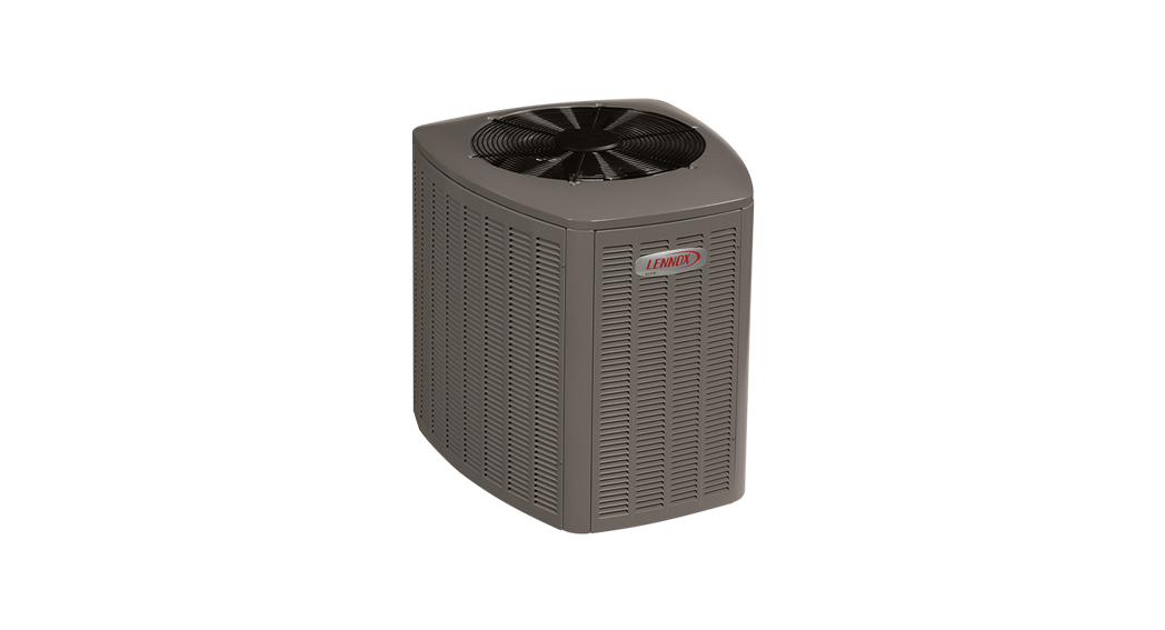
EL18XCV (HFC-410A) SERIES OUTDOOR UNITS
![]() WARNING
WARNING
Improper installation, adjustment, alteration, service, or maintenance can cause property damage, personal injury or loss of life. Installation and service must be performed by a licensed professional HVAC installer or equivalent, service agency, or gas supplier.![]() IMPORTANT
IMPORTANT
The Clean Air Act of 1990 bans the intentional venting of refrigerants (CFCs, HCFCs, and HFCs) as of July 1, 1992. Approved methods of recovery, recycling or reclaiming must be followed. Fines and/or incarceration may be levied for noncompliance.![]() IMPORTANT
IMPORTANT
This unit must be matched with an indoor coil as specified in Lennox Product Specification bulletin. Coils previously charged with HCFC-22 must be flushed.![]() CAUTION
CAUTION
As with any mechanical equipment, contact with sharp sheet metal edges can result in personal injury. Take care while handling this equipment and wear gloves and protective clothing.![]() WARNING
WARNING![]() Electric Shock Hazard. Can cause injury or death. The unit must be properly grounded in accordance with national and local codes. Line voltage is present at all components when the unit is not in operation on units with single pole contactors.
Electric Shock Hazard. Can cause injury or death. The unit must be properly grounded in accordance with national and local codes. Line voltage is present at all components when the unit is not in operation on units with single pole contactors.
Disconnect all remote electric power supplies before opening the access panel.
The unit may have multiple power supplies.
General Information
These instructions are intended as a general guide and do not supersede national or local codes in any way. Consult authorities having jurisdiction before installation.
The EL18XCV is a high-efficiency split system air conditioner with an all-aluminum coil, designed for use with HFC-410A refrigerant only.
The EL18XCVS024, S036, S048, S060, EL18XCV-024, -036, and -048 feature a variable capacity rotary compressor.
The EL18XCV-060 model features a variable-capacity scroll compressor. This unit must be installed with an approved indoor air handler or coil. See the Lennox EL18XCV Product Specifications bulletin (EHB) for approved indoor component matchups. These instructions are intended as a general guide and do not supersede local codes in any way. Consult authorities having jurisdiction before installation.
This outdoor unit is designed for use in systems that use the following refrigerant metering device:
• Thermal expansion valve (TXV)
IMPORTANT: Special procedures are required for cleaning the all-aluminum coil in this unit.
![]() WARNING
WARNING![]() Electrical Hazard
Electrical Hazard
High Voltage
Wait 7 Minutes
Electrical components may hold charge. Do not remove this panel or service this area for 5 minutes after the power has been removed.
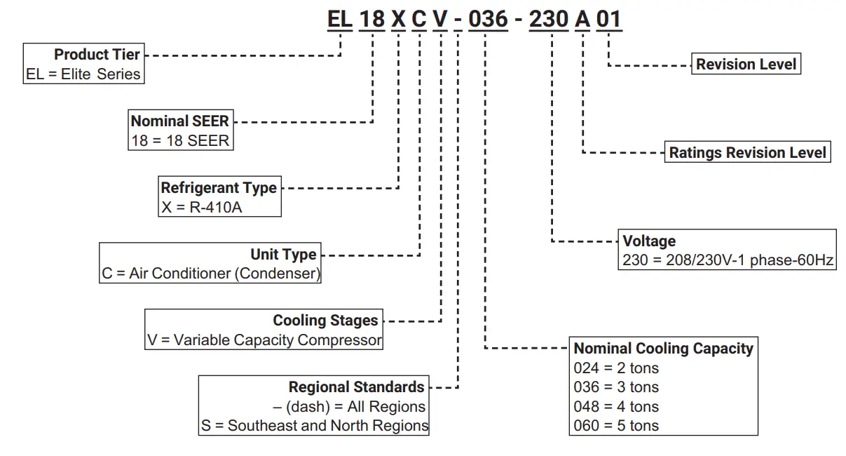
Model Number Identification
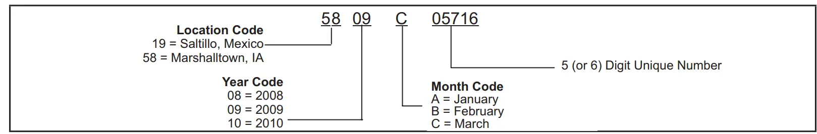
Typical Serial Number Identification
Specifications – All Regions
| General Model No. – All Regions Data Nominal Tonnage | ELI8XCV-024 | ELI8XCV-036 | ELI8XCV-048 | ELI8XCV-060 |
| 2 | 3 | 4 | 5 | |
| Connections Liquid line (o.d.) – in. (sweat) Suction line (o.d.) – in. | 3/8 | 3/8 | 3/8 | 3/8 |
| 3/4 | 7/8 | 7/8 | 1-1/8 | |
| Refrigerant ‘ R-410A charge furnished | 5 lbs. 7 oz. | 7 lbs. 6 oz. | 10 lbs. 7 oz. | 11 lbs. 8 oz. |
| Compressor Type | Rotary | Rotary | Rotary | Scroll |
| Outdoor Net face area – sq. ft. Outer coil Coil Inner coil Tube diameter – in. No. of rows Fins per inch | 14. | 14. | 24. | 27. |
| – – – | 14. | 23. | 26. | |
| 5/16 | 5/16 | 5/16 | 5/16 | |
| 1 | 2 | 2 | 2 | |
| 26 | 22 | 22 | 22 | |
| Outdoor Diameter – in. Fan No. of blades Motor hp Cfm Rpm Watts | 18 | 18 | 22 | 26 |
| 4 | 4 | 4 | 3 | |
| 1/5 | 1/5 | 1/4 | 1/3 | |
| 2500 | 2500 | 3560 | 4350 | |
| 1075 | 1075 | 825 | 1200 | |
| 183 | 183 | 278 | 252 | |
| Shipping Data – lbs. 1 pkg. | 180 | 195 | 270 | 298 |
Electrical Data
| Line Voltage Data – 60Hz | 208/230V-1ph | 208/230V-1ph | 208/230V-1ph | 208/230V-1ph |
| 2 Maximum Overcurrent Protection (amps) | 20 | 30 | 40 | 50 |
| 3 Minimum Circuit Ampacity | 12. | 18. | 24. | 30. |
| Compressor Input (amps) | 9. | 14. | 18. | 22. |
| Outdoor Fan Motor – Full Load Amps | 1. | 1. | 2. | 3. |
CONTROLS
| iComfort® S30 Ultra-Smart Wi-Fi Thermostat 19V30 | • | • | • | • |
| 4 Discharge Air Temperature Sensor 88K38 | • | • | • | • |
| iComfort® E30 Smart Wi-Fi Thermostat 20A65 | • | • | • | • |
OPTIONAL ACCESSORIES – ORDER SEPARATELY
| S Freezestat | 93G35 50A93 | • | • | • | • |
| • | • | • | • | ||
| Refrigerant Line Sets | L15-41-20 L15-41-40 L15-41-30 L15-41-50 | • | |||
| L15-65-30 L15-65-40 L15-65-50 | • | • | |||
| Field Fabricate | • |
NOTE – Extremes of operating range are plus 10% and minus 5% of line voltage.
- Refrigerant charge sufficient for 15 ft. length of refrigerant lines. For longer line set requirements see the Installation Instructions for information about line set length and additional refrigerant charge required.
- HACR type breaker or fuse.
- Refer to the National or Canadian Electrical Code manual to determine wire, fuse and disconnect size requirements.
- Used with the iComfort® S30 Ultra-Smart Wi-Fi Thermostat for optional service diagnostics.
- Freezestat is recommended for low ambient operation.
Specifications – Southeast and North Regions
| General Model No. – Southeast and North Regions Data Nominal Tonnage | EL18XCVS024 | EL18XCVS036 | EL18XCVSO48 | EL18XCVS060 |
| 2 | 3 | 4 | 5 | |
| Connections Liquid line (o.d.) – in. (sweat) Suction line (o.d.) – in. | 3/8 | 3/8 | 3/8 | 3/8 |
| 3/4 | 7/8 | 7/8 | 1-1/8 | |
| Refrigerant I R-410A charge furnished | 5 lbs. 7 oz. | 5 lbs. 11 oz. | 10 lbs. 7 oz. | 11 lbs. 10 oz. |
| Compressor Type | Rotary | Rotary | Rotary | Rotary |
| Outdoor Net face area – sq. ft. Outer coil Coil Inner coil Tube diameter – in. No. of rows Fins per inch | 14. | 14. | 24. | 24. |
| 23. | 23. | |||
| 5/16 | 5/16 | 5/16 | 5/16 | |
| 1 | 1 | 2 | 2 | |
| 26 | 26 | 22 | 22 | |
| Outdoor Diameter – in. Fan No. of blades Motor hp Cfm Rpm Watts | 18 | 18 | 22 | 22 |
| 4 | 4 | 4 | 4 | |
| 1/5 | 1/5 | 1/4 | 1/4 | |
| 2500 | 2400 | 3660 | 3650 | |
| 1075 | 1075 | 825 | 825 | |
| 183 | 187 | 278 | 278 | |
| Shipping Data – lbs. 1 pkg. | 180 | 180 | 270 | 270 |
| Line Voltage Data – 60Hz | 208/230V-1 ph | 208/230V-1 ph | 208/230V-1 ph | 208/230V-1 ph |
| 2 Maximum Overcurrent Protection (amps) | 20 | 30 | 40 | 50 |
| 3 Minimum Circuit Ampacity | 12. | 18. | 24. | 30. |
| Compressor Input (amps) | 9. | 14. | 18. | 23. |
| Outdoor Fan Motor – Full Load Amps | 1. | 1. | 2. | 2. |
CONTROLS
| iComfort”® S30 Ultra-Smart Wi-Fi Thermostat 19V30 | • | • | • | • |
| 4 Discharge Air Temperature Sensor 88K38 | • | • | • | • |
| iComfort”® E30 Smart Wi-Fi Thermostat 20A65 | • | • | • | • |
OPTIONAL ACCESSORIES – ORDER SEPARATELY
| 5 Freezestat | 93G35 50A93 | • | • | • | • |
| • | • | • | • | ||
| Refrigerant Line Sets | L15-41-20 L15-41-40 L15-41-30 L15-41-50 | • | |||
| L15-65-30 L15-65-40 L15-65-50 | • | • | |||
| Field Fabricate | • |
NOTE – Extremes of operating range are plus 10% and minus 5% of line voltage.
- Refrigerant charge sufficient for 15 ft. length of refrigerant lines. For longer line set requirements see the Installation Instructions for information about line set length and additional refrigerant charge required.
- HACR type breaker or fuse.
- Refer to the National or Canadian Electrical Code manual to determine wire, fuse, and disconnect size requirements.
- Used with the iComfort® S30 Ultra-Smart Wi-Fi Thermostat for optional service diagnostics.
- Freezestat is recommended for low ambient operation.
Unit Dimensions – Inches (mm) 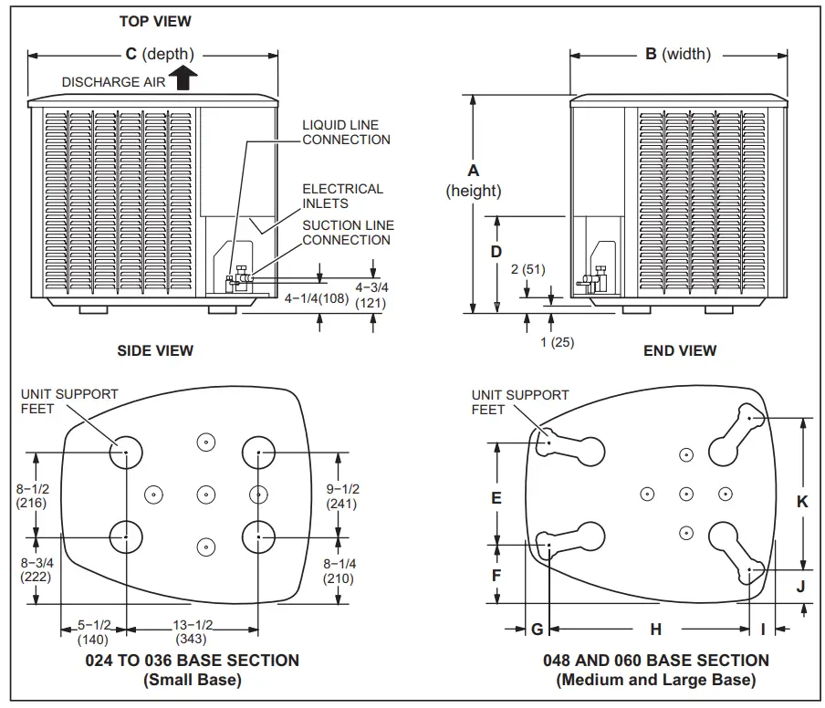
| Model | A(Height) | B(Width) | C(Depth) | D | E | F | G | H | I | J | K | |||||||||||
| in. | mm | in. | mm | in. | mm | in. | mm | in. | mm | in. | mm | in. | mm | in. | mm | in. | mm | in. | mm | in. | mm | |
| -024, S024 | 35 | 889 | 27 | 686 | 28 | 711 | 8 | 203 | – – – | – – – | – – – | – – – | – – – | – – – | – – – | – – – | – – – | – – – | – – – | – – – | – – – | – – – |
| -036, S036 | 35 | 889 | 27 | 686 | 28 | 711 | 8 | 203 | – – – | – – – | – – – | – – – | – – – | – – – | – – – | – – – | – – – | – – – | – – – | – – – | – – – | – – – |
| -048, S048 | 45 | 1143 | 30-1/2 | 775 | 35 | 889 | 11-5/8 | 295 | 13-7/8 | 352 | 7-3/4 | 197 | 3-1/4 | 83 | 27-1/8 | 689 | 3-5/8 | 92 | 4-1/2 | 114 | 20-5/8 | 524 |
| S060 | 45 | 1143 | 30-1/2 | 775 | 35 | 889 | 11-5/8 | 295 | 13-7/8 | 352 | 7-3/4 | 197 | 3-1/4 | 83 | 27-1/8 | 689 | 3-5/8 | 92 | 4-1/2 | 114 | 20-5/8 | 524 |
| -060 | 45 | 1143 | 351/2 | 902 | 391/2 | 1003 | 115/8 | 295 | 167/8 | 429 | 83/4 | 222 | 31/8 | 79 | 303/4 | 781 | 45/8 | 117 | 33/4 | 95 | 267/8 | 683 |
Typical Unit Parts Arrangement
Operating Gauge Set and Service Valves
TORQUE REQUIREMENTS
When servicing or repairing heating, ventilating, and air conditioning components, ensure the fasteners are appropriately tightened. Table 1 lists torque values for fasteners.
|
| Only use Allen wrenches of sufficient hardness (50Rc – Rockwell Harness Scale minimum). Fully insert the wrench into the valve stem recess. Service valve stems are factory-torqued (from 9 ft-lbs for small valves to 25 ft-lbs for large valves) to prevent refrigerant loss during shipping and handling. Using an Allen wrench rated at less than 50Rc risks rounding or breaking off the wrench, or stripping the valve stem recess. See the Lennox Service and Application Notes #C-08-1 for further details and information. |
|
| To prevent stripping of the various caps used, the appropriately sized wrench should be used and fitted snugly over the cap before tightening. |
TABLE 1. Torque Requirements
| Parts | Recommended Torque | |
| Service valve cap | 8 ft.- lb. | 11 NM |
| Sheet metal screws | 16 ft.- lb. | 2 NM |
| Machine screws #10 | 28 ft.- lb. | 3 NM |
| Compressor bolts | 90 in.- lb. | 10 NM |
| Gauge port seal cap | 8 ft.- lb. | 11 NM |
USING MANIFOLD GAUGE SET
When checking the system charge, only use a manifold gauge set that features low loss anti-blow back fittings.
Manifold gauge set used with HFC-410A refrigerant systems must be capable of handling the higher system operating pressures. The gauges should be rated for use with pressures of 0 – 800 psig on the high side and a low side of 30” vacuum to 250 psig with dampened speed to 500 psi. Gauge hoses must be rated for use at up to 800 PSIG of pressure with a 4000 psi burst rating.
OPERATING SERVICE VALVES
The liquid and vapor line service valves are used for removing refrigerant, flushing, leak testing, evacuating, checking charge, and charging. Each valve is equipped with a service port that has a factory-installed valve stem. Figure 4 provides information on access and operation of both angle and ball service valves
SERVICE VALVES ANGLE AND BALL
Operating Angle Type Service Valve:
- Remove the stem cap with an appropriately sized wrench.
Use a service wrench with a hex-head extension (3/16” for liquid line valve sizes and 5/16” for vapor line valve sizes) to back the stem out counterclockwise as far as it will go.
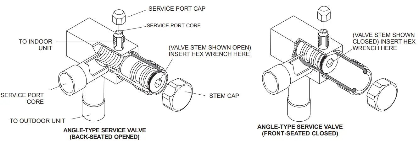
When the service valve is OPEN, the service port is open to the linE set, indoor and outdoor unit.
WHEN THE SERVICE VALVE IS CLOSED, THE SERVICE PORT IS OPEN TO THE LINE SET AND INDOOR UNIT.
Operating Ball Type Service Valve:
1. Remove the stem cap with an appropriately sized wrench.
2. Use an appropriately sized wrenched to open. To open the valve, rotate the stem counterclockwise 90°. To close rotate the stem clockwise 90°.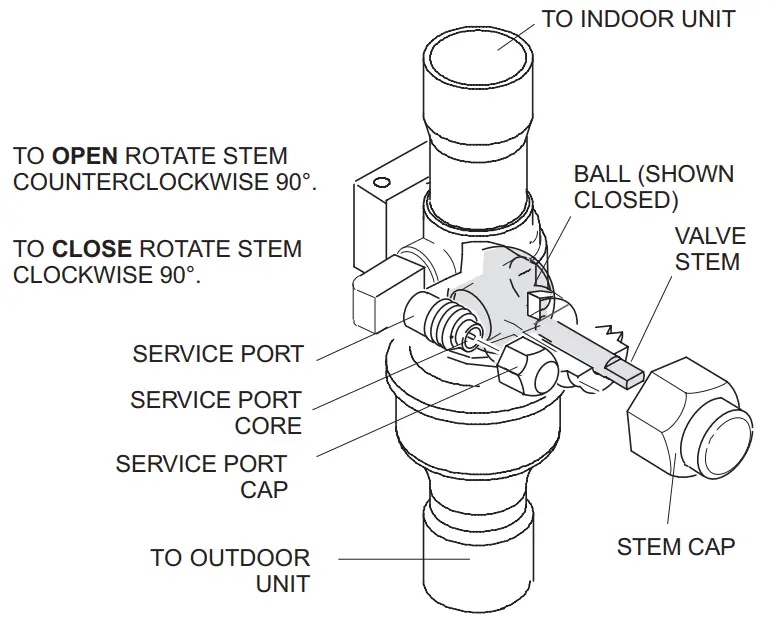
To Access Service Port:
A service port cap protects the service port core from contamination and serves as the primary leak seal.
- Remove the service port cap with an appropriately sized wrench.
- Connect gauge set to the service port.
- When testing is completed, replace the service port cap and tighten as follows:

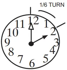
With torque wrench: Finger tightens and torque cap per table 3.
Without torque wrench: Finger tightens and uses an appropriately sized wrench to turn an additional 1/6 turn clockwise.
Reinstall Stem Cap:
The stem cap protects the valve stem from damage and serves as the primary seal. Replace the stem cap and tighten as follows:
With Torque Wrench: Finger tightens and then torque cap per table 3.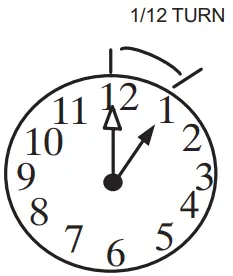 Without Torque Wrench: Finger tightens and use an appropriately sized wrench to turn an additional 1/12 turn clockwise.
NOTE — A label with specific torque requirements may be affixed to the stem cap. If the label is present, use the specified torque.
FIGURE 4. Angle and Ball Service Valves
Installation
Unit Placement
See Unit Dimensions on page 5 for sizing mounting slab, platforms or supports.
CAUTION
In order to avoid injury, take proper precautions when lifting heavy objects..
POSITIONING CONSIDERATIONS
Consider the following when positioning the unit:
- Some localities are adopting sound ordinances based on the unit’s sound level registered from the adjacent property, not from the installation property. Install the unit as far as possible from the property line.
- When possible, do not install the unit directly outside a window. Glass has a very high level of sound trans- mission. For proper placement of unit in relation to a window see the provided illustration in figure 6, detail A.
PLACING UNIT ON SLAB
When installing the unit at grade level, the top of the slab should be high enough above grade so that water from the higher ground will not collect around the unit. The slab should have a slope tolerance as described in figure 6, detail B. NOTE – If necessary for stability, anchor unit to slab as described in figure 6, detail D.
ELEVATING THE UNIT
Units are outfitted with elongated support feet as illustrated in figure 6, detail C.
If the additional elevation is necessary, raise the unit by extending the height of the unit support feet. Use a 2-inch (50.8mm) Schedule 40 female threaded adapter to raise the height of the unit. The specified coupling will fit snugly into the recessed portion of the feet. Use additional2-inch (50.8mm) Schedule 40 male threaded adaptors which can be threaded into the female threaded adaptors to make additional adjustments to the level of the unit.
NOTE – Keep the height of extenders short enough to ensure a sturdy installation. If it is necessary to extend the height further than what is stable, consider a different type of field-fabricated framework that is sturdy enough for greater heights.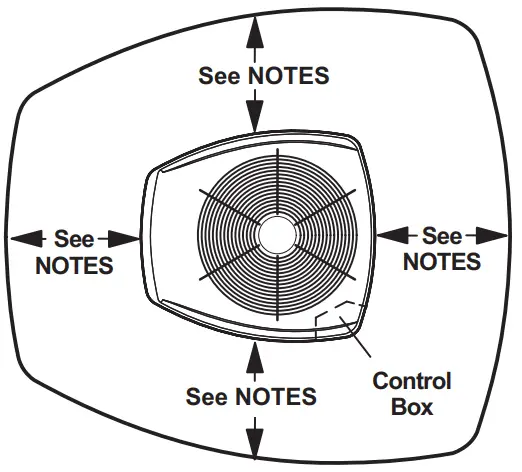
NOTES:
Service clearance of 30 in. must be maintained on one of the sides adjacent to the control box.
Clearance to one of the other three sides must be 36 in.
Clearance to one of the remaining two sides may be 12 in. and the final side maybe 6 in.
A clearance of 24 in. must be maintained between two units. 48 in. clearance required on top of the unit.
NOTICE: Specific applications may require adjustment of the listed installation clearances to provide protection for the unit from physical damage or to avoid conditions that limit operating efficiency. (Example: Clearances may have to be increased to prevent snow or ice from falling on the top of the unit. Additional clearances may also be
required to prevent air recirculation when the unit is installed under a deck or in another tight space.)
FIGURE 5. Installation Clearances.
STABILIZING UNIT ON UNEVEN SURFACES![]() IMPORTANT
IMPORTANT
Unit Stabilizer Bracket Use (field-provided):
Always use stabilizers when the unit is raised above the factory height. (Elevated units could become unstable in gusty wind conditions.)
Stabilizers may be used on factory height units when mounted on unstable and uneven surfaces..
- Remove the louvered panel from each side to expose the unit base.
- Install the brackets as illustrated in figure 6, detail D using conventional practices.
- Replace the panels after installation is complete.
ROOF MOUNTING
Locate the unit above a load-bearing wall or area of the roof that can adequately support the unit. Consult local codes for rooftop applications.![]() NOTICE
NOTICE
Roof Damage!
This system contains both refrigerant and oil. Some rubber roofing material may absorb oil, causing the rubber to swell. Bubbles in the rubber roofing material can cause leaks. Protect the roof surface to avoid exposure to refrigerant and oil during service and installation. Failure to follow this notice could result in damage to the roof surface.
DETAIL A
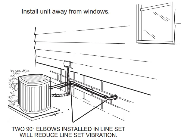
Outside Unit Placement
DETAIL B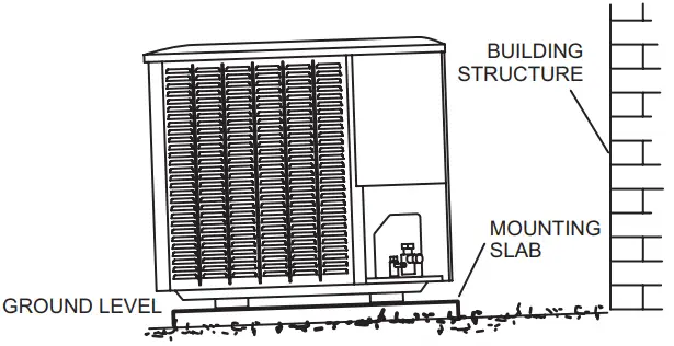
Slab Mounting at Ground Level
DETAIL C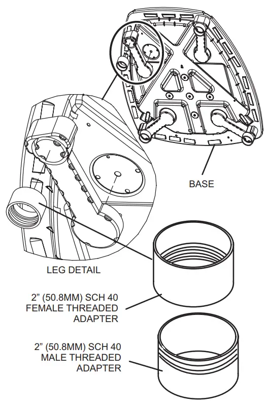
USE ADDITIONAL 2″ SCH 40 MALE THREADED ADAPT-ERS WHICH CAN BE THREADED INTO THE FEMALE THREADED ADAPTERS TO MAKE ADDITIONAL ADJUSTMENTS TO THE LEVEL OF THE UNIT.
Elevated Slab Mounting using Feet Extenders
DETAIL B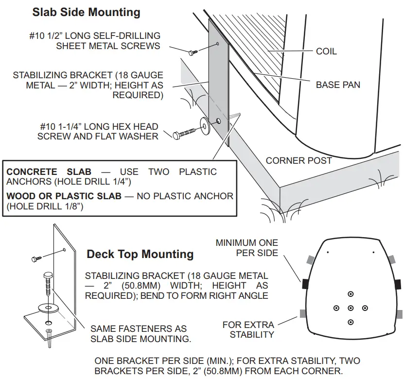
ONE BRACKET PER SIDE (MIN.); FOR EXTRA STABILITY, TWO BRACKETS PER SIDE, 2″ (50.8MM) FROM EACH CORNER.
Stabilizing Unit on Uneven Surfaces
IMPORTANT – To help stabilize an outdoor unit, some installations may require strapping the unit to the pad using brackets and anchors commonly available in the marketplace.
FIGURE 6. Placement and Slab Mounting
Removing and Installing Panels
LOUVERED PANEL REMOVAL Remove the louvered panels as follows:
- Remove two screws, allowing the panel to swing open slightly.
- Hold the panel firmly throughout this procedure. Rotate the bottom corner of the panel away from the hinged corner post until lower three tabs clear the slots as illustrated in Detail B.
- Move panel down until lip of the upper tab clears the top slot in the corner post as illustrated in Detail A.
LOUVERED PANEL INSTALLATION Position the panel almost parallel with the unit as illustrated in Detail D with the screw side as close to the unit as possible. Then, in a continuous motion:
- Slightly rotate and guide the lip of the top tab inward as illustrated in details A and C; then upward into the top slot of the hinge corner post.
- Rotate the panel until it is completely vertical to fully engage all of the tabs.
- Holding the panel’s hinged side firmly in place, close the right-hand side of the panel, aligning the screw holes.
- When the panel is correctly positioned and aligned, insert the screws and tighten them.
IMPORTANT! DO NOT ALLOW PANELS TO HANG ON THE UNIT BY THE TOP TAB. TAB IS FOR ALIGNMENT AND IS NOT DESIGNED TO SUPPORT THE WEIGHT OF THE PANEL.
PANEL SHOWN SLIGHTLY ROTATED TO ALLOW TOP TAB TO EXIT (OR ENTER) TOP SLOT FOR REMOVING (OR INSTALLING) PANEL. 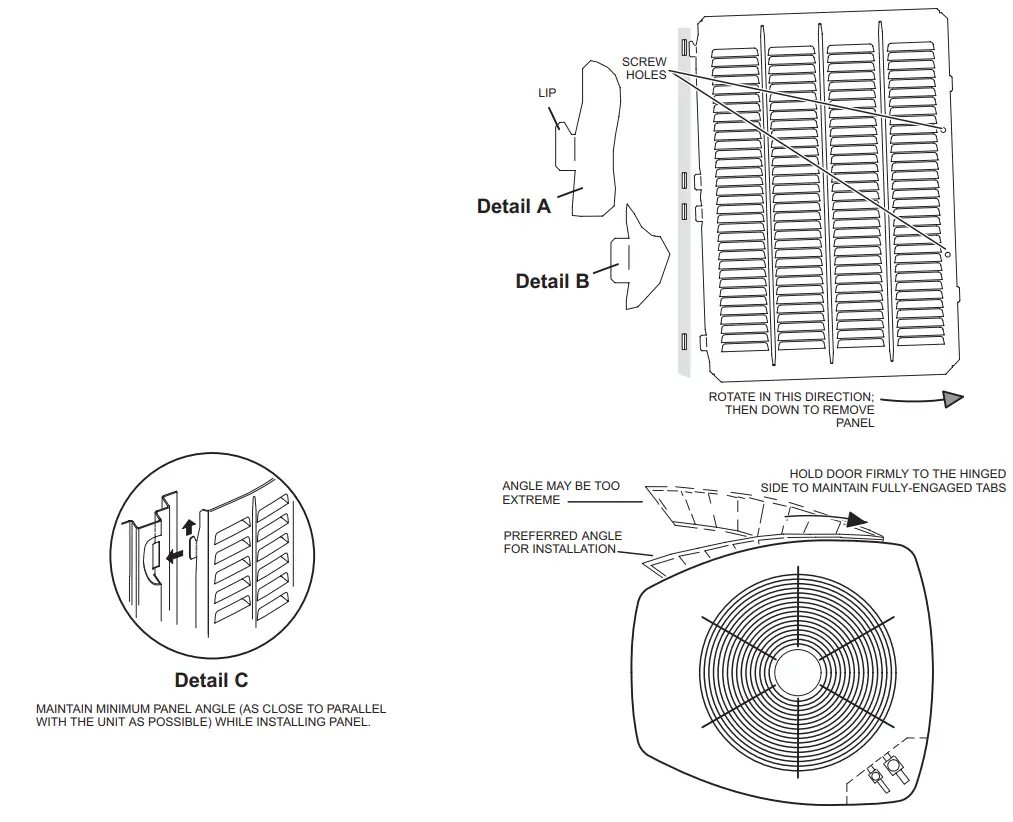
FIGURE 7. Removing and Installing Panels
New or Replacement Line Set
IMPORTANT
If this unit is being matched with an approved line set or indoor unit coil that was previously charged with mineral oil, or if it is being matched with a coil that was manufactured before January of 1999, the coil and line set must be flushed prior to installation. Take care to empty all existing traps. Polyvinyl ether (PVE) and polyol ester (POE) oils are used in Lennox variable-capacity units charged with HFC-410A refrigerant. Residual mineral oil can act as an insulator, preventing proper heat transfer. It can also clog the expansion device and reduce system performance and capacity. Failure to properly flush the system per this instruction and the detailed Installation and Service Procedures manual will void the warranty.
Flush the existing line set per the following instructions. For more information, refer to the Installation and Service Procedures manual available on LennoxPros.com. CAUTION
– DO NOT attempt to flush and re-use existing line sets or indoor coil when the system contains contaminants (i.e., compressor burnout).
Polyvinyl ether (PVE) oil is used in the EL18XCVS024, S036, S048, S060, EL18XCV-024, -036, and -048 with rotary compressors.
For installations of the EL18XCVS024, S036, S048, S060, EL18XCV-024, -036, and -048 units with refrigerant lines or coils previously charged with R410A and POE oil, Lennox recommends flushing the existing lines and coil with R410A refrigerant to remove excess POE oil that may be in the system. The EL18XCV-060 air conditioners have variable capacity scroll compressors that use POE oil. EL18XCV-060 units with refrigerant lines or coils previously charged with R410A and POE oil, do not need to be flushed to remove the POE oil.
If a new line set is being installed, size the piping per table 1.
TABLE 2
| REFRIGERANT LINE SET – INCHES (MM) | |||||
| Model | Valve Field Connections | Recommended Line Set | |||
| Liquid Line | Vapor Line | Liquid Line | Vapor Line | L15 Line Sets | |
| -024 | 3/8 in. (10 mm) | 3/4 in. (19 mm) | 3/8 in. (10 mm) | 3/4 in. (19 mm) | L15-41 15 ft. – 50 ft. (4.6 m – 15 m) |
| -036 | 3/8 in. (10 mm) | 7/8 in. (22 mm) | 3/8 in. (10 mm) | 7/8 in. (22 mm) | L15-65 15 ft. – 50 ft. (4.6 m – 15 m) |
| -048 | |||||
| -060 | 3/8 in. (10 mm) | 1-1/8 in. (28 mm) | 3/8 in. (10 mm) | 1-1/8 in. (28 mm) | Field Fabricated |
| NOTE – Some applications may require a field-provided 7/8″ to 1-1/8″ adapter. | |||||
NOTE – When installing refrigerant lines longer than 50 feet, refer to the Refrigerant Piping Design and Fabrication
Guidelines manual available on LennoxPros.com
(Corp. 9351-L9), or contact the Technical Support Department Product
Application group for assistance.
NOTE – For new or replacement line set installation, refer to Service and Application Note – Corp. 9112-L4 (C-91-4).![]() WARNING
WARNING![]() When using a high-pressure gas such as nitrogen to pressurize refrigeration or air conditioning system, use a regulator that can control the pressure down to 1 or 2 psig (6.9
When using a high-pressure gas such as nitrogen to pressurize refrigeration or air conditioning system, use a regulator that can control the pressure down to 1 or 2 psig (6.9
to 13.8 kPa).![]() WARNING
WARNING
Refrigerant can be harmful if it is inhaled. Refrigerant must be used and recovered responsibly. Failure to follow this warning may result in personal injury or death.![]() WARNING
WARNING![]() Fire, Explosion, and Personal Safety hazard. Failure to follow this warning could result in damage, personal injury or death.
Fire, Explosion, and Personal Safety hazard. Failure to follow this warning could result in damage, personal injury or death.
Never use oxygen to pressurize or purge refrigeration lines. Oxygen, when exposed to a spark or open flame, can cause fire and/ or an explosion, that could result in property
damage, personal injury, or death.![]() WARNING
WARNING
Polyvinyl ether (PVE) oils used with HFC-410A refrigerants absorb moisture very quickly. It is very important that the refrigerant system be kept closed as much as possible.
DO NOT remove line set caps or service valve stub caps until you are ready to make connections.
The EL18XCV is a variable-capacity cooling system utilizing variable speed compressor technology. With the variable speed compressor and variable pumping capacity, additional consideration must be given to refrigerant piping sizing and application.
The guidelines below are to be used exclusively for the EL18XCV systems.
COOLING SYSTEM (HFC410A)
- Total equivalent length equals 180 feet (piping and all fittings included).
NOTE – Length is a general guide. Lengths may be more or less, depending on the remaining system design factors. - Maximum linear (actual) length = 150 feet.
- Maximum linear liquid lift = 60 feet.
NOTE – Maximum lifts are dependent on total length, number of elbows, etc. that contribute to total pressure drop. - Maximum length vapor riser = 60 feet.
- Up to 50 Linear Feet: Use rated line sizes listed in table 1.
- Between 51 and 150 Linear Feet: Crankcase heater and non bleed port TXV factory installed. No additional components are required. The vertical vapor riser must be sized to the vapor riser listed in table 2 on systems with line sets longer than 51 feet. Use tables 2 and 3 to determine the correct liquid and vapor line sizes.
- Over 150 Linear Feet: not recommended.
- Additional oil is not required for systems with line lengths up to 150 feet.
SUCTION TRAPS
For systems with the outdoor unit 5 – 60 feet above the indoor unit, one trap must be installed at the bottom of the suction riser.
TABLE 3. Standard Refrigerant Line Set – Up to 50 Linear Feet in Length
| Inches (mm) | |||||
| Valve Size Connections | Recommended Line Sets | ||||
| EL18XCV* | Liquid Line | Suction Line | L15 Line Set Model | Line Set Length | Catalog Number |
| -024, S024 | 3/8” (10 mm) | 3/4” (19 mm) | L15-41-30 | 30 feet (9.1 m) | 89J60 |
| -036, S036 -048, S048 | 3/8” (10 mm) | 7/8” (22 mm) | L15-65-40 | 40 feet (12.2 m) | 89J61 |
| L15-65-50 | 50 feet (15.2 m) | 89J62 | |||
| -060, S060 | 3/8” (10 mm) | 1-1/8” (29 mm) ** | Field-fabricated | ||
* Applicable to all minor revision numbers unless otherwise specified.
** Some applications may require a field-provided 1-1/8” to 7/8” adapter.
TABLE 4. EL18XCV Line Set Guidelines – 51 to 150 Linear Feet in Length
| Model | Maximum Total Equivalent Length (ft) | Maximum Linear (actual) Length (ft) | Maximum Vapor Riser (ft) | Maximum Linear Liquid Lift (ft) | Preferred Vapor Line Sizes for Horizontal Runs | Required Vapor Riser Size |
| 180 | 150 | 60 | 60 | 7/8” | 5/8” | |
| 180 | 150 | 60 | 60 | 7/8” | 3/4” | |
| 180 | 150 | 60 | 60 | 7/8” | 7/8” | |
| 180 | 150 | 60 | 60 | 7/8” | 7/8” |
TABLE 5. Liquid Line Diameter Selection Table
| Unit | Line Size | Total Linear Length (feet) | ||||||
| 25 | 50 | 75 | 100 | 125 | 150 | |||
| 5/16” | 25 | 50 | 55 | 48 | 40 | 33 | Max. Elevation (ft) | |
| 3/8” | 25 | 50 | 60 | 60 | 60 | 60 | ||
| 3/8” | 25 | 50 | 60 | 56 | 51 | 45 | ||
| 1/2” | 25 | 50 | 60 | 60 | 60 | 60 | ||
| 3/8” | 25 | 50 | 50 | 41 | 31 | 22 | ||
| 1/2” | 25 | 50 | 60 | 60 | 60 | 60 | ||
| 3/8” | 25 | 50 | 36 | 22 | 8 | NR | ||
| 1/2” | 25 | 50 | 60 | 60 | 60 | 59 | ||
NOTE Shaded rows indicate rated liquid line size
A. Find your unit on the left side of the table.
B. Start with the rated liquid line size (shaded row) on the outdoor unit
C. Select the actual Total Linear Length of your system shown at the top of the table.
D. The elevation listed in the table is the maximum allowed for the liquid line listed.
E. Select or consider the larger liquid line size shown in the table if the elevation does not meet your requirements.
NOTE – For new or replacement line set installation, refer to Service and Application Note – Corp. 9112-L4 (C-91-4).
LINE SET
IMPORTANT — Refrigerant lines must not contact structure.
INSTALLATION
Line Set Isolation — The following illustrations are examples of proper refrigerant line set isolation:
REFRIGERANT LINE SET — TRANSITION FROM VERTICAL TO HORIZONTAL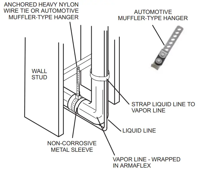
REFRIGERANT LINE SET — INSTALLING HORIZONTAL RUNS
To hang line set from joist or rafter, use either metal strapping material or anchored heavy nylon wire ties.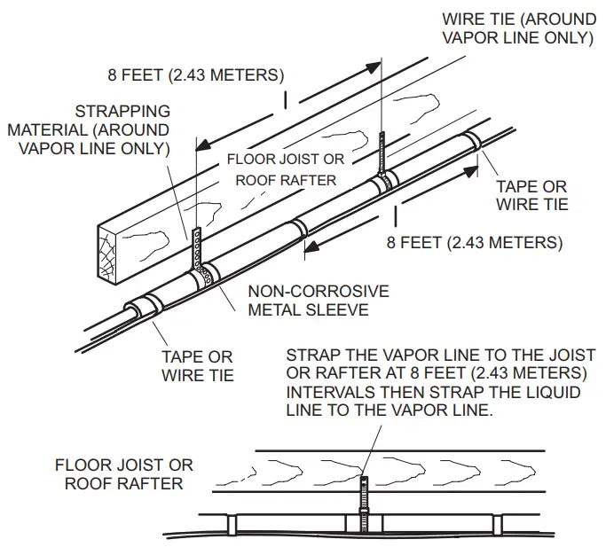
REFRIGERANT LINE SET — INSTALLING VERTICAL RUNS (NEW CONSTRUCTION SHOWN)
NOTE — Insulate the liquid line when it is routed through areas where the surrounding ambient temperature could become higher than the temperature of the liquid line or when the pressure drop is equal to or greater than 20 psi.
IMPORTANT — Refrigerant lines must not contact the wall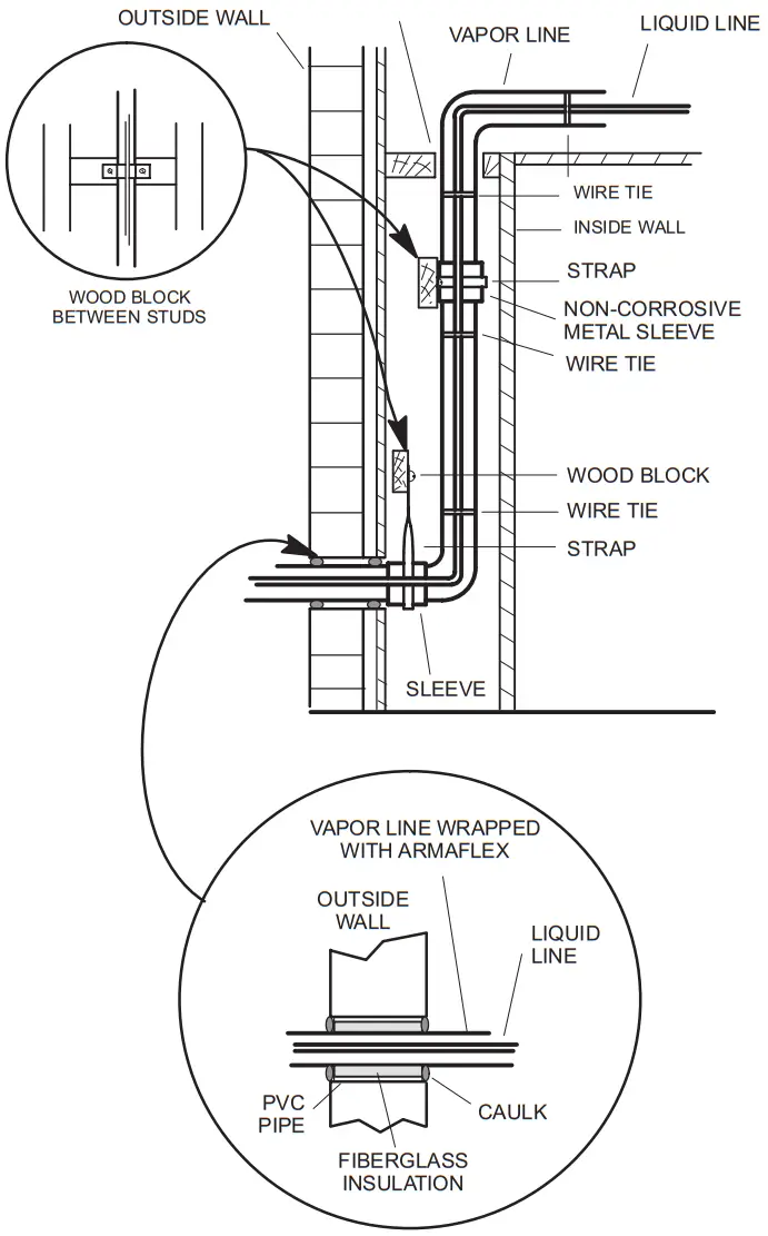
NOTE — Similar installation practices should be used if a line set is to be installed on the exterior of the outside wall.
WARNING — Polyol ester (POE) oils used with HFC-410A refrigerant absorb moisture very quickly. It is very important that the refrigerant system be kept closed as much as possible. DO NOT remove line set caps or service valve stub caps until you are ready to make connections.
Brazing Connections
Use the procedures outlined in figures 5 and 6 for brazing line set connections to service valves.![]() WARNING
WARNING![]() The danger of fire. Bleeding the refrigerant charge from only the high side may result in pressurization of the low side shell and suction tubing. Application of a brazing torch
The danger of fire. Bleeding the refrigerant charge from only the high side may result in pressurization of the low side shell and suction tubing. Application of a brazing torch
to a pressurized system may result in ignition of the refrigerant and oil mixture. Check the high and low pressures before applying heat.![]() WARNING
WARNING![]() When using a high-pressure gas such as nitrogen to pressurize a refrigeration or air conditioning system, use a regulator that can control the pressure down to 1 or 2 psig (6.9
When using a high-pressure gas such as nitrogen to pressurize a refrigeration or air conditioning system, use a regulator that can control the pressure down to 1 or 2 psig (6.9
to 13.8 kPa).![]() CAUTION
CAUTION
Brazing alloys and flux contain materials which are hazardous to your health.
Avoid breathing vapors or fumes from brazing operations. Perform operations only in well-ventilated areas.
Wear gloves and protective goggles or a face shield to protect against burns.
Wash hands with soap and water after handling brazing alloys and flux.![]() IMPORTANT
IMPORTANT
Allow the brazing joint to cool before removing the wet rag from the service valve. Temperatures above 250ºF can damage valve seals.![]() IMPORTANT
IMPORTANT
Use silver alloy brazing rods with 5% minimum silver alloy for copper-to-copper brazing. Use 45% minimum alloy for copper-to-brass and copper-to-steel brazing.![]() WARNING
WARNING![]() Fire, Explosion, and Personal Safety hazard. Failure to follow this warning could result in damage, personal injury or death. Never use oxygen to pressurize or purge refrigeration lines. Oxygen, when exposed to a spark or open flame, can cause fire and/ or an explosion, that could result in property damage, personal injury or death.
Fire, Explosion, and Personal Safety hazard. Failure to follow this warning could result in damage, personal injury or death. Never use oxygen to pressurize or purge refrigeration lines. Oxygen, when exposed to a spark or open flame, can cause fire and/ or an explosion, that could result in property damage, personal injury or death.
PIPING PANEL REMOVAL AND LINE SET PREPARATION
Remove piping panel for easier access to service valves. Cut ends of the refrigerant lines square (free from nicks or dents) and deburr the ends. The pipe must remain round. Do not crimp the end of the line.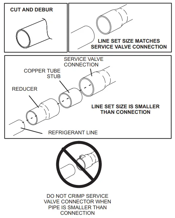
CAP AND CORE REMOVAL
Remove service cap and core from both the suction and liquid line service ports.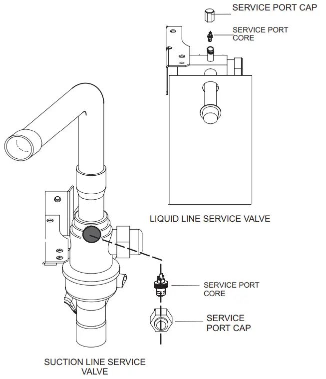
ATTACH THE MANIFOLD GAUGE SET FOR BRAZING LIQUID AND SUCTION LINE SERVICE VALVES
A. Connect gauge set low-pressure side to liquid line service valve (service port). B. Connect gauge set center port to a bottle of nitrogen with the regulator.
C. With the valve core removed from the suction line service port, nitrogen flow will have an exit point. 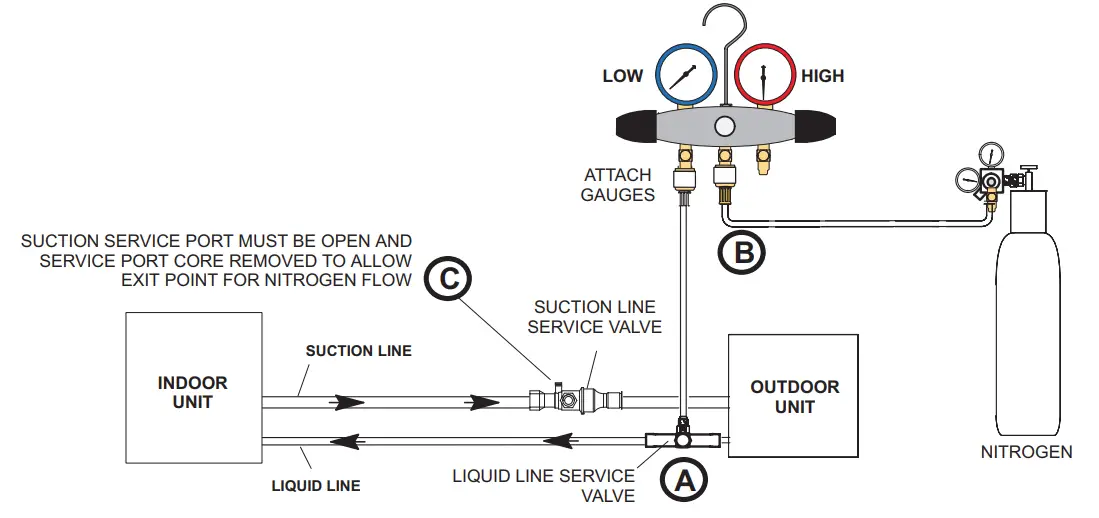
FIGURE 9. Brazing Procedures
WRAP SERVICE VALVES
To help protect service valve seals during brazing, wrap water-saturated cloths around service valve bodies and copper tube stubs. Use additional water-saturated cloths underneath the valve body to protect the base paint.
FLOW NITROGEN
Flow regulated nitrogen (at 1 to 2 psi) through the refrigeration gauge set into the valve stem port connection on the liquid service valve and out of the suction/vapor valve stem port. See steps 3A, 3B, and 3C on manifold gauge set connections.
BRAZE LINE SET
Wrap both service valves with water-saturated cloths as illustrated here and as mentioned in step 4, before brazing to the line set. Cloths must remain water-saturated throughout the brazing and cool-down process.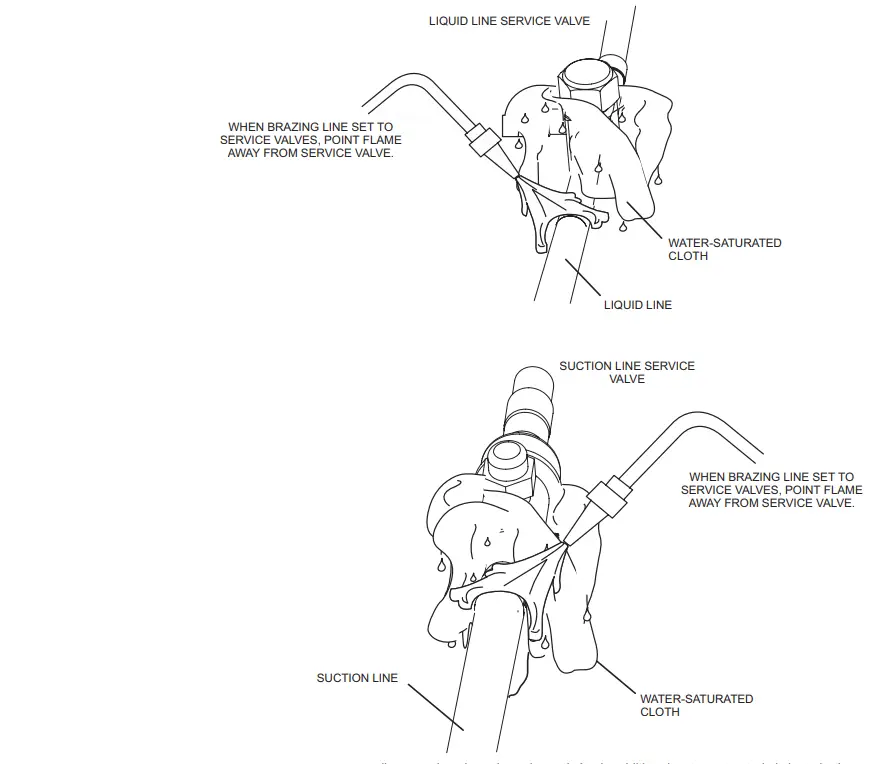
IMPORTANT – Allow braze joint to cool. Apply additional water-saturated cloths to help cool the brazed joint. Do not remove water-saturated cloths until the piping has cooled. Temperatures above 250ºF will damage valve seals.
WARNING![]() FIRE, PERSONAL INJURY, OR PROPERTY DAMAGE may result if you do not wrap a water-saturated cloth around both liquid and suction line service valve bodies and copper tube stub while brazing the line set! The braze, when complete, must be quenched with water to absorb any residual heat.
FIRE, PERSONAL INJURY, OR PROPERTY DAMAGE may result if you do not wrap a water-saturated cloth around both liquid and suction line service valve bodies and copper tube stub while brazing the line set! The braze, when complete, must be quenched with water to absorb any residual heat.![]() Do not open service valves until refrigerant lines and indoor coil have been leak-tested and evacuated. Refer to the Installation and Service Procedures manual found on LennoxPros.com.
Do not open service valves until refrigerant lines and indoor coil have been leak-tested and evacuated. Refer to the Installation and Service Procedures manual found on LennoxPros.com.
PREPARATION FOR THE NEXT STEP
Disconnect manifold gauge set from service ports after all connections have been brazed. Apply additional water-saturated cloths to both service valves to cool piping. Once the piping is cool, remove all water-saturated cloths.
FIGURE 10. Brazing Procedures (Cont’d)
Flushing Line Set and Indoor Coil
TYPICAL EXISTING FIXED ORIFICREMOVAL PROCEDURE (UNCASED COIL SHOWN)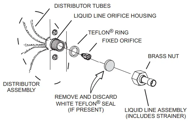
A.On fully cased coils. remove the coil access and plumbing panels.
B Remove any shipping damps holding the liquid line and distributor assembly.
C. Using two wrenches. disconnect the liquid line from the liquid line orifice housing. Take care not to twist or damage distributor tubes during this process.
D. Remove and discard fixed orifice. valve stem assembly if present and Teflon’s washer as illustrated above.
E. Use a field-provided fitting to temporarily reconnect the liquid line to the indoor unit’s liquid line orifice housing.
TYPICAL EXISTING EXPANSION VALVE REMOVAL PROCEDURE (UNCASED COIL SHOWN)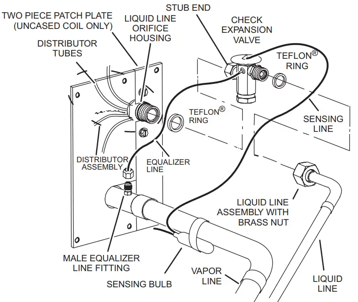 A. On fully cased coils, remove the coil access and plumbing panels.
B. Remove any shipping clamps holding the liquid line and distributor assembly.
C. Disconnect the equalizer line from the check expansion valve equalizer line fitting on the vapor line.
D. Remove the vapor line sensing bulb.
E. Disconnect the liquid line from the check expansion valve at the liquid line assembly.
F. Disconnect the check expansion valve from the liquid line orifice housing. Take care not to twist or damage distributor tubes during this process.
G. Remove and discard the check expansion valve and the two Teflon rings.
H. Use a field-provided fitting to temporarily reconnect the liquid line to the indoor unit’s liquid line orifice housing.
CONNECT GAUGES AND EQUIPMENT FOR THE FLUSHING PROCEDURE 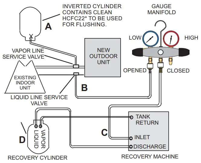
An Inverted HCFC-22 cylinder with clean refrigerant* to the vapor service valve.
B HCFC-22 gauge set (low side) to the liquid line valve.
C HCFC-22 gauge set center port to inlet on the recovery machine with an empty recovery tank to the gauge set.
D Connect recovery tank to recovery machines per machine instructions.
FLUSHING LINE SET
The line set and indoor unit coil must be flushed with at least the same amount of clean refrigerant* that previously charged the system. Check the charge in the flushing cylinder before proceeding.
A. Set the recovery machine for liquid recovery and start the recovery machine. Open the gauge set valves to allow the recovery machine to pull a vacuum on the existing system line set and indoor unit coil.
B. Invert the cylinder of clean HCFC-22* and open its valve to allow liquid refrigerant to flow into the system through the vapor line valve. Allow the refrigerant to pass from the cylinder and through the line set and the indoor unit coil before it enters the recovery machine.
C. After all of the liquid refrigerant has been recovered, switch the recovery machine to vapor recovery so that all of the HCFC-22 vapor is recovered. Allow the recovery machine to pull the system down to 0.
D. Close the valve on the inverted HCFC-22 drum and the gauge set valves. Pump the remaining refrigerant out of the recovery machine and turn the machine off.
*IMPORTANT – Clean refrigerant is any refrigerant in a system that has not had compressor burnout. If the system has experienced burnout, it is recommended that the existing line set and indoor coil be replaced.
FIGURE 11. Removing Metering Device and Flushing
FLUSHING LINE SET AND INDOOR COIL (2 OF 2)
TYPICAL NEW CHECK EXPANSION VALVE INSTALLATION PROCEDURE
THIS OUTDOOR UNIT IS DESIGNED FOR USE IN SYSTEMS THAT USE A CHECK EXPANSION VALVE METERING DEVICE. SEE THE UNIT
PRODUCT SPECIFICATIONS FOR APPROVED EXPANSION VALVE KIT MATCH-UPS AND APPLICATION INFORMATION.
THE EXPANSION VALVE UNIT CAN BE INSTALLED INTERNALLY OR EXTERNALLY TO THE INDOOR COIL. IN APPLICATIONS WHERE AN UNCASED COIL IS BEING INSTALLED IN A FIELD-PROVIDED PLENUM, INSTALL THE CHECK EXPANSION VALVE IN A MANNER THAT WILL PROVIDE ACCESS FOR FIELD SERVICING OF THE EXPANSION VALVE. REFER TO THE BELOW ILLUSTRATION FOR REFERENCE DURING THE INSTALLATION OF THE EXPANSION VALVE UNIT.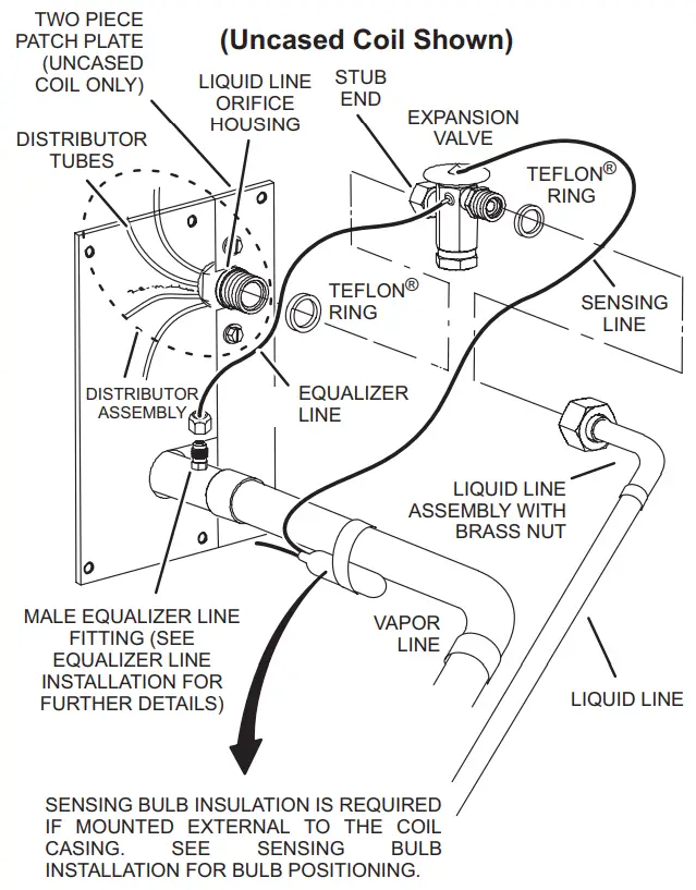 SENSING BULB INSTALLATION
A. ATTACH THE VAPOR LINE SENSING BULB IN THE PROPER ORIENTATION AS ILLUSTRATED TO THE RIGHT USING THE CLAMP AND SCREWS PROVIDED. NOTE – CONFIRM PROPER THERMAL CONTACT BETWEEN VAPOR LINE AND CHECK EXPANSION BULB BEFORE!NW-LA17NG THE SENSING BULB ONCE INSTALLED.
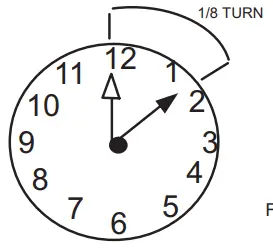 B. CONNECT THE EQUALIZER LINE FROM THE EXPANSION VALVE TO THE EQUALIZER VAPOR PORT ON THE VAPOR UNE. FINGER TIGHTEN THE FLARE NUT PLUS 118 TURNS (7 FT-LBS) AS ILLUSTRATED BELOW.
EQUALIZER LINE INSTALLATION
REMOVE AND DISCARD EITHER THE FLARE SEAL CAP OR FLARE NUT WITH COPPER FLARE SEAL BONNET FROM THE EQUALIZER LINE PORT ON THE VAPOR LINE AS ILLUSTRATED IN THE FIGURE TO THE RIGHT.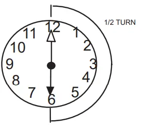 A. REMOVE THE FIELD-PROVIDED FITTING THAT TEMPORARILY RECONNECTED THE LIQUID LINE TO THE INDOOR wars DISTRIBUTOR AS-SEMBLY
B. INSTALL ONE OF THE PROVIDED TEFLON° RINGS AROUND THE STUBBED END OF THE EXPANSION VALVE AND LIGHTLY LUBRICATE THE CONNECTOR THREADS AND EXPOSE THE SURFACE OF THE TEFLON° RING WITH REFRIGERANT OIL.
C. ATTACH THE STUBBED END OF THE EXPANSION VALVE TO THE LIQUID LINE ORIFICE HOUSING. FINGER TIGHTEN MO USES AN APPROPRIATELY SIZED WRENCH TO TURN AN ADDITIONAL 12 TURNS CLOCKWISE AS ILLUSTRATED IN THE FIGURE ABOVE. OR 20 FT-U3.
D. PLACE THE REMAINING TEFLON° WASHER AROUND THE OTHER END OF THE EXPANSION VALVE. NIGHTLY LUBRICATE CONNECTOR THREADS AND EXPOSE THE SURFACE OF THE TEFLON° RING WITH REFRIGERANT OIL.
E. ATTACH THE LIQUID UNE ASSEMBLY TO THE EXPANSION VALVE. FIN-GER TIGHTEN AND USE AN APPROPRIATELY SIZED WRENCH TO TURN AN ADDITIONAL I2 TURN CLOCKWISE AS ILLUSTRATED IN THE FIGURE ABOVE OR 20 FT-LB.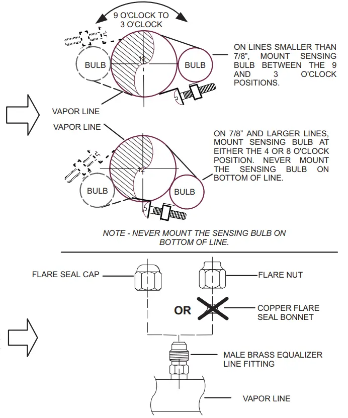
![]() IMPORTANT
IMPORTANT
The Environmental Protection Agency (EPA) prohibits the intentional venting of HFC refrigerants during maintenance, service, repair, and disposal of appliances. Approved methods of recovery, recycling, or reclaiming must be followed.![]() IMPORTANT
IMPORTANT
If this unit is being matched with an approved line set or indoor unit coil that was previously charged with mineral oil, or if it is being matched with a coil that was manufactured before January of 1999, the coil and line set must be flushed prior to installation. Take care to empty all existing traps. Polyvinyl ether (PVE) oils are used in Lennox variable-capacity units charged with HFC-410A refrigerant. Residual mineral oil can act as an insulator, preventing proper heat transfer. It can also clog the expansion device and reduce system performance and capacity. Failure to properly flush the system per this instruction and the detailed Installation and Service Procedures manual will void the warranty.
Leak Testing the System![]() WARNING
WARNING![]() When using a high-pressure gas such as nitrogen to pressurize refrigeration or air conditioning system, use a regulator that can control the pressure down to 1 or 2 psig (6.9 to 13.8 kPa).
When using a high-pressure gas such as nitrogen to pressurize refrigeration or air conditioning system, use a regulator that can control the pressure down to 1 or 2 psig (6.9 to 13.8 kPa).![]() IMPORTANT
IMPORTANT
A leak detector must be capable of sensing HFC refrigerant.![]() WARNING
WARNING
Refrigerant can be harmful if it is inhaled. Refrigerant must be used and recovered responsibly. Failure to follow this warning may result in personal injury or death.
LEAK TEST
LINE SET AND INDOOR COIL
A. CONNECT AN HFC-410A MANIFOLD GAUGE SET HIGH-PRESSURE HOSE TO THE VAPOR VALVE SERVICE PORT. CONNECT GAUGE SET
B. WITH BOTH MANIFOLD VALVES CLOSED, CONNECT THE CYLINDER OF HFC-410A REFRIGERANT TO THE CENTER PORT OF THE MANIFOLD GAUGE SET.
NOTE – LATER IN THE PROCEDURE, THE HFC-410A CONTAINER WILL BE REPLACED BY THE NITROGEN CONTAINER.
NOTE – NORMALLY, THE HIGH-PRESSURE HOSE IS CONNECTED TO THE LIQUID LINE PORT. HOWEVER, CONNECTING IT TO THE VAPOR PORT BETTER PROTECTS THE MANIFOLD GAUGE SET FROM HIGH-PRESSURE DAMAGE..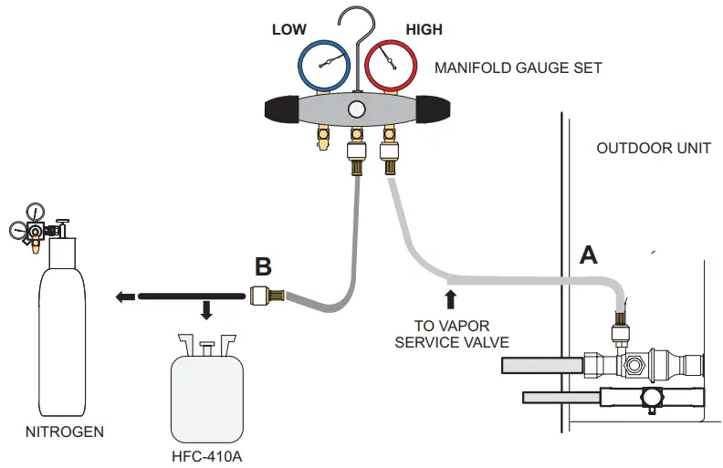
TEST FOR LEAKS
AFTER THE LINE SET HAS BEEN CONNECTED TO THE INDOOR AND OUTDOOR UNITS, CHECK THE LINE SET CONNECTIONS AND INDOOR UNIT FOR LEAKS. USE THE FOLLOWING PROCEDURE TO TEST FOR LEAKS:
A. WITH BOTH MANIFOLD VALVES CLOSED. CONNECT THE CYLINDER OF HFC-410A REFRIGERANT TO THE CENTER PORT OF THE MANIFOLD GAUGE SET. OPEN THE VALVE ON THE HFC-410A CYLINDER (VAPOR ONLY).
B. OPEN TEE HIGH-PRESSURE SIDE OF THE MANIFOLD TO ALLOW HFC-410A INTO THE LINE SET AND INDOOR UNIT WEIGH IN A TRACE AMOUNT OF HFC4IOA (A TRACE AMOUNT IS A MAXIMUM OF TWO OUNCES (57 G) REFRIGERANT OR THREE POUNDS (31 KPA) PRES-SURE]. CLOSE THE VALVE ON THE NE HFC-410A CYLINDER AND THE VALVE ON THE HIGH-PRESSURE SIDE OF THE MANIFOLD GAUGE SET. DISCONNECT THE HFC-410A CYLINDER.
C. CONNECT A CYLINDER OF DRY NITROGEN WITH A PRESSURE REGULATING VALVE TO THE CENTER PORT OF THE MANIFOLD GAUGE SET. D. ADJUST DRY NITROGEN PRESSURE TO 150 PSIG (1034 KPA). OPEN THE VALVE ON THE HIGH SIDE OF THE DE MANIFOLD GAUGE SET IN ORDER TO PRESSURIZE THE DE LIVE SET AND NE INDOOR UNIT.
E. AFTER A FEW MINUTES. OPEN ONE OF THE SERVICE VALVE PORTS AND VERIFY THAT THE REFRIGERANT ADDED TO THE SYSTEM EARLIER IS MEASURABLE WITH A LEAK DETECTOR.
F. AFTER LEAK TESTING. DISCONNECT GAUGES FROM SERVICE PORTS.
FIGURE 12. System Leak Test
Evacuating Line Set and Indoor Coil
CONNECT GAUGE SET
NOTE — Remove cores from service valves (if not already done).
A Connect low side of manifold gauge set with 1/4 SAE in-line tee to vapor line service valve
B Connect high side of manifold gauge set to liquid line service valve
C Connect micron gauge available connector on the 1/4 SAE in-line tee.
D Connect the vacuum pump (with vacuum gauge) to the center port of the manifold gauge set. The center port line will be used later for both the HFC-410A and nitrogen containers.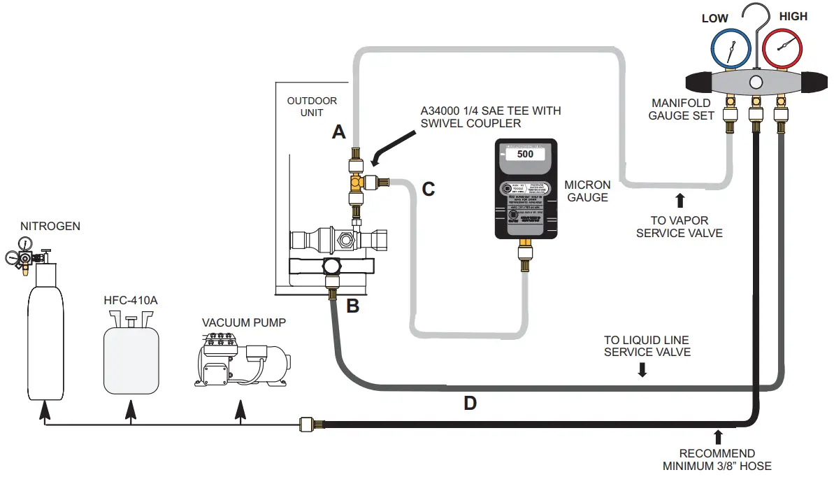 EVACUATE THE SYSTEM
A.Open both manifold valves and start the vacuum pump.
B. Evacuate the line set and indoor unit to an absolute pressure of 23,000 microns (29.01 inches of mercury).
NOTE — During the early stages of evacuation, it is desirable to close the manifold gauge valve at least once. A rapid rise in pressure indicates a relatively large leak. If this occurs, repeat the leak testing procedure.
NOTE — The term absolute pressure means the total actual pressure within a given volume or system, above the absolute zero of pressure. The absolute pressure in a vacuum is equal to atmospheric pressure minus vacuum pressure.
C. When the absolute pressure reaches 23,000 microns (29.01 inches of mercury), perform the following:
- Close manifold gauge valves
- Close valve on the vacuum pump
- Turn off the vacuum pump
- Disconnect manifold gauge center port hose from the vacuum pump
- Attach manifold center port hose to a dry nitrogen cylinder with a pressure regulator set to 150 psi (1034 kPa) and purge the hose.
- Open manifold gauge valves to break the vacuum in the line set and indoor unit.
- Close manifold gauge valves.
D. Shut off the dry nitrogen cylinder and remove the manifold gauge hose from the cylinder. Open the manifold gauge valves to release the dry nitrogen from the line set and indoor unit.
E. Reconnect the manifold gauge to the vacuum pump, turn the pump on, and continue to evacuate the line set and indoor unit until the absolute pressure does not rise above 500 microns (29.9 inches of mercury) within a 20-minute period after shutting off the vacuum pump and closing the manifold gauge valves.
F. When the absolute pressure requirement above has been met, disconnect the manifold hose from the vacuum pump and connect it to an upright cylinder of HFC-410A refrigerant. Open the manifold gauge valve 1 to 2 psig in order to release the vacuum in the line set and indoor unit.
G. Perform the following: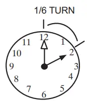
- Close manifold gauge valves.
- Shut off the HFC-410A cylinder.
- Reinstall service valve cores by removing manifold hose from service valve. Quickly install cores with core tool while maintaining positive system pressure.
- Replace stem caps and secure finger tight, then tighten an additional one-sixth (1/6) of a turn as illustrated
FIGURE 13. Evacuating the System
![]() IMPORTANT
IMPORTANT
Use a thermocouple or thermistor electronic vacuum gauge that is calibrated in microns. Use an instrument capable of accurately measuring down to 50 microns.![]() WARNING
WARNING
Possible equipment damage.
Avoid deep vacuum operation. Do not use compressors to evacuate a system. Extremely low vacuum can cause internal arcing and compressor failure. Damage caused by a deep vacuum operation will void the warranty. Evacuating the system of non-condensable is critical for the proper operation of the unit. Non-condensable are defined as any gas that will not condense under temperatures and pressures present during the operation of an air conditioning system.
Non-condensable and water suction combine with refrigerant to produce substances that corrode copper piping and compressor parts.
ELECTRICAL – Circuit Sizing and Wire Routing
In the U.S.A., wiring must conform with current local codes and the current National Electric Code (NEC). In Canada, wiring must conform with current local codes and the current Canadian Electrical Code (CEC).
Refer to the furnace or air handler installation instructions for additional wiring application diagrams and refer to the unit nameplate for minimum circuit ampacity and maximum
overcurrent protection size.
24VAC TRANSFORMER
Use the transformer provided with the furnace or air handler for low-voltage control power (24VAC – 40 VA minimum).
Thermostat Control and Low Voltage Control Wiring
EL18XCV Thermostat Control Options
The EL18XCV variable capacity units provide two thermostat control options to provide application and installation flexibility. iComfort S30 Communicating Thermostat
Control The EL18XCV variable capacity unit may be installed as a fully communicating iComfort system consisting of an iComfort S30 Ultra Smart Communicating Thermostat, an iComfort enabled indoor unit and the EL18XCV variable-capacity outdoor unit wired with (4) iComfort communication wires (R, I+, I- and C) connected to the EL18XCV
Outdoor Unitary Control.
The EL18XCV variable capacity unit when wired as a fully communicating iComfort system will take full advantage of the advanced diagnostics and control, Wi-Fi accessibility, and system operation parameters. Refer to the EL18XCV field wiring diagram for an iComfort S30 communicating thermostat.
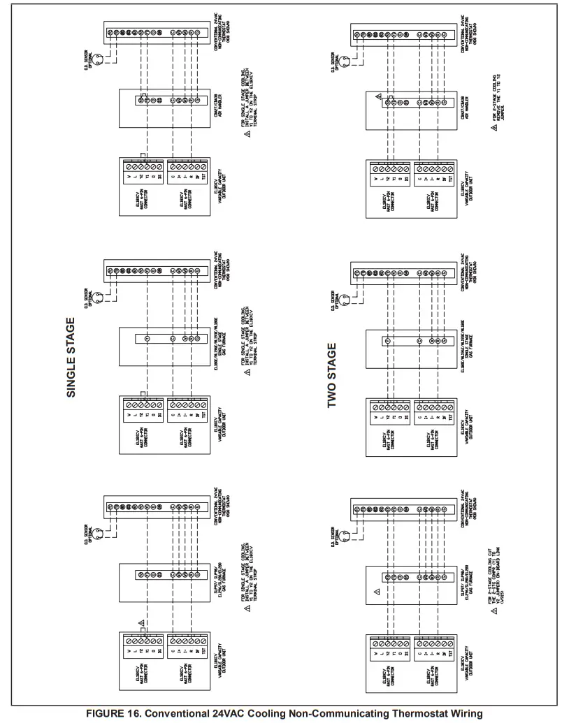
Conventional 24VAC Non-Communicating Thermostat Control
The EL18XCV variable capacity unit may be installed using a conventional 24VAC non-communicating two-stage cooling or single-stage cooling thermostat.
NOTE
– The conventional 24VAC non-communicating thermostat must have a compressor minimum time of three minutes to prevent compressor short cycling. The Lennox M30, ComfortSense 7500, ComfortSense 3000 and many other commercially available electronic thermostats provide this feature.
The EL18XCV unit will provide full variable capacity operation when installed with a conventional 24VAC non-communicating two-stage cooling or single-stage cooling thermostat.
The theEL18XCV outdoor control has advanced control algorithms using the EL18XCV suction pressure sensor to provide true variable capacity operation.
When utilizing a two-stage conventional 24VAC non-communicating thermostat, four wires are required to control the outdoor unit (R, C, Y1, and Y2). Refer to the EL18XCV field wiring diagram for a conventional 24VAC non-communicating 2-stage thermostat.
When utilizing a single-stage conventional 24VAC non-communicating thermostat, three wires are required to control the outdoor unit (R, C, and Y1) and Y1 is jumpered to
Y2 in the outdoor unit. Note that the published performance data is based upon the use of a two-stage thermostat. Refer to the EL18XCV field wiring diagram for a conventional 24VAC non-communicating single-stage thermostat.
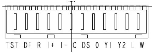
EL18XCV Low Voltage Control Wiring Connections
The EL18XCV variable capacity units are provided with (2) RAST 6-Pin connections in the installation instruction bag for connecting the field low voltage control wiring to the EL18XCV harnesses in the low voltage control makeup box. One RAST 6-pin connector is labeled with terminals TST, DF, R, I+, I-, and C. The second RAST 6-pin connector is labeled with terminals DS, O, Y1, Y2, L and W.![]() WARNING
WARNING![]() Electric Shock Hazard. Can cause injury or death. The unit must be properly grounded in accordance with national and local codes. Line voltage is present at all components when the unit is not in operation on units with single pole contactors. Disconnect all remote electric power supplies before opening the access panel. The unit may have multiple power supplies.
Electric Shock Hazard. Can cause injury or death. The unit must be properly grounded in accordance with national and local codes. Line voltage is present at all components when the unit is not in operation on units with single pole contactors. Disconnect all remote electric power supplies before opening the access panel. The unit may have multiple power supplies.![]() WARNING
WARNING
Fire Hazard. The use of aluminum wire with this product may result in a fire, causing property damage, severe injury, or death. Use copper wire only with this product.![]() WARNING
WARNING
Failure to use properly sized wiring and circuit breaker may result in property damage. Size wiring and circuit breaker(s) per Product Specifications bulletin (EHB) and unit rating plate.
EL18XCV Thermostat Control Options
| Thermostat Type | Indoor Unit Type | Qty. of Wires to EL18XCV | EL18XCV Terminal Strip Connections | Unit Operation | Field Wiring Diagram |
| iComfort S30 Communicating Thermostat | iComfort Communicating Gas Furnace or Air Handler | 4 | R, I+, I-, C | Fully Communicating Variable Capacity Operation Based Upon Thermostat Demand | Figure 15 |
| Conventional 24VAC 2-Stage Cooling Thermostat (non-communicating) | Any Furnace or Air Handler (non-communicating or communicating) | 4 | R, C, Y1, Y2 | Full Variable Capacity Operation Controlled by EL18XCV Unitary Control Using Suction Pressure | Figure 16 |
| Conventional 24VAC Single-Stage Cooling Thermostat (non-communicating) | Any Furnace or Air Handler (non- communicating or communicating) | 3 | R, C, Y1(Jumper Y1 to Y2) | Full Variable Capacity Operation Controlled by EL18XCV Unitary Control Using Suction Pressure | Figure 16 |
SIZE CIRCUIT AND INSTALL SERVICE DISCONNECT SWITCH
Refer to the unit nameplate for minimum circuit ampacity, and maximum fuse or circuit breaker (HACR per NEC). Install power wiring and properly sized disconnect switch.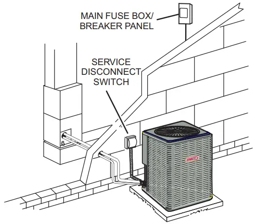
NOTE — Units are approved for use only with copper conductors. Ground unit at the disconnect switch or to earth ground.
INSTALL THERMOSTAT
Install room thermostat (ordered separately) on an inside wall approximately in the center of the conditioned area and 5 feet (1.5m) from the floor. It should not be installed on an outside wall or where it can be affected by sunlight or drafts.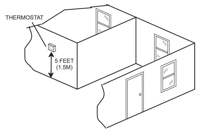
NOTE — 24VAC, Class II circuit connections are made in the control panel.
ROUTE CONTROL WIRES
iComfort Communicating Thermostat Wiring
The maximum length of wiring (18 gauge) for all connections on the bus is 1500 feet (457 meters). Wires should be color-coded, with a temperature rating of 95ºF (35ºC) minimum, and solid-core (Class II Rated Wiring). All low voltage wiring must enter the unit through a field-provided field-installed grommet installed in the electrical inlet.
Conventional 24VAC Non-Communicating Thermostat Wiring
WIRE RUN LENGTH…………………………….AWG# INSULATION TYPE
LESS THAN 100′ (30 METERS)……………….. 18 TEMPERATURE RATING
MORE THAN 100′ (30 METERS)……………………. 16 35ºC MINIMUM.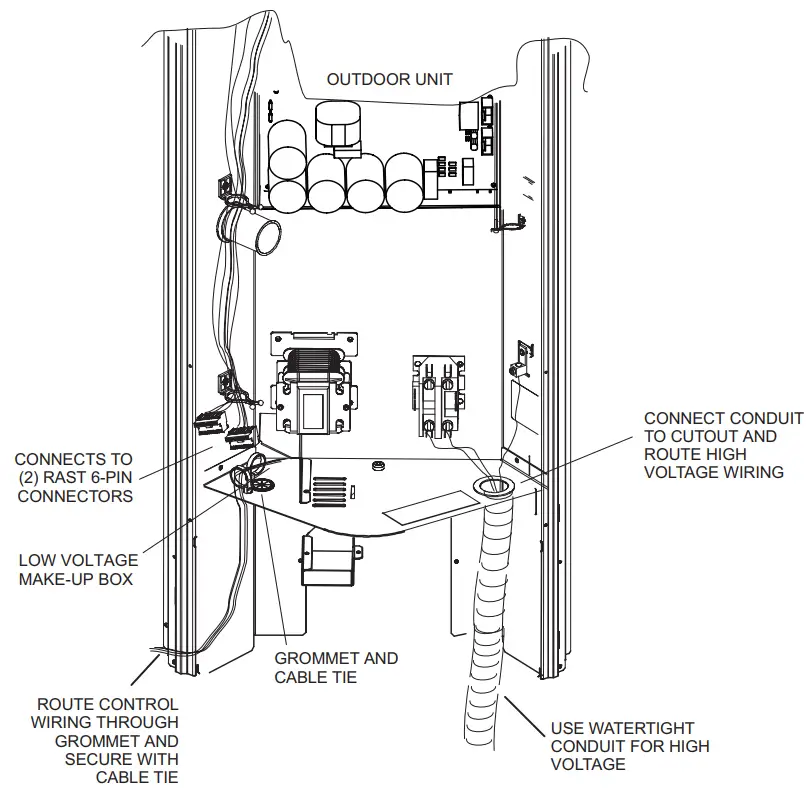
ROUTE HIGH VOLTAGE AND GROUND WIRES
Any excess high voltage field wiring should be trimmed and secured away from any low voltage field wiring. To facilitate a conduit, a cutout is located on the bottom of the control box. Connect conduit to the control box using a proper conduit fitting.
Connect the 208/230 high voltage power supply from the disconnect to the EL18XCV contactor as shown. Connect the ground wire from the power supply to the unit ground lug connection.
FIGURE 14. Typical Control Wiring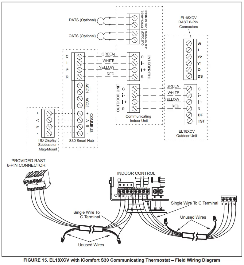
Outdoor Unitary Control – Jumpers and Terminals 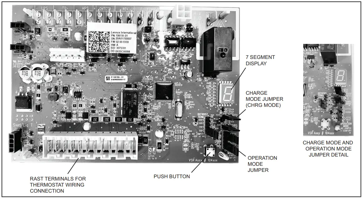
Outdoor Control 7 Segment Display and Push Button
Information concerning the outdoor control 7-segment display and push button operations are available on the unit access panel. Alarms Alarm information is provided on the unit access panel.
Charge Mode Jumper
To initiate the EL18XCV Charge Mode function, install the jumper across the two Charge Mode Pins (CHRG MODE) on the outdoor control. The Charge Mode can be used
when charging the system with refrigerant, checking the refrigerant charge, pumping down the system, and performing other service procedures that require outdoor unit operation at 100% capacity.
EL18XCV Charge Mode Operation with an S30 iComfort Communicating Thermostat
Installing a jumper on the Charge Mode Pins will initiate compressor operation and outdoor fan motor at 100% capacity and will provide a signal to the indoor unit to initiate indoor blower operation at the maximum cooling air volume. To exit the charge mode, remove the Charge Mode Jumper. The Charge Mode has a maximum time of 60 minutes and will automatically exit the charge mode after 60 minutes is the charge mode jumper is left in place.
EL18XCV Charge Mode Operation with a Conventional 24VAC Non-Communicating
Thermostat On applications with a conventional 24VAC non-communicating thermostat, the charge mode jumper must be installed on the Charge Mode Pins after providing a Y1 cooling demand to the EL18XCV to initiate the Charge Mode. A cooling blower demand must also be provided to initiate blower operation on the cooling speed on the indoor unit. The compressor and outdoor fan motor will operate at 100% capacity. To exit the charging mode, remove the Charge Mode Jumper and remove the Y1 Cooling demand and indoor blower demand. The Charge Mode has a maximum time of 60 minutes and will automatically exit the charge mode after 60 minutes is the charge mode jumper is left in place.
Operation Mode Jumper
The Operation Mode Jumper is only used on applications installed with a conventional 24VAC Non-communicating thermostat. In applications with a conventional 24VAC non-communicating thermostat, the compressor capacity is controlled to maintain the target suction pressure setpoint.
The Operation Mode Jumper has three selectable cooling modes. The three modes are Efficiency (Jumper installed on Pins 1 & 2), Normal Mode (Jumper installed on Pins 2 & 3) and Comfort Mode (Jumper Removed). The factory default position is the Efficiency Mode. The Efficiency mode has a variable suction pressure setpoint that will vary with the outdoor temperature; as the outdoor temperature increases the suction pressure setpoint will decrease. When the Operation Mode jumper is installed in the “Normal Mode” the suction pressure setpoint is 135 PSIG.
When the Operation Mode jumper is installed in the “Comfort Mode” the suction pressure setpoint is 125 PSIG. Unit Operation EL18XCV Unit Operation with a S30 iComfort Communicating Thermostat When the EL18XCV unit is installed with an S30 iComfort Communicating Thermostat and comfort-enabled indoor unit, the unit capacity will be controlled in the variable capacity mode throughout the range of capacity from minimum capacity to maximum capacity based upon thermostat demand. The indoor air volume will be controlled to match cooling capacity throughout the capacity range. EL18XCV Unit Operation with a Conventional 24VAC Non-Communicating 2-Stage Thermostat When the EL18XCV unit is installed with a conventional 24VAC non-communicating 2-stage thermostat, a Y1 first stage cooling demand will initiate cooling operation, and first stage indoor blower operation. The compressor will be controlled in the variable capacity mode by varying the compressor capacity to obtain the target suction pressure set point. The Y2 second stage cooling demand will initiate the second stage blower operation. Increased air volume will increase the load on the indoor coil and increase the suction pressure. The EL18XCV compressor capacity will continue to be controlled based on the suction pressure.
The unit capacity will be controlled in the variable capacity mode throughout the range of capacity from minimum capacity to maximum capacity. If the Y2 demand remains after 20 minutes, the EL18XCV control will begin to ramp up the compressor capacity until maximum capacity is achieved. The EL18XCV unit will cycle off once the thermostat demand is satisfied.
EL18XCV Unit Operation with a Conventional 24VAC Non-Communicating Single-Stage Thermostat
When the EL18XCV unit is installed with a conventional 24VAC non-communicating single-stage thermostat, a Y1 first stage cooling demand will initiate cooling operation and cooling indoor blower operation. In single-stage thermostat applications, a jumper must be installed between Y1 and Y2 on the EL18XCV outdoor control. The compressor will be controlled in the variable capacity mode by varying the compressor capacity to obtain the target suction pressure set point. If the cooling demand remains after 20 minutes, the EL18XCV control will begin to ramp up the compressor capacity until maximum capacity is achieved. The EL18XCV unit will cycle off once the thermostat demand is satisfied.
TABLE 6
| Outdoor Control Terminal Designations and Input /Outputs (see figure 15 for terminal locations) | ||||
| Designator | Description | Input | Output | Common |
| O | Unused on EL18XCV, for heat pump applications only | N/A | Switched 24VAC nominal | N/A |
| REV | Unused on EL18XCV, for heat pump applications only | N/A | N/A | 24VAC common |
| LPS | Low-pressure switch (not used on EL18XCV) | N/A | 5ma @ 18VAC | N/A |
| LPS | Low-pressure switch sensing connection (not used on EL18XCV) | 5ma @ 18VAC | N/A | N/A |
| HPS | High-pressure switch | N/A | 24VAC nominal | N/A |
| HPS | High-pressure switch sensing connection | 24VAC nominal | N/A | N/A |
| TP | Top cap thermostat switch (in series with the HPS) | N/A | 24VAC nominal | N/A |
| TP | Top cap thermostat switch sensing connection | 24VAC nominal | N/A | N/A |
| Contact | Control (inverter power) contactor switched output (in series with the HPS and TC) | N/A | Switched 24VAC nominal | N/A |
| Contact | Contactor common | N/A | 24VAC common | |
| FPWM | PWM fan output | N/A | 10-97% duty cycle, 19-23 VDC peak | |
| C | PWM fan common connection | N/A | N/A | Fan PWM common |
| P10 (PSC Fan 1/4ʺ QC) | 1/4ʺ QC terminals – Switched output for PSC outdoor fan control | N/A | Switched 230VAC Nominal | N/A |
| RAST Connector Terminal Designations | ||||
| W | Unused on ELXCV, for heat pump applications only | N/A | 24VAC nominal | N/A |
| L | 24VAC input to initiate load shed | 24VAC nominal from load shedN.O. contacts (close to initiating load shed) | N/A | N/A |
| Y2 | Y2 second stage cooling input when a conventional 24VAC non-communicating thermostat is used. Must be jumpered to Y1 if a single-stage cooling thermostat is used | 24VAC nominal from the thermostat | N/A | N/A |
| Y1 | Y1 first stage cooling input when a conventional 24VAC non-communicating thermostat is used | 24VAC nominal from the thermostat | N/A | N/A |
| O | Unused on EL18XCV, for heat pump applications only | 24VAC nominal from the thermostat | N/A | N/A |
| DS | Dehumidification input – not used | N/A | N/A | N/A |
| C | 24VAC nominal power return | N/A | N/A | 24VAC common |
| I- | Low data line | Data | Data | N/A |
| I+ | High data line | Data | Data | N/A |
| R | 24VAC nominal power input | 24VAC nominal board main power input | N/A | N/A |
| DF | OEM test | N/A | N/A | N/A |
| TEST | OEM test pin | 24VAC nominal | N/A | N/A |
| Outdoor Control Terminal Designations and Inputs / Outputs | ||||||||
| WARNING – Electric Shock Hazard. Can cause injury or death. Unit must be grounded in accordance with national and local codes. The 4 pins in P6 have the potential of transferring up to 250 volts to the unit cabinet ground. | ||||||||
| Designator | Description | Input | Output | Common | ||||
| P6 – Pin 1 | Tx | Transmit data to inverter, connects to Rx ofinverter | Outdoor control communication transmits pin | – Pin 1 to pin 2 should read 4.5 to 5.55 VDC when not communicating – Pin 3 to pin 2 should read 4.5 to 5.55 VDC when not communicating – Pin 4 to pin 2 should read 4.5 to 5.5 VDC NOTE – Communication signals switch off and on rapidly. This may cause volt meter readings to fluctuate. This is normal. Com- munication signals will switch between this 5V and common (Pin 2). | ||||
| P6 – Pin2 | Inverter Common | Inverter common note – This is a signal reference point and not earth ground. | Inverter common | |||||
| P6 – Pin 3 | Rx | Receive data from the inverter Connects to Tx of inverter | Outdoor control communication receive pin | |||||
| P6 – Pin 4 | Inv 5V | Inverter 5VDC volts | Inverter 5VDC volts | |||||
| DIS | Discharge Line temperature sensor – not used (10K ohm resistor installed) | N/A | N/A | N/A | ||||
| DIS | Discharge Line temperature sensor – not used (10K ohm resistor installed) | N/A | N/A | N/A | ||||
| AMB | Outdoor ambient temperature sensor supply | N/A | N/A | N/A | ||||
| AMB | Outdoor ambient temperature sensor return | N/A | N/A | N/A | ||||
| COIL | Outdoor coil temperature sensor – not used (10K ohm resistor installed) | N/A | N/A | N/A | ||||
| COIL | Outdoor coil temperature sensor – not used (10K ohm resistor installed) | N/A | N/A | N/A | ||||
| CHRG MODE | Charge Mode function. Can be used when charging, checking charge, pump down or check- ing unit operation. Unit will run at 100% capacity. Conventional 24VAC thermostat 1. Install the Charge Mode jumper (before the Y1 demand) 2. Provide a Y1 demand to the L18XCV 3. A blower demand must be provided to the in-door unit for 100% of the cooling air volume. 4. Remove the charge mode jumper to end the charge mode S30 Communicating Thermostat 1. Install the Charge Mode jumper 2. Unit will start and run at 100% capacity and communicate to the indoor unit to bring on the blower at 100% of the cooling air volume. 4. Remove the charge mode jumper to end the charge mode NOTE – If the charge mode jumper is in the ON position during power-up, it is ignored. NOTE – If the charge mode is left in place, it will be ignored after 60 minutes. | 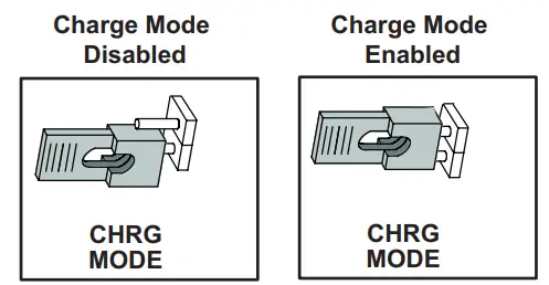 | ||||||
| Suction Pressure Out | Pressure transducer Supply Voltage Pin 1of 3 | 5 VDC | ||
| Suction Pressure In | Pressure transducer output voltage Pin 2 of 3 | 0-4.5 VDC | ||
| Suction Pressure GND | Pressure transducer GND Pin 3 of 3 | VDC Com | ||
| Liquid Pressure Out | Pressure transducer Supply Voltage Pin 1 of 3 – Not used on EL18XCV Air Conditioner | 5 VDC | ||
| Liquid Pressure In | Pressure transducer Supply Voltage Pin 2 of 3 – Not used on EL18XCV Air Conditioner | 0-4.5 VDC | ||
| Liquid Pressure GND | Pressure transducer GND Pin 3 of 3 – Not used on EL18XCV Air Conditioner | VDC Com | ||
| SUCT1 | Suction Line Temperature Sensor Supply -Pin 1 of 4 | 0-4.5 VDC | ||
| SUCT2 | Suction Line Temperature Sensor Supply -Pin 2 of 4 | |||
| LIQ1 | Liquid Line Temperature Sensor Supply -Pin 3 of 4 | 0-4.5 VDC | ||
| LIQ2 | Liquid Line Temperature Sensor Supply -Pin 4 of 4 |
Servicing Units Delivered Void of Charge
If the outdoor unit is void of refrigerant, clean the system using the procedure described below.
- – Leak test the system using the procedure outlined on page 22.
- – Evacuate the system using the procedure outlined on page
- – Use nitrogen to break the vacuum and install a new filter drier in the system.
- – Evacuate the system again using the procedure outlined on page
- – Weigh refrigerant using the procedure outlined in figure 56.
- – Monitor the system to determine the amount of moisture remaining in the oil. It may be necessary to replace the filter drier several times to achieve the required dryness level. If system dryness is not verified, the compressor will fail in the future.
Unit Start-Up
|
| If the unit is equipped with a crankcase heater, it should be energized 24 hours before unit start-up to prevent compressor damage as a result of slugging. |
- – Rotate the fan to check for
- – Inspect all factory- and field-installed wiring for loose connections.
- – After evacuation is complete, open both the liquid and vapor line service valves to release the refrigerant charge contained in the outdoor unit into the
- – Replace the stem caps and tighten them to the value listed in table 1.
- – Check the voltage supply at the disconnect switch. The voltage must be within the range listed on the unit If not, do not start the equipment until you have consulted with the power company and the voltage condition has been corrected.
- – Set the thermostat for a cooling demand. Turn on power to the indoor unit and close the outdoor unit disconnect switch to start the
- – Recheck voltage while the unit is Power must be within the range shown on the nameplate.
- – Check the system for sufficient refrigerant by using the procedures listed in the System Refrigerant section on page
System Operation and Service
7-SEGMENT ALERT AND SYSTEM STATUS CODES
Alert codes are displayed using the 7-segment display located on the outdoor control. NOTE – System fault and lockout codes take precedence over system status codes (cooling, heating operating percentages or defrost/dehumidification). The 7-segment will display an abnormal condition (error code) when detected in the system. A
list of the codes are shown in table 6.
Resetting Alert Codes
Alert codes can be reset manually or automatically:
1 – Manual Reset
A manual reset can be achieved by one of the following methods:
• Disconnecting R wire from the outdoor control R terminal.
• Turning the indoor unit off and back on again
After power up, all currently displayed codes are cleared.
2 – Automatic Reset
After an alert is detected, the outdoor control continues to monitor the unit’s system and compressor operations. When/if conditions return to normal, the alert code is turned off automatically.
NOTE – Error codes can be recalled by following information shown in the table on page 37.
| TABLE 7. Outdoor Control 7-Segment Display Alert Codes and Inverter LED Flash Codes NOTE – System fault and lockout codes take precedence over system status codes (cooling, heating operating percentages or defrost/dehumidification). Only the latest active fault or lockout codes are displayed (if present). If no fault or lockout codes are active, then system status codes are displayed. Alert codes are also displayed on the iComfort® S30 thermostat. | ||||||
| Alert Codes | Inverter Code | Inverter LED Flash Code (number of flashes) | Priority | Alarm Description | Possible Causes and Clearing Alarm | |
| Red LED | Green LED | |||||
| N/A | N/A | ON | OFF | N/A | EL18XCVS024, 036, EL18XCV-024, -036 only: Indicates inverter is operating normally. | |
| N/A | N/A | ON | ON | N/A | EL18XCVS048, 060, EL18XCV-048, -060 only: Indicates inverter is operating normally. | |
| N/A | N/A | OFF | OFF | N/A | Indicates inverter is NOT energized. | |
| E105 | N/A | N/A | N/A | Moderate | The outdoor control has lost communication with either the thermostat or the indoor unit. | The equipment is unable to communicate. Indicates numerous message errors. In most cases, errors are related to electrical noise. Make sure high voltage power is separated from RSBus. Check for miswired and/or lose connections between the stat, indoor unit and outdoor unit. Check for a high voltage source of noise close to the system. Fault clears after communication is restored. |
| E120 | N/A | N/A | N/A | Moderate | There is a delay in the outdoor unit responding to the system. | Typically, this alarm/code does not cause any issues and clears on its own. The alarm/code is usually caused by a delay in the outdoor unit responding to the thermostat. Check all wiring connections. Cleared after unresponsive device responds to any inquiry. |
| E124 | N/A | N/A | N/A | Critical | The iComfort S30 thermostat has lost communication with the outdoor unit for more than 3 minutes. | Equipment lost communication with the thermostat. Check the wiring connections and resistance, then cycle the system power. This alarm stops all associated HVAC operations and waits for a signal from the non-communicating unit. The alarm / fault clears after communication is re-established. |
| E125 | N/A | N/A | N/A | Critical | There is a hardware problem with the outdoor control. | There is a control hardware problem. Replace the outdoor control if the problem prevents operation and is persistent. The alarm/fault is cleared 300 seconds after the fault recovers. |
| E131 | N/A | N/A | N/A | Critical | The outdoor unit control parameters are corrupted. | Reconfigure the system. Replace the control if heating or cooling is not available. |
| E132 | N/A | N/A | N/A | Critical | Internal software error. | Replace outdoor control. |
| E18 | N/A | N/A | N/A | Critical | The outdoor unit ambient temperature sensor has malfunctioned. As a result, the outdoor unit control will not perform low ambient cooling. | Valid temperature reading is lost during normal operation and after outdoor control recognized sensors. Compare outdoor sensor resistance to temperature/ resistance charts in unit installation instructions. Replace sensor pack if necessary. At the beginning of (any) configuration, furnace or air handler control detects the presence of the sensor(s). If detected (reading in range), an appropriate feature is shown in the iComfort S30 thermostatAbout screen. The alarm/fault clears upon configuration, or when normal values are sensed. |
| E181 | N/A | N/A | N/A | Moderate | Suction pressure transducer fault. | A suction pressure transducer is out of range. The signal should be between 0.5 VDC and 4.5 VDC between blue and black. The error code will be cleared when the proper signal is provided. |
| E182 | N/A | N/A | N/A | Moderate | The suction temperature sensor has malfunctioned. | Check the temperature sensor in the applicable installation and service procedure. Nominal resistance is 10K Ohms at 77F. |
| E345 | N/A | N/A | N/A | Critical | Heat Pump or Air Conditioner Alert Code – The “O” relay on the outdoor board has failed. | Either the pilot relay contacts did not close, the relay coil did not energize the circuit which confirms this operational sequence is not sensing properly. |
| TABLE 7. Outdoor Control 7-Segment Display Alert Codes and Inverter LED Flash Codes NOTE – System fault and lockout codes take precedence over system status codes (cooling, heating operating percentages or defrost/dehumidification). Only the latest active fault or lockout codes are displayed (if present). If no fault or lockout codes are active, then system status codes are displayed. Alert codes are also displayed on the iComfort® S30 thermostat. | ||||||
| Alert Codes | Inverter Code | Inverter LED Flash Code (number of flashes) | Priority | Alarm Description | Possible Causes and Clearing Alarm | |
| Red LED | Green LED | |||||
| E409 | N/A | N/A | N/A | Moderate | Outdoor control secondary voltage is 18VAC or less. | Secondary voltage is below 18VAC. After 10 minutes, operation is discontinued. Check the indoor line voltage and transformer output voltage. The alarm clears after the voltage is higher than 20VAC for 2 seconds or after a power reset. |
| E410 | N/A | N/A | N/A | Moderate | The outdoor unit cycled off due to low suction pressure. | Unit pressure is below the lower limit. The system is shut down. The suction pressure transducer emulates a low pressure switch, the unit does not have a low pressure switch. The cut-out is set at 40 PSIG and the cut-in set at 90 PSIG. Confirm that the system is properly charged with refrigerant. Check TXV, indoor unit blower motor, dirty filters or clogged refrigerant filter. Confirm that the evaporator coil is clean. The alarm clears after the pressure rises above 90 PSIG. |
| E411 | N/A | N/A | N/A | Critical | The low-pressure fault has occurred 5 times within one hour. As a result, the outdoor unit is locked out. | The low-pressure fault error count reached 5 strikes. The low-pressure cut-out is at 40PSIG and resets at 90PSIG. Confirm that the system is properly charged with refrigerant. Check for clogged TXV, blockage to the indoor unit blower motor, dirty filters or clogged refrigerant filter. Confirm that the evaporator coil is clean. The alarm clears after a power reset. |
| E412 | N/A | N/A | N/A | Moderate | The outdoor unit’s high-pressure switch has opened. | Unit pressure is above the upper limit. The system is shut down. The high-pressure switch opens at 590PSIG and closes at 418PSIG. Confirm that the system is properly charged with refrigerant. Check for clogged TXV, blockage to the indoor unit blower motor, and clogged refrigerant filter. Confirm that the outdoor unit is clean. The alarm clears after the pressure switch closes or a power reset. For heating, indoor CFM may be set too low. For the zoning system, zone CFM may be set too low. |
| E413 | N/A | N/A | N/A | Critical | The high-pressure switch has opened 5 times within one hour. As a result, the outdoor unit is locked out. | Open high-pressure switch error count reached 5 strikes. The system is shut down. The high-pressure switch for HFC410A opens at 590PSIG and closes at 418PSIG. Confirm that the system is properly charged with refrigerant. Check condenser fan motor, for clogged TXV, for the blockage to the indoor unit blower motor, for stuck reversing valve or clogged refrigerant filter. Confirm that the outdoor unit is clean. The alarm clears after a power reset. For heating, indoor CFM may be set too low. For the zoning system, zone CFM may be set too low. |
| E416 | N/A | N/A | N/A | Moderate / Critical | The outdoor coil sensor has malfunctioned. | EL18XCV has a fixed 10K ohm resistor installed on the harness connector between pins 5 & 6. Check connections on pins 5 & 6 and check for resistance of 10K ohms. Error code will occur on open or shorted circuit |
| E422 | N/A | N/A | N/A | Moderate | Compressor top cap switch exceeding the thermal limit. | The top of the compressor is hot. A refrigerant charge may be low, or low mass flow of refrigerant. Check TXV, clogged filter drier, condenser fan motor, indoor blower motor, and confirm indoor coil is clean. |
| E423 | 40 | 4 flashes | OFF | Moderate / Critical | The inverter has detected a circuit problem. | Control locks out after 10 strikes within an hour. To clear, disconnect power to the indoor unit (24VAC power source to the outdoor control) which will power off the outdoor control and will open the outdoor unit contactor, which interrupts power to the inverter and then re-apply power. |
| E424 | N/A | N/A | N/A | Moderate | The liquid line temperature sensor has malfunctioned. | Check connections between pins 3 and 4 of the four-pin liquid/ suction temperature plug on the bottom left corner of the control. Check resistance of the resistor. Nominal 10K Ohms at 77F. Error code occurs if the sensor is open or shorted. |
| E425 | N/A | N/A | N/A | Minor | Outdoor control has increased the minimum compressor speed to allow for proper oil return due to low ambient temperature. NOTE- Minimum speed adjustments begin at 45°F and increase to 100% minimum at 17°F. | The outdoor ambient temperature is below the system limit. Control attempts to run at the lowest allowed compressor speed to allow for proper oil return. Automatically clear when the outdoor ambient temperature rises above the limit for more than 5 minutes. |
| E426 | N/A | N/A | N/A | Critical | Excessive inverter alarms | After ten faults within one hour, control is locked out, indicating poor system operation. Review history of alarms to resolve system setup. Check condenser fan motor, TXV, indoor unit blower motor, over-charge, undercharge, or clogged refrigerant filter. To clear, disconnect power to the indoor unit (24VAC power source to the outdoor control) which will power off the outdoor control and will open the outdoor unit contactor, which interrupts power to the inverter and then re-apply power. Inverter alarms 12 to 14 and 53 do not count toward this lock-out condition. |
| TABLE 7. Outdoor Control 7-Segment Display Alert Codes and Inverter LED Flash Codes NOTE – System fault and lockout codes take precedence over system status codes (cooling, heating operating percentages or defrost/dehumidification). Only the latest active fault or lockout codes are displayed (if present). If no fault or lockout codes are active, then system status codes are displayed. Alert codes are also displayed on the iComfort® S30 thermostat. | ||||||
| Alert Codes | Inverter Code | Inverter LED Flash Code (number of flashes) | Priority | Alarm Description | Possible Causes and Clearing Alarm | |
| Red LED | Green LED | |||||
| E427 | 21 | 2 flashes | 1 flash | Moderate/ Critical | The inverter has detected a DC peak fault condition. If condition (55A or higher) is detected, outdoor unit compressor and fan stop. Anti-short cycle is initiated. If peak current (55A or higher) occurs 10 times within an hour, system is locked out. Indicates high pressure, condenser fan failure, locked compressor rotor or overcharge. To clear, disconnect power to the indoor unit (24VAC power source to the outdoor control) which will power off the outdoor control and will open the outdoor unit contactor, which interrupts power to the inverter and then re-apply power.. | |
| E428 | 22 | 2 flashes | 2 flashes | Moderate/ Critical | The inverter has detected a high main input current condition. | If the condition is detected, is detected, outdoor unit compressor and fan stop. Antishort cycle is initiated. If the condition occurs 5 times within an hour, the system is locked out. Indicates high pressure, condenser fan failure or overcharge. |
| E429 | 23 | 2 flashes | 3 flashes | Moderate/ Critical | On a call for compressor operation, if DC link power in the inverter does not rise above 180 VDC for 2 and 3-ton models, 250 VDC for 4 and 5-ton models, within 30 seconds, the control will display a moderate code. If the condition is detected, the outdoor unit will stop (Compressor and fan). Antishort cycles is initiated. If the condition occurs 10 times within a 60-minute rolling time period, the system will lock out and display a critical code. |
Issues: |
| E430 | 26 | 2 flashes | 6 flashes | Moderate/ Critical | Compressor start failure | If the condition is detected, the outdoor unit compressor and fan stop. Antishort cycle is initiated. If the condition occurs 10 times within an hour, the system is locked out. Indicates poor connection at compressor harness, improper winding resistance, locked compressor rotor, or flooded compressor. To clear, disconnect power to the indoor unit (24VAC power source to the outdoor control) which will power off the outdoor control and will open the outdoor unit contactor, which interrupts power to the inverter and then re-apply power. |
| E431 | 27 | 2 flashes | 7 flashes | Moderate/ Critical | The error occurs when PFC detects an over-current condition of 100A, the control will display a moderate code. If the condition is detected, the outdoor unit will stop (Compressor and fan). Anti- short cycle is initiated. The inverter is unavailable to communicate with the outdoor control for 3 minutes. If the condition occurs 10 times within a 60-minute rolling time period, the system will lock out and display a critical code. | Issues: (1) Indicates power interruption, brownout, poor electrical connection or loose inverter input wire. 2) System testing was set up and code was generated when the reversing valve is de-energized coming out of defrosting (code appears with or without 30 compressor delay). Corrective Actions: (1) Check for proper main power to the outdoor unit and for any loose electrical connections. (2) To clear, disconnect power to the indoor unit (24VAC power source to the outdoor control) which will power off the outdoor control and will open the outdoor unit contactor, which interrupts power to the inverter and then re-apply power. |
| E432 | 28 | 2 flashes | 8 flashes | Moderate/ Critical | The inverter has detected a DC link high voltage condition | The error occurs when the DC link capacitor voltage is greater than 480VDC. If the condition is detected, the outdoor unit compressor and fan stop. Anti-short cycle is initiated. If the condition occurs 10 times within an hour, the system is locked out. System stops. To clear, disconnect power to the indoor unit (24VAC power source to the outdoor control) which will power off the outdoor control and will open the outdoor unit contactor, which interrupts power to the inverter and then re-apply power. |
| E433 | 29 | 2 flashes | 9 flashes | Moderate/ Critical | The inverter has detected a compressor over-current condition. | The error occurs when the compressor peak phase current is greater than 28A. Inverter issues code 14 first and slow down to try to reduce the current. If the current remains high, the outdoor unit compressor and fan stop. Anti-short cycle is initiated. If the condition occurs five times within an hour, the system is locked out. To clear, disconnect power to the indoor unit (24VAC power source to the outdoor control) which will power off the outdoor control and will open the outdoor unit contactor, which interrupts power to the inverter and then re-apply power. |
| TABLE 7. Outdoor Control 7-Segment Display Alert Codes and Inverter LED Flash Codes NOTE – System fault and lockout codes take precedence over system status codes (cooling, heating operating percentages or defrost/dehumidification). Only the latest active fault or lockout codes are displayed (if present). If no fault or lockout codes are active, then system status codes are displayed. Alert codes are also displayed on the iComfort® S30 thermostat. | ||||||
| Alert Codes | Inverter Code | Inverter LED Flash Code (number of flashes) | Priority | Alarm Description | Possible Causes and Clearing Alarm | |
| Red LED | Green LED | |||||
| E434 | 53 | 5 flashes | 3 flashes | Moderate/ Critical | Outdoor control has lost communications with the inverter for greater than 3 minutes. Outdoor unit will stop all compressor demand. Outdoor control will attempt to establish communication multiple times and will automatically clear when the error clears. Unit will lock out after 60 minutes if communication is not established and will display a critical error code. | Issues: (1) Outdoor disconnect is off or outdoor power is off, when indoor power is on (source for 24VAC) (2) Loose electrical power connections (3) interruption of main power to the inverter (4) Generator powers indoor unit, but not the outdoor unit. Corrective Actions: (1) To reset, cycle the indoor power off (source of 24VAC to outdoor unit) and back on. This will de-energize outdoor control and inverter by cycling the contactor. 2) Make sure the disconnect is on (3) check electrical power supply connections (4) Check for proper main 230V power supply |
| E435 | 60 | 6 flashes | OFF | Moderate/ Critical | Inverter internal error | When this error occurs, the outdoor control cycles power to the inverter by opening the contactor for two minutes. Check that the EEPROM is properly seated. After power is cycled to the inverter 3 times, the outdoor unit is locked out. If problem persists, replace the inverter. |
| E436 | 62 | 6 flashes | 2 flashes | Moderate / Critical | Inverter heat sink temperature exceeded limit. Occurs when the heat sink temperature exceeds the inverter limit. Inverter issues code 13 first, then slows down to allow the heat sink to cool. If the temperature remains high, the outdoor unit stops (compressor and fan). Anti-short cycle is initiated. If the condition occurs 5 times within an hour, the system is locked out. To clear, disconnect power to the indoor unit (24VAC power source to the outdoor control) which will power off the outdoor control and will open the outdoor unit contactor, which interrupts power to the inverter and then re-apply power. | Issue: This error may occur if the outdoor fan fails to operate or the inverter heat sink is obstructed with debris. Feedback from supplier tear down of inverter indicates that the screws that hold the inverter to the inverter board were loose causing poor contact between these two components. Corrective Action: Tighten screws that hold the heat sink to the inverter control board. NOTE: Wait five minutes to allow capacitor to discharge before checking screws. |
| E437 | 65 | 6 flashes | 5 flashes | Moderate / Critical |
Heat sink temperature sensor fault has occurred (temperature less than 4ºF or greater than 264ºF after 10 minutes of operation). | Occurs when the temperature sensor detects a temperature less than 0.4ºF or greater than 264ºF after 10 minutes of operation. If the condition is detected, the outdoor unit will stop (compressor and fan). Anti-short cycle is initiated. If the condition occurs 5 times within an hour, the system will lock out. To clear, disconnect power to the indoor unit (24VAC power source to the outdoor control) which will power off the outdoor control and will open the outdoor unit contactor, which interrupts power to the inverter and then re-apply power. If the problem persists, replace the inverter. |
| E438 | 73 | 7 flashes | 3 flashes | Moderate/ Critical | The inverter has detected a PFC over the current condition. This would be caused by a high load condition, high pressure, or outdoor fan failure. Outdoor control will display the code when the inverter has the error. After 3 minutes, the inverter will reset and the compressor will turn on again. If it happens 10 times within a 60 minute rolling time period, the OD control will lock out operation of the outdoor unit and display a critical code. | Issue: Possible issue is the system running at high pressures. Check for high-pressure trips or other alert codes in-room thermostat and outdoor control. To clear, disconnect power to the indoor unit (24VAC power source to the outdoor control) which will power off the outdoor control and will open the outdoor unit contactor, which interrupts power to the inverter and then re-apply power. |
| E439 | 12 | 1 flash | 2 flashes | Minor | Compressor slowdown due to high input current. | This error code is primarily for informational purposes as the inverter controls the compressor to operate within design parameters. Typically the inverter will make a minor speed reduction of 4 Hz (approximately a 5-6% speed reduction) for a brief period of time and to reduce the input current and will then resume normal operation. |
| TABLE 7. Outdoor Control 7-Segment Display Alert Codes and Inverter LED Flash Codes NOTE – System fault and lockout codes take precedence over system status codes (cooling, heating operating percentages or defrost/dehumidifi- cation). Only the latest active fault or lockout codes are displayed (if present). If no fault or lockout codes are active, then system status codes are displayed. Alert codes are also displayed on the iComfort® S30 thermostat. | ||||||
| Alert Codes | Inverter Code | Inverter LED Flash Code (number of flashes) | Priority | Alarm Description | Possible Causes and Clearing Alarm | |
| Red LED | Green LED | |||||
| E440 | 13 | 1 flash | 3 flashes | Minor | The heat sink temperature is approaching the limit. The compressor speed automatically slows to reduce heat sink temperature. The control sets indoor CFM and outdoor RPM to values according to demand percentage rather than the actual Hz. Alarm is automatically cleared. | This error code is primarily for informational purposes as the inverter controls the compressor speed to operate within design parameters. Typically the inverter will make a minor speed reduction of 4 Hz (approximately a 5-6% speed reduction) for a brief period of time and to reduce the heat sink temperature and will then resume normal operation. This may occur at high outdoor temperatures (above 110ºF) for brief periods of time (3 – 4 minutes) and is the normal and expected operation of the inverter controlling the compressor safely within design parameters. The inverter finned aluminum heat sink is located on the back side of the inverter in the condenser air stream. f alert code 440 occurs frequently, especially at lower outdoor temperatures, check the heat sink for debris that may reduce heat transfer or possible obstructions that may impact airflow across the heat sink. The inverter will begin to briefly reduce the compressor speed when the heat sink temperature rises above 185ºF and will allow the inverter to resume the requested compressor demand speed once the inverter heat sink reaches 176ºF. The heat sink temperature, compressor speed in Hertz and the Inverter Compressor Speed Reduction status (“On” or “Off ”) notification can be viewed under the outdoor unit Diagnostics section of the thermostat dealer control center on units installed with an S30 thermostat. |
| E441 | 14 | 1 flash | 4 flashes | Minor | Compressor slowdown due to high compressor current. The compressor current is approaching the limit. The compressor speed automatically slows. The control sets indoor CFM and outdoor RPM to values according to demand percentage rather than the actual Hz. Alarm is automatically cleared. | This error code is primarily for informational purposes as the inverter controls the compressor to operate within design parameters. Alert code 441 typically occurs at startup as the compressor as currently increases rapidly during startup. The inverter will reduce the compressor speed by 4 Hz and slow the compressor ramp up the speed to the requested compressor demand (capacity). This is the normal and expected operation of the inverter to control the compressor within design parameters. In most cases the alert code 441 does not require any additional service or diagnostic procedures. E441 may also occur if the system is operating at high pressures. |
| E442 | N/A | N/A | N/A | Critical | The top cap switch has opened five times within one hour. As a result, the outdoor unit is locked out. | When the compressor thermal protection sensor opens five times within one hour, the outdoor stops working. To clear, disconnect power to the indoor unit (24VAC power source to the outdoor control) which will power off the outdoor control and will open the outdoor unit contactor, which interrupts power to the inverter and then re-apply power. |
| E443 | N/A | N/A | N/A | Critical | Incorrect appliance unit size code selected. | Check for proper configuring of unit size codes for the outdoor unit in the configuration guide or in installation instructions. If replacing the inverter, verify inverter model matches the unit size. The alarm/ fault clears after the correct match is detected following a reset. Remove the thermostat from the system while applying power and reprogramming. |
| E600 | N/A | N/A | N/A | Minor | The compressor has been cycled OFF on utility load shedding. | Load shedding function: Provides a method for a local utility company to limit the maximum power level usage of the outdoor unit. The feature is activated by applying 24 volts AC power to the L and C terminals on the outdoor control. |
| E601 | N/A | N/A | N/A | Minor | The outdoor unit has been cycled OFF on low-temperature protection. | Low temperature protection: Outdoor unit will not operate when the outdoor temperature is at or below 4°F (20°C). If the unit is operating and the outdoor temperature drops below 4°F (20°C), the unit continues to operate until the room thermostat is satisfied or the outdoor temperature drops to 15°F (26°C). Outdoor unit ambient sensor provides temperature readings. |
POWER-UP / RESET:
FIRMWARE VERSION: During initial power-up or reset, the first item displayed is the outdoor control firmware version.
The example to the right shows firmware version 2.3.
UNIT TYPE: The next item displayed is the self-discovery unit type. AC = air conditioner and HP = heat pump. If the unit type cannot be determined, three bars appear.
UNIT NOMINAL CAPACITY: The next item to be displayed is the self-discovery unit nominal capacity. Valid capacities are 24 for 2-ton, 36 for 3-ton, 48 for 4-ton, and 60 for 5-ton units. If the unit type cannot be determined, three bars appear.
UNIT CODE: The next item to be displayed is the self-discovery unit code. (maybe a single character or two characters). If the unit code cannot be determined, three bars appear.
| UNIT CODE | UNIT TYPE, SIZE, AND MODEL |
| NOT PROGRAMMED | |
| 2-TON AIR CONDITIONER [ EL18XCVS024 EL18XCV-024 | |
| 3-TON AIR CONDITIONER [ EL18XCVS036 EL18XCV-036 | |
| 4-TON AIR CONDITIONER [ EL18XCVS048 EL18XCV-048 | |
| 5-TON AIR CONDITIONER [ EL18XCVS060 | |
| 5-TON AIR CONDITIONER [ EL18XCV-060 |
7-SEGMENT POWER-UP DISPLAY STRING
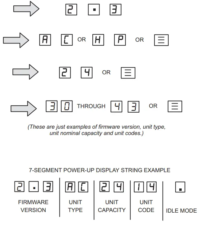 FIGURE 17. Outdoor Control 7-Segment Unit Status Displays
TABLE 8. Outdoor Control 7-Segment Unit Status Displays
| Description | Example of Display |
| Idle Mode: Decimal point flashes at 1 Hz. | Idle Mode: Decimal point flashes at 1 Hz (0.5 second on, 0.5 second off). Display OFF. |
| Soft Disable Mode: Top and bottom horizontal line and decimal point flash at 1 Hz. If indoor or outdoor control displays Soft Disable code: 1) Confirm proper wiring between all devices (thermostat, indoor and outdoor). 2) Cycle power to the control that is displaying the Soft Disable code. 3) Put the room thermostat through Setup. 4) Go to Setup/System Devices/Thermostat/Edit/push Reset. 5) Go to Setup/System Devices/Thermostat/Edit/push Reset All. If the room thermostat detects a new device or a device that is not communicating, it sends a Soft Disable. When this occurs, Alarm 10 is activated and the room thermostat sends a Soft Disable command to the offending device on the bus (outdoor control, IFC, AHC, EIM or Damper Control Module). | Soft Disable Mode: Top and bottom horizontal line and decimal point flash at 1 Hz (0.5 second on, 0.5 second off). The iComfort control in Soft Disable Mode is indicated by the following: • On AHC, IFC and outdoor controls, Soft Disable Mode is indicated by flashing double horizontal lines on the 7-segment display. • On the Damper Control Module and EIM, the green LED will blink 3 seconds on and 1 second off. |
| O.E.M. Test Mode | All segments flash at 2 Hz (unless the error is detected). NOTE – Control should be replaced. |
| Anti-Short-Cycle Delay | The middle line flashes at 1 Hz for 2 seconds, followed by a 2-second display of the number of minutes left on the timer (value is rounded up: 2 min. 1 sec. is displayed as 3). If activated, the anti-short cycle delay time remaining is displayed (default is 300 sec./5 min.). |
| Cooling Capacity: Shows cooling stage C1 or C2 operating if non-communicating. Shows cooling capacity percentage i.e. C70 operating if installed with an S30 communicating thermostat. The example to the right indicates a cooling demand of 50 percent. | Cooling compressor capacity (1 second on, 0.5 seconds off) followed by ambient temperature. Non-Communicating thermostat with second stage cooling active and ambient of 95F: C 2 pause A 9 5 repeat. S30 communicating thermostat with 70% demand and ambient of 95F: C 7 0 pause |
| Diagnostic recall: Shows the last 10 stored diagnostic error codes. | If a first error is Next codes (up to 10) are shown using the same method. |
| Fault memory clears | If there are no error codes stored: After the fault memory is cleared, the following string flashes every 0.5 seconds: |
| Active error in outdoor control Idle mode: Show all active error(s) codes. | The following display string is repeated if Error E 125 and E 201 are present: |
| Active error in run mode: Show current status and all active error(s) codes. | The following display string is repeated if Error E 440 is present while cooling demand is |
| Outdoor Ambient Temperature (OAT): Any time OAT is within operating range, a value is displayed if the unit is in diagnostic and non-diagnostic modes. | The following display string is repeated if cooling is active and OAT is 104°F: |
| Liquid Line Temperature (LIQ): Any time LIQ is sensed in the operating range, a value is displayed if the unit is in diagnostic mode or manually enabled for non-diagnostic modes. | The following display string is repeated if cooling is active and LIQ is 105°F: |
| Charge Mode: When unit is in the charge mode, Suction pressure (SPxxx), Suction Temp (Stxx.x), Superheat (SHxx.x), Liquid pressure (LPxxx), Liquid Temp (Ltxx.x) and subcooling (SCxx.x) will be scrolled on the 7-segment display | The following string is repeated: |
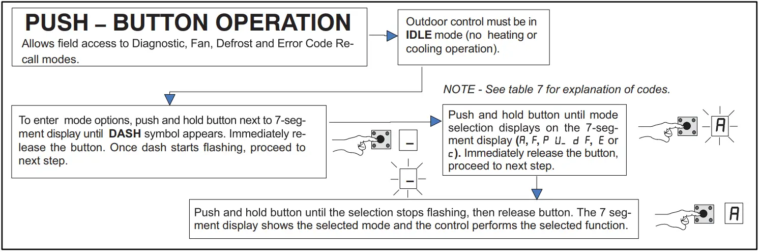 FIGURE 18. Push-Button Operation
Unit Selection Code for Outdoor Control
| If the single-character display shows three (3) horizontal lines, the unit selection code needs to be programmed. Press and hold the button until the P U menu option is displayed, and release the button. The single-character display displays the selected mode per example in figure 15 on page 36. When the desired unit selection code appears, press and hold the button until it stops flashing, then release. | ||
| Unit Code | Unit Type | Unit Model |
| 38 | 2-ton air conditioner | EL18XCVS024, EL18XCV-024 |
| 40 | 3-ton air conditioner | EL18XCVS036, EL18XCV-036 |
| 42 | 4-ton air conditioner | EL18XCVS048, EL18XCV-048 |
| 43 | 5-ton air conditioner | EL18XCVS060 |
| 30 | 5-ton air conditioner | EL18XCV-060 |
| Idle mode – System is energized with no demand – Decimal flashes at 1 Hertz > 0.5 second ON. 0.5 second OFF | ||
| Display Symbol or Character | Display | Fan Test and Display String Option |
| Displayed during start-up or power recycling | Display string shows outdoor control firmware version _ > pause > C or H P unit > pause > unit capacity in BTUs > pause > unit code. If 3 horizontal bars are displayed during any sequence of this display string, it indicates that the specific parameter is not configured. | |
| . | Idle mode — decimal flashes at 1 Hertz > 0.5 seconds ON, 0.5 seconds OFF | |
| Indicates Cooling Capacity. C1 or C2 if conventional 24VAC thermostat or demand percentage if S30 communicating the thermostat is used i.e. C 9 0 | ||
| Indicates you are in the outdoor fan test mode | The control must be in Idle mode: To enter fan test option – F mode, push and hold the button until solid – appears, and release the button. The display begins flashing. Within 10 seconds, push and hold the button until the required symbol F displays, and release the button. The display begins flashing. Within 10 seconds, push and hold the button until the display stops flashing, and release the button. Control will initiate outdoor fan operation. Outdoor fan cycles ON for 10 minutes at the highest speed. To exit the test – Push and hold the button until three horizontal bars display. Release button, outdoor fan cycles OFF. | |
| in the display, string represents the ambient temperature in °F at the sensor on the outdoor unit. | Control can be in Idle or demand mode: To enter the display configuration option – mode, push and hold the button until solid – appears, and release the button. The display begins flashing. Within 10 seconds, push and hold the button until the required symbol displays, the release button. The display begins flashing. Within 10 seconds, push and hold the button until the display stops flashing, and release the button. Display shows error (E) code(s) and ambient ( ), outdoor coil (c) and liquid (L) temperatures in Fahrenheit. NOTE – If the button is not pushed in the 10-second time period, the control exits the test mode. If this occurs, the test mode must be repeated. |
| Error Code Recall Mode (NOTE – control must be in idle mode) | |
| To enter error code recall mode, push and hold the button until solid E appears, then release the button. The control displays up to 10 error codes stored in memory. If E 0 0 0 0 is displayed, there are no stored error codes. |
| To exit error code recall mode, push and hold the button until solid three horizontal bars appear, then release the button. Note – Error codes are not cleared. | |
| To clear error codes stored in memory, continue to hold the button while the 3 horizontal bars are displayed. Release button when solid c is displayed. | |
| Push and hold for one (1) second, release button. 7-Segment displays 0 0 0 0 and exits error recall mode. |
FIELD TEST MODE OPERATION
The field test mode allows the unit to be put into diagnostic mode and allows the installer to perform multiple tests on the control/unit.
Diagnostic Mode
Diagnostic mode is only available when the system is idle or during an active / suspended call for heating or cooling.
Diagnostic mode is terminated when the exit command is given, the button is pressed and released without entering the diagnostic menu or 10 minutes have passed, whichever
comes first.
When this mode is selected all installed temperature sensor valves (non-open and non-short) are shown on the 7-segment display.
The following system status codes are displayed:
- Cooling
- Cooling stage or cooling percentage demand operation
- Active error codes
Outdoor Fan Mode
Diagnostic mode is only available while the system is in idle mode. This mode can be exited with the proper command or after 10 minutes has passed.
In diagnostic mode, the control energizes the outdoor fan at the highest speed.
CHARGE MODE OPERATION
To initiate the EL18XCV Charge Mode function, install the jumper across the two Charge Mode Pins (CHRG MODE) on the outdoor control. The Charge Mode can be used when charging the system with refrigerant, checking the refrigerant charge, pumping down the system, and per- forming other service procedures that require outdoor unit operation at 100% capacity.
EL18XCV Charge Mode Operation with an S30 iComfort Communicating Thermostat
Installing a jumper on the Charge Mode Pins will initiate compressor operation and outdoor fan motor at 100% capacity and will provide a signal to the indoor unit to initiate indoor blower operation at the maximum cooling air volume. To exit the charge mode, remove the Charge Mode Jumper. The Charge Mode has a maximum time of 60 minutes and will automatically exit the charge mode after 60 minutes is the charge mode jumper is left in place.
EL18XCV Charge Mode Operation with a Conventional 24VAC Non-Communicating Thermostat
On applications with a conventional 24VAC non-communicating thermostat, the charge mode jumper must be installed on the Charge Mode Pins after providing a Y1 cooling demand to the EL18XCV to initiate the Charge Mode. A cooling blower demand must also be provided to initiate blower operation on the cooling speed on the indoor unit. The compressor and outdoor fan motor will operate at 100% capacity. To exit the charging mode, remove the Charge Mode Jumper and remove the Y1 Cooling demand and indoor blower demand. The Charge Mode has a maximum time of 60 minutes and will automatically exit the charge mode after 60 minutes is the charge mode jumper is left in place.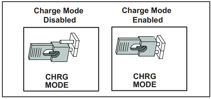
TABLE 9. Field Test, Diagnostic Recall and Program Menu Options
| TABLE 9. Field Test, Diagnostic Recall and Program Menu Options | |
| Display | Display and action (normal operation) |
| No Change – idle (*) | No Change – idle (*) |
| Solid. | Enter or exit field test and program mode. |
| Solid | Puts unit in diagnostic mode. (Displays ambient temperatures and any active error codes.) |
| Solid | Clears error history (**) |
| Solid | Enter diagnostic recall mode. Displays up to 10 error codes in memory. |
| Solid | Starts outdoor fan. |
| String | Enter unit code programming. |
*No change indicates the display will continue to show whatever is currently being displayed for normal operations.
**Note once the error history is deleted it cannot be recovered. After the history is deleted, the unit will reset itself.
| Display | Display and action (normal operation) | |
| . | Idle mode — decimal flashes at 1 Hertz > 0.5 seconds ON, 0.5 seconds OFF | |
| Cooling operation. Shows cooling stage C1 or C2 operating if non-communicating. Shows cooling capacity percentage i.e. operating if installed with an S30 communicating thermostat. Example: | |
| E in the display string represents the active error code(s) in the outdoor unit. Example: | |
| in the display, string represents the outdoor ambient temperature in °F at the outdoor sensor on the outdoor unit. Example: | ||
| Scrolling | When unit is in the charge mode, Suction pressure (SPxxx), Suction Temp (Stxx.x), Superheat (SHxx.x), Liquid pressure (LPxxx), Liquid Temp (Ltxx.x) and subcooling (SCxx.x) will be scrolled on the 7-segment display. Example: | |
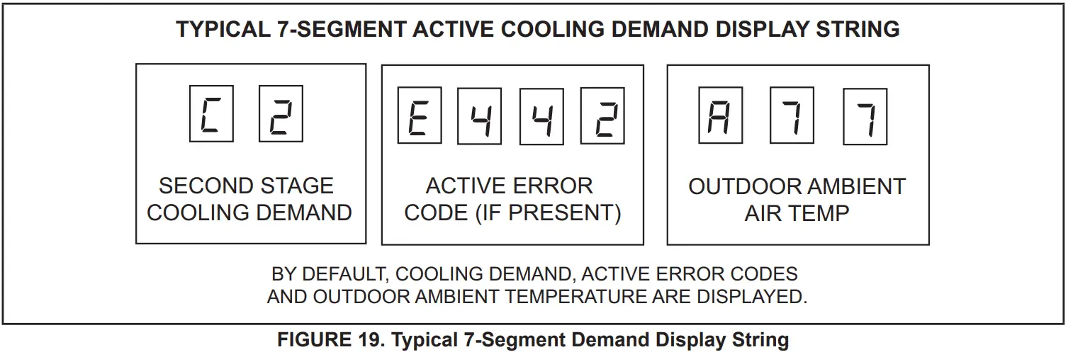
Configuring Unit
When installing a replacement outdoor control, the unit selection code may have to be manually assigned using the 7-segment display and push button on the control.
The unit code sets unit type, capacity and outdoor fan profile.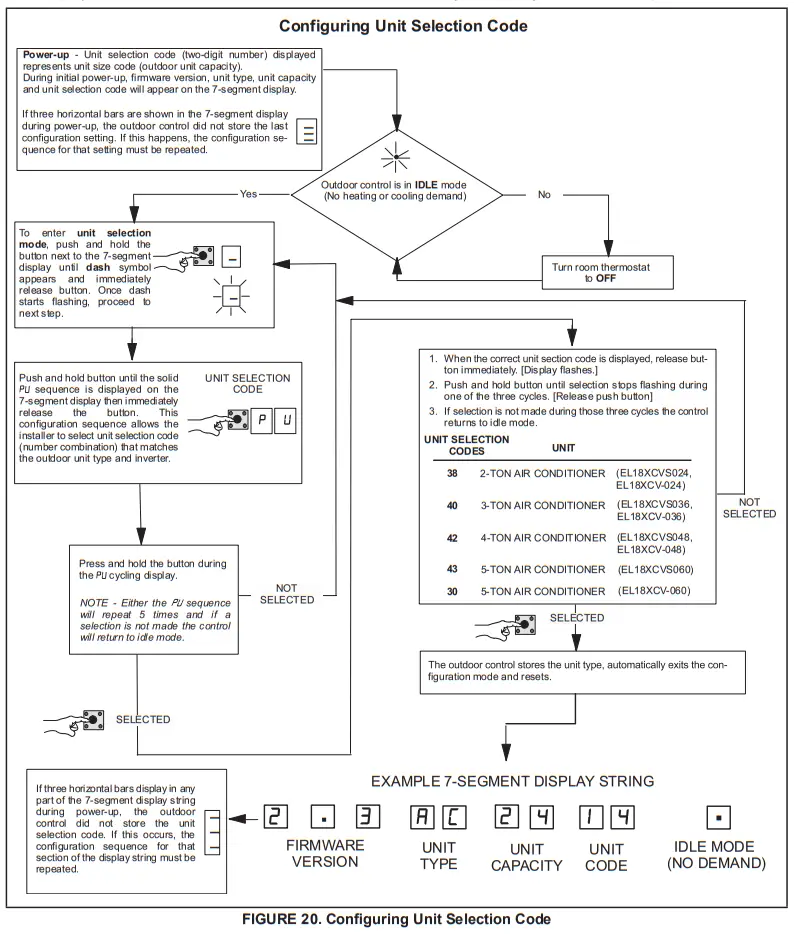
Reconfiguring Outdoor Control using iComfort® S30 Thermostat
Reconfiguring only applied to EL18XCV units installed as a fully communicating system with an iComfort S30 thermostat and communicating indoor unit. If any component of the HVAC system is changed, e.g. replacing an outdoor sensor, reconfiguring the system is required. To begin reconfiguring a system, select the Setup tab.
System Overview
Refer to the applicable Thermostat Installer Setup Guide
for configuration procedures.
The outdoor control provides the following functions:
- Internal switching of outputs.
- Compressor anti-short-cycle delay (adjustable through the thermostat interface).
- Five-strike lockout function.
- High-Pressure protection using the High Pressure
Switch (S4) and Low-Pressure Pressure protection using the Suction Pressure Transducer with setpoints that emulate a low-pressure switch. (Cut-out of 40 psig and cut-in of 90 psig). - Ambient (RT13), liquid line (RT36) and suction line (RT41) temperatures for monitoring and protection.
COMPRESSOR PROTECTION – FIVE-STRIKE LOCKOUT
The five-strike lockout function is designed to protect the compressor from damage. The five-strike feature is used for both high (S4) and low (S87) pressure switches. Resetting Five-Strike Lockout Once the condition has been rectified, power to the outdoor control R terminal must be cycled OFF.
Diagnostic Information – Installations with iComfort S30 Thermostat
The following diagnostic information is available through the thermostat’s user interface. Refer to the applicable In- staller System Setup Guide.
- Compressor anti-short-cycle delay timer status
- Cooling stage or cooling rate
- Compressor shift delay timer status
- High pressure switch status
- Suction pressure
- Compressor top cap switch status
- Liquid line and suction line temperature
- Outdoor ambient temperature
- Compressor active alarm
- Compressor Hz
- Inverter compressor short cycle
- Heat sink temperature
Installer Test – Installations with iComfort
S30 Thermostat
Verify the proper operation of the system by running the Installer Test feature through the thermostat interface. Refer to the applicable Installer System Setup Guide.
COMPRESSOR SHORT CYCLING DELAY
The outdoor control protects the compressor from:
- Short cycling (five minutes) during initial power-up.
- Interruption in power to the unit.
- Pressure or sensor trips.
- Delay after demand is removed.
The delay is set by default for 300 seconds (five minutes) but can be changed through the thermostat interface (iComfort S30 thermostat installations only). Available settings are 60, 120, 180, 240 and 300 seconds.
CRANKCASE HEATER (HR1)
Compressors in all units are equipped with a 40-watt bellyband-type crankcase heater. HR1 prevents liquid from accumulating in the compressor. HR1 is controlled by the crankcase heater thermostat.
CRANKCASE HEATER THERMOSTAT (S40)
Thermostat S40 controls the crankcase heater in all units. S40 is located on the liquid line. When liquid line temperature drops below 50°F, thermostat S40 closes, energizing HR1. The thermostat opens, de-energizing HR1, once the liquid line temperature reaches 70°F.
Maintenance
Outdoor Unit Maintenance and service must be performed by a qualified installer or service agency. At the beginning of each cooling season, the system should be checked as follows:
- Clean and inspect outdoor coil (may be flushed with a water hose). Ensure power is off before cleaning.
- Outdoor unit fan motor is factory-lubricated and sealed. No further lubrication is needed
- Visually inspect all connecting lines, joints and coils for evidence of oil leaks.
- Check all wiring for loose connections.
- Check for correct voltage at unit (unit operating).
- Check amp draw on outdoor fan motor.
- Inspect drain holes in coil compartment base and clean if necessary.
NOTE – If insufficient heating or cooling occurs, the unit should be gauged and the refrigerant charge should be checked.
Outdoor Coil
It may be necessary to flush the outdoor coil more frequently if it is exposed to substances which are corrosive or that block airflow across the coil (e.g., pet urine, cottonwood seeds, fertilizers, fluids that may contain high levels of corrosive chemicals such as salts).
• Outdoor Coil — The outdoor coil may be flushed with a water hose.
• Outdoor Coil (Coastal Area) — Moist air in ocean locations can carry salt, which is corrosive to most metal.
Units that are located near the ocean require frequent inspections and maintenance.
These inspections will determine the necessary need to wash the unit including the outdoor coil. Consult your installing contractor for proper intervals/procedures for your geographic area or service contract.
Indoor Unit
- Clean or change filters.
- Lennox blower motors are factory-lubricated and permanently sealed. No more lubrication is needed.
- Adjust blower speed for cooling. Measure the pressure drop over the coil to determine the correct blower CFM. Refer to the unit information service manual for pressure drop tables and procedures.
- Check all wiring for loose connections.
- Check for correct voltage at the unit. (blower operating)
- Check amp draw on the blower motor.
Indoor Coil
- Clean coil if necessary.
- Check connecting lines, joints, and coil for evidence of oil leaks.
- Check condensate line and clean if necessary.
Unit Wiring Diagrams
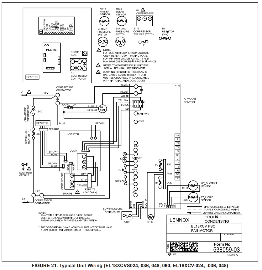
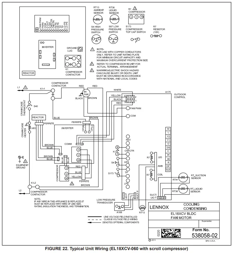
Factory Wiring Diagrams
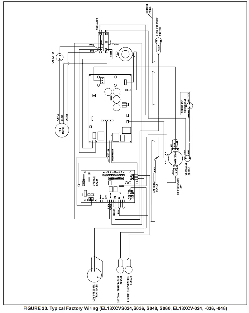
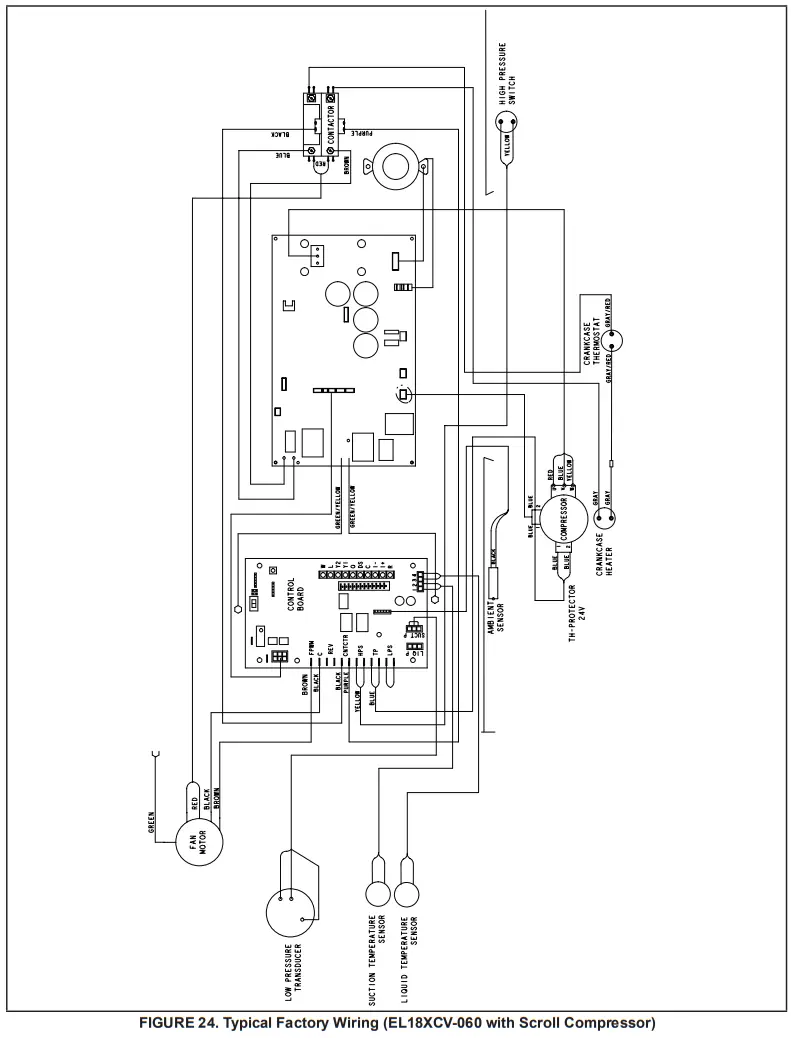
Unit Sequence of Operation
The following figures illustrate the overall unit sequence of operation along with the operation of various pressure switches and temperature sensors. The figures also illustrate the use of the compressor anti-short-cycle function in relation to unit Status, unit Fault and lockout LED Codes and unit system operation interactions.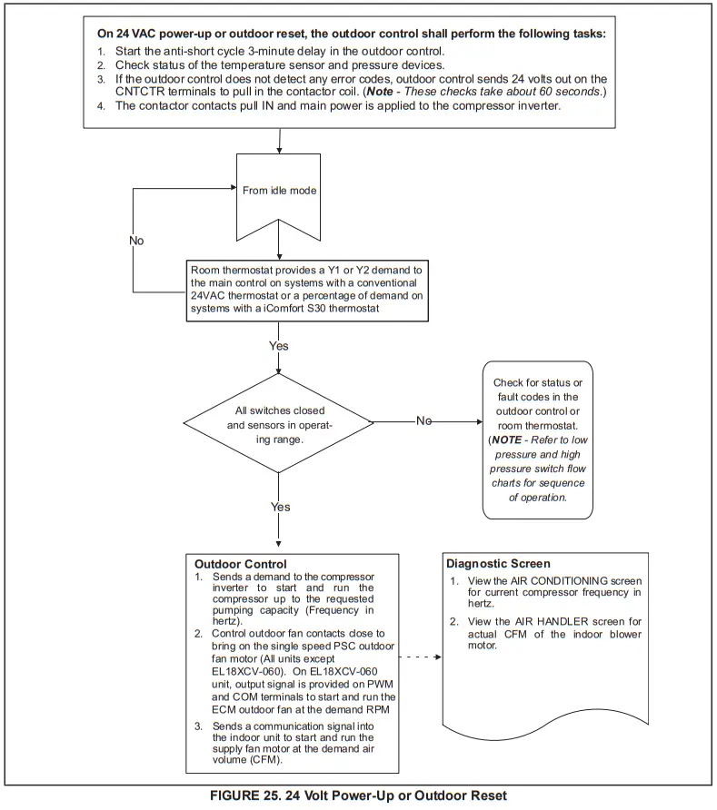
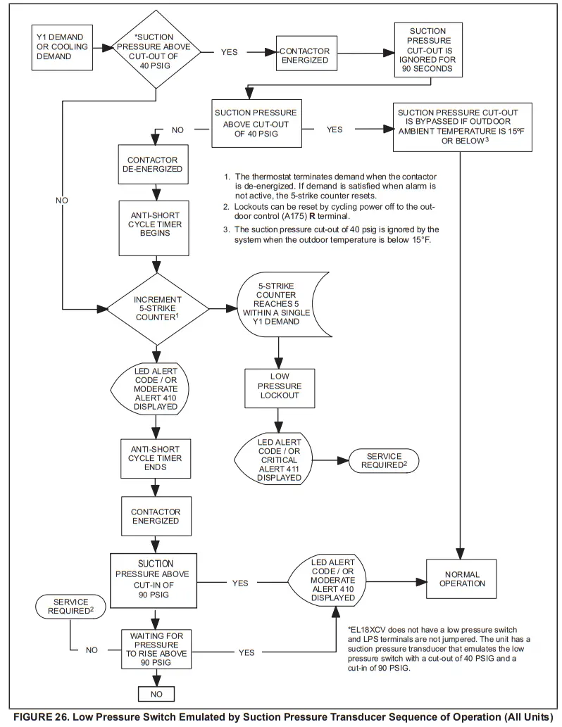
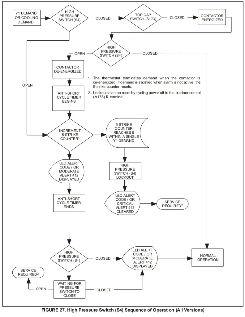
Verifying High-Pressure Switch and Low-Pressure Protection Operation
OPERATION:
The unit’s pressure S4 high-pressure switch is factory wired into the control on the HPS terminals.
NOTE – The EL18XCV does not have a low-pressure switch and LPS terminals are not jumpered. The unit has a suction pressure transducer that emulates the low-pressure switch with a cut-out of 40 PSIG and a cut-in of 90 PSIG. This provides the same protection as a traditional low-pressure switch. If the event the suction pressure transducer fails, backup protection is provided by the suction temperature sensor and will open at 25F.
Low Suction Pressure Protection – See figure 26 for the low suction pressure protection sequence of operation. High-Pressure Switch (HI-PS) – See figure 27 for the high-pressure switch sequence of operation.
Pressure Switch Event Settings
The following pressures are the auto-reset event value triggers for low and high-pressure thresholds:
- High Pressure (auto-reset) – trip at 590 PSIG; reset at 418.
- Low Suction Pressure Protection (Suction pressure transducer emulates LPS) (auto-reset) – trip at 40 psig; reset at 90.
CHECKOUT – S4 High-Pressure Switch
Using a multimeter set to ohms with the terminals disconnected from the control board, check the resistance between the two terminals of the pressure switch. If the resistance reading is 0 ohms, the switch is closed. 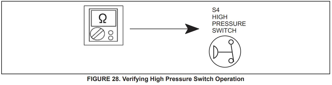
Verifying Suction Pressure Transducer Operation
Using a multimeter set to VDC with the Suction Pressure Transducer connected to the “Suct P” 3-pin connector on the control board. Pin 1 (Red wire +5VDC) to Pin 3 (Black wire – GND) should read 5 VDC continuous. Pin 2 (Blue wire output from transducer) to Pin 3 (Black – GND) should read 0.5 to 4.5 VDC and will vary depending on suction pressure measured. See Table 10.
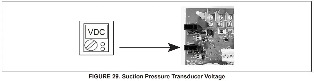
TABLE 10. Suction Pressure Transducer Output Voltage
| (PSIG) | (Pin 2 to Pin 3) | (PSIG) | (Pin 2 to Pin 3) |
| 0 | 0.49 | 110 | 2.69 |
| 10 | 0.69 | 120 | 2.89 |
| 20 | 0.89 | 130 | 3.09 |
| 30 | 1.09 | 140 | 3.29 |
| 40 | 1.29 | 150 | 3.49 |
| 50 | 1.49 | 160 | 3.69 |
| 60 | 1.69 | 170 | 3.89 |
| 70 | 1.89 | 180 | 4.09 |
| 80 | 2.09 | 190 | 4.29 |
| 90 | 2.29 | 200 | 4.49 |
| 100 | 2.49 | 210 | 4.5 |
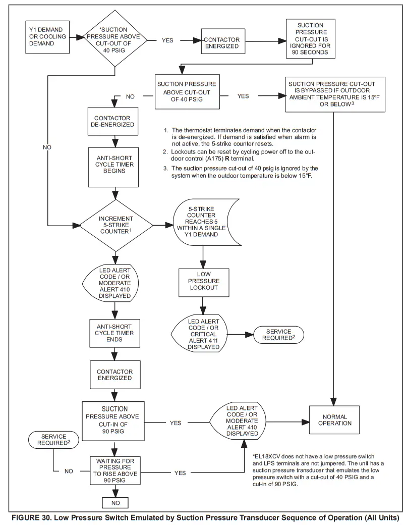
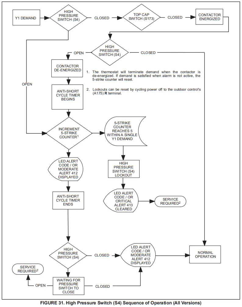
High-Pressure Switch and Low-Pressure Protection Errors
TABLE 11. Outdoor Control 7-Segment Display Alert Codes
| System fault and lockout codes take precedence over system status codes (cooling, heating operating percentages or defrost/dehumidification). Only the latest active fault or lockout codes are displayed (if present). If no fault or lockout codes are active, then system status codes are displayed. Alert codes are also displayed on the communicating thermostat. | |||
| Alert Codes | Priority | Alarm Description | Possible Causes and Clearing Alarm |
| E 410 | Moderate | The outdoor unit cycled off due to a low-pressure switch opening. | Unit pressure is below the lower limit. The system is shut down. The low-pressure switch closes above 90PSIG and opens below 40PSIG. Confirm that the system is properly charged with refrigerant. Check TXV, indoor unit blower motor, dirty filters, or clogged refrigerant filter. Confirm that the evaporator coil is clean. The alarm clears after the pressure switch opens or after a power reset. |
| E 411 | Critical | The low-pressure switch has opened 5 times within one hour. As a result, the outdoor unit is locked out. | The low-pressure switch error count reached 5 strikes. The low-pressure switch for HFC410A opens at 40PSIG and resets at 90PSIG. Confirm that the system is properly charged with refrigerant. Check for clogged TXV, blockage to the indoor unit blower motor, dirty filters, or clogged refrigerant filter. Confirm that the evaporator coil is clean. The alarm clears after a power reset. |
| E 412 | Moderate | The outdoor unit’s high-pressure switch has opened. | Unit pressure is above the upper limit. The system is shut down. The high-pressure switch opens at 590PSIG and closes at 418PSIG. Confirm that the system is properly charged with refrigerant. Check for clogged TXV, blockage to the indoor unit blower motor, and clogged refrigerant filter. Confirm that the outdoor unit is clean. The alarm clears after the pressure switch closes or a power reset. For heating, indoor CFM may be set too low. For the zoning system, zone CFM may be set too low. |
| E 413 | Critical | The high-pressure switch has opened 5 times within one hour. As a result, the outdoor unit is locked out. | Open high-pressure switch error count reached 5 strikes. The system is shut down. The high-pressure switch for HFC410A will open at 590PSIG and close at 418PSIG. Confirm that the system is properly charged with refrigerant. Check condenser fan motor, clogged TXV, blockage to the indoor unit blower motor, stuck reversing valve or clogged refrigerant filter. Confirm that the outdoor unit is clean. The alarm clears after indoor power reset (24VAC power source to Outdoor Control) |
Compressor Operation, Checkout and Status / Error Codes
OPERATION:
The EL18XCV uses two different types of compressors, depending on the specific model. The EL18XCVS024, S036, S048, S060, and EL18XCV-024, -036, and -048 use a 380VAC three-phase variable capacity rotary compressor specifically designed for unitary splits system and is approved for use with HFC 410A refrigerant. The EL18XCV-060 the unit uses a 380VAC three-phase variable-capacity scroll compressor that is approved for use with HFC 410A refrigerant. The compressor, when connected to an inverter, is
capable of operating in a running frequency range from 20 hertz up to a maximum of 69 hertz. (maximum hertz is dependent on compressor size). The compressor speed is determined by thermostat demand and suction pressure when installed with a conventional 24VAC non-communicating thermostat and by thermostat demand when installed with an iComfort S30 thermostat.
CHECKOUT:
NOTE – The compressor motor winding resistance is the nominal resistance at 77F. When measuring compressor motor winding resistance, the primary concern is the winding
the resistance between the different sets of terminals is within 10% of each other. The actual winding resistance is impacted by temperature, refrigerant and oil. Do not automatically condemn a compressor because the measured resistance is slightly higher or lower than the nominalresistance. Check for shorted/ open windings and for shorts to ground during testing.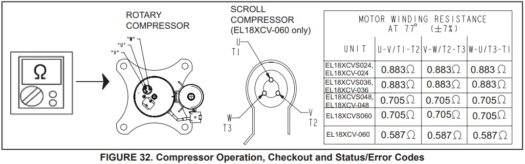
IMPORTANT: If compressor replacement is required, remove the compressor through the top of the unit. Removal through the access panel is not possible.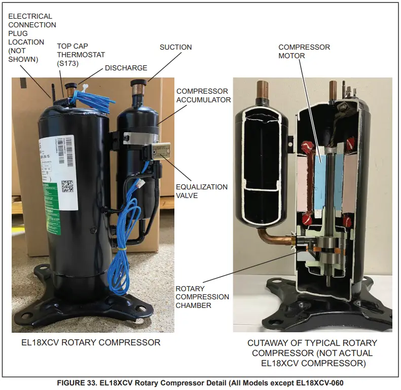
STATUS CODES:
When the compressor is running, the 7-segment display will show the compressor capacity. When the EL18XCV unit is installed with a Conventional 24VAC non- communicating thermostat the display will show C 1 or C 2. When the EL18XCV unit is installed with an iComfort S30 communicating thermostat the display will show the demand as a percentage. i.e. C 5 0.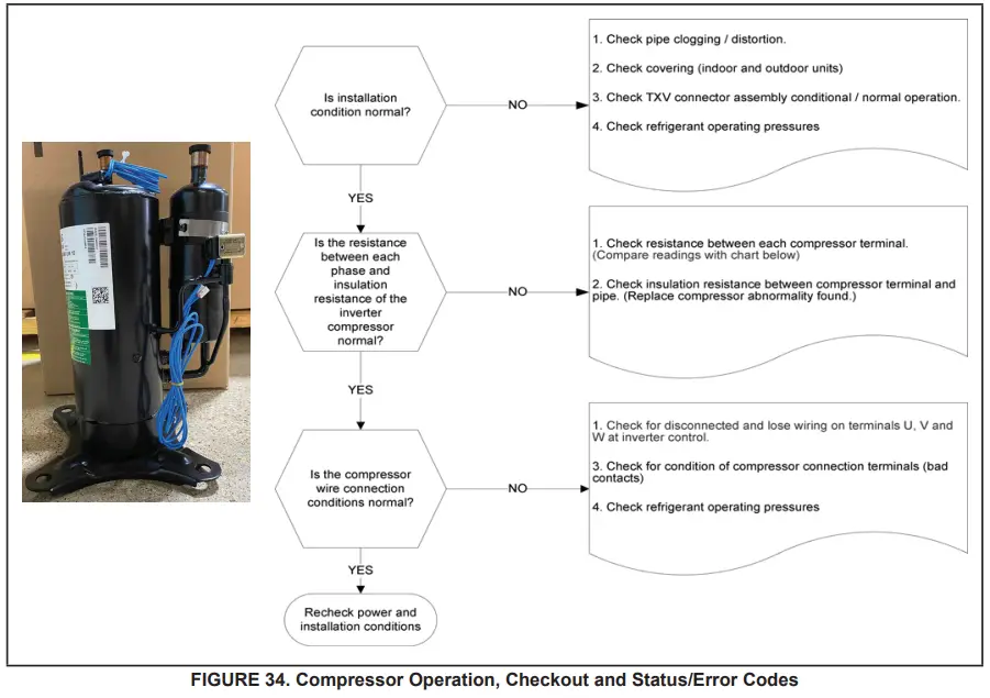
ERROR CODES:
TABLE 12. Outdoor Control 7-Segment Display Alert Codes – Compressor
System fault and lockout codes take precedence over system status codes (cooling, heating operating percentages or defrost/dehumidification). Only the latest active fault or lockout codes are displayed (if present). If no fault or lockout codes are active, then system status codes are displayed. Alert codes are also displayed on the S30 thermostat on systems installed with the S30 thermostat.
| Alert Codes | Inverter Code | Inverter LED Flash Code (number of flashes) | Priority | Alarm Description | Possible Causes and Clearing Alarm | |
| Red LED | Green LED | |||||
| E 430 | 26 | 2 flashes | 6 flashes | Moderate / Critical | Compressor start failure | If the condition is detected, the outdoor unit compressor and fan stop. Antishort cycle is initiated. If the condition occurs 10 times within an hour, the system is locked out. Indicates poor connection at compressor harness, improper winding resistance, locked compressor rotor, or flooded compressor. To clear, disconnect power to the indoor unit (24VAC power source to the outdoor control) which will power off the outdoor control and will open the outdoor unit contactor, which interrupts power to the inverter and then re-apply power. |
| E 433 | 11 | 2 flashes | 9 flashes | Moderate / Critical | The inverter has detected a compressor over-current condition. | The error occurs when compressor peak phase current is greater than 28A. Inverter issues code 14 first and slow down to try to reduce the current. If the current remains high, the outdoor unit compressor and fan stop. Antishort cycle is initiated. If the condition occurs 5 times within an hour. the system is locked out. To clear, disconnect power to the indoor unit (24VAC power source to the outdoor control) which will power off the outdoor control and will open the outdoor unit contactor, which interrupts power to the inverter and then re-apply power. |
| E 439 | 12 | 1flash | 2 flashes | Moderate | Compressor slowdown due to high input current. | Input current is approaching a high limit. Compressor speed automatically slows. The control continues sending the inverter speed demanded by the thermostat. The control sets indoor CFM and outdoor RPM to values according to demand percentage rather than the actual Hz. The alarm is automatically clear. |
| E 440 | 13 | 1 flash | 3 flashes | Minor | The heat sink temperature is approaching the limit. The compressor speed automatically slows to reduce heat sink temperature. The control sets indoor CFM and outdoor RPM to values according to demand percentage rather than the actual Hz. The alarm is automatically cleared. | This error code is primarily for informational purposes as the inverter controls the compressor speed to operate within design parameters. Typically the inverter will make a minor speed reduction of 4 Hz (approximately a 5-6% speed reduction) for a brief period of time to reduce the heat sink temperature and will then resume normal operation. This may occur at high outdoor temperatures (above 110°F) for brief periods of time (3 – 4 minutes) and is the normal and expected operation of the inverter controlling the compressor safely within design parameters. The inverter finned aluminum heat sink is located on the back side of the inverter in the condenser air stream. If alert code 440 occurs frequently, especially at lower outdoor temperatures, check the heat sink for debris that may reduce heat transfer or possible obstructions that may impact airflow across the heat sink. The inverter will begin to briefly reduce the compressor speed when the heat sink temperature rises above 185°F and will allow the inverter to resume the requested compressor demand speed once the inverter heat sink reaches 176°F. The heat sink temperature. compressor speed in Hertz & the Inverter Compressor Speed Reduction status (-On” or ‘Off “) notification can be viewed under the outdoor unit Diagnostics section of the thermostat dealer control center on units installed with an S30 thermostat. |
| E 441 | 14 | 1 flash | 4 flashes | Minor | Compressor slowdown due to high compressor current. The compressor current is approaching the limit. The compressor speed automatically slows. The control sets indoor CFM and outdoor RPM to values according to demand percentage rather than the actual Hz. The alarm is automatically cleared | This error code is primarily for informational purposes as the inverter controls the compressor to operate within design parameters. Alert code 441 typically occurs at startup as the compressor as current increases rapidly during startup. The inverter will reduce the compressor speed by 4 Hz and slow the compressor ramp-up speed to the requested compressor demand (capacity). This is the normal and expected operation of the inverter to control the compressor within design parameters. In most cases, the alert code 441 does not require any additional service or diagnostic procedures. E441 may also occur if the system is operating at high pressures. |
| E 600 | N/A | N/A | N/A | Critical | Compressor has been cycled OFF by utility load-shedding function. | Load-shedding function: Provides a method for a local utility company to limit the maximum power level usage of the outdoor unit. The feature is activated by applying 24 volts AC power to the L and C terminals on the outdoor control. |
Crankcase Heater, Checkout, and Status / Error Codes
OPERATION:
CRANKCASE HEATER (HR1)
Compressors in all units are equipped with a 40-watt belly-band type crankcase heater. The heater prevents liquid from accumulating in the compressor. The heater is controlled by the crankcase heater thermostat.
CRANKCASE HEATER THERMOSTAT (S40)
Crankcase heater thermostat S40 controls the crankcase heater in all units and is located on the liquid line (see figure 2 for location).
- When liquid line temperature drops below 50°F the thermostat closes which results in the heater being energized.
- When liquid line temperature rises above 70°F the thermostat opens which results in the heater being de-energized.
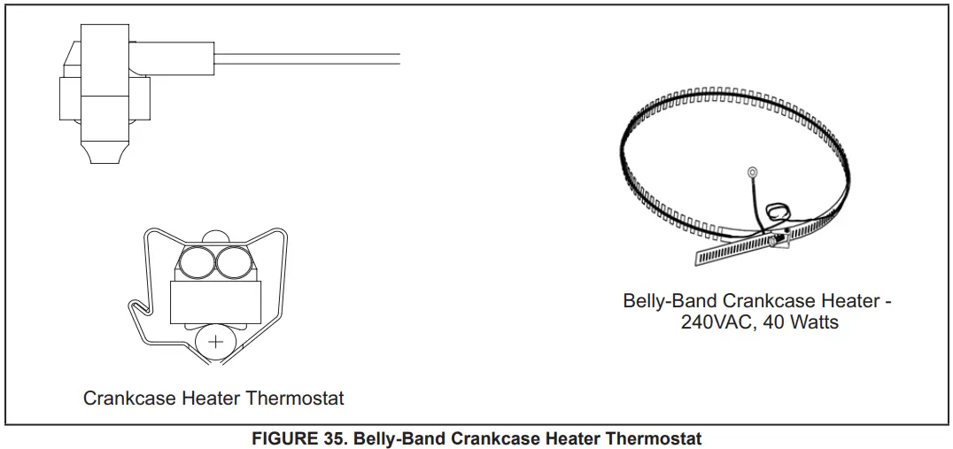
CHECKOUT:
Belly-Band Crankcase Heater: Using meter set on ohms, check crankcase heater resistance. If resistance is 0 ohms or infinite, replace the crankcase heater.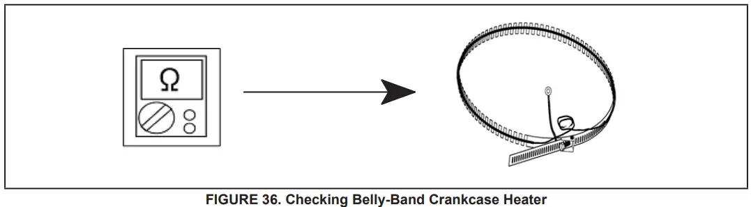
Crankcase Heater Thermostat: As the detected temperature changes, the resistance across the sensor changes. Table 17 on page 74 shows how the resistance varies as the temperature changes for this sensor.
NOTE – When checking the ohms across a sensor, be aware that a sensor showing a resistance value that is not within the range shown in table 15 on page 69, may be performing as designed. However, if a shorted or open circuit is detected, the sensor is faulty; the sensor needs to be replaced.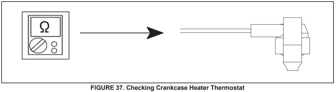
STATUS CODE:
None
ERROR CODES:
None
Compressor Sound Cover
All units come with a soft-sided polyethylene molded outer shell compressor sound cover. The cover helps reduce any unwanted operating sounds from the compressor. The cover features a hook/loop closure system for ease of installation on the compressor.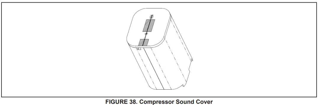
Suction Line Filter Drier (Rotary Compressor Models Only)
The EL18XCVS024, S036, S048, S060, and EL18XCV-024, -036, -048 have a rotary compressor and a factory-installed suction line filter drier installed in the suction line.
A liquid drier is not required but may be field installed. The filter drier is designed to remove moisture and foreign matter, which can lead to compressor failure.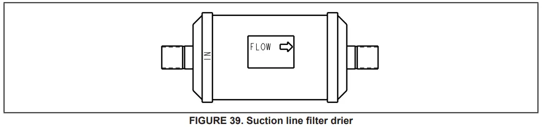
Liquid Line Filter Drier (EL18XCV-060 Scroll compressor model only)
The EL18XCV-060 has a scroll compressor and a liquid line filter drier that is factory-installed in the liquid line. The filter drier is designed to remove moisture and foreign matter, which can lead to compressor failure. The EL18XCV models with a rotary compressor do not have a factory-installed filter drier and it is not required on these models. A liquid line filter drier on the rotary compressor models may be field installed if desired.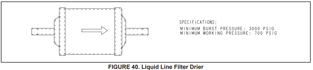
Top Cap Switch Operation, Checkout, and Status / Error Codes
OPERATION:
Top Cap Thermal Sensor Switch (S173)
Some units are equipped with a compressor-mounted normally closed temperature switch that prevents compressor damage due to overheating caused by internal friction. The switch is located on top of the compressor casing. This switch senses the compressor casing temperature and opens at 239-257°F to shut off compressor operation. The auto-reset switch closes when the compressor casing temperature falls to 151-187°F, and the compressor is re-energized. This is a single-pole, single-throw (SPST) bi-metallic switch.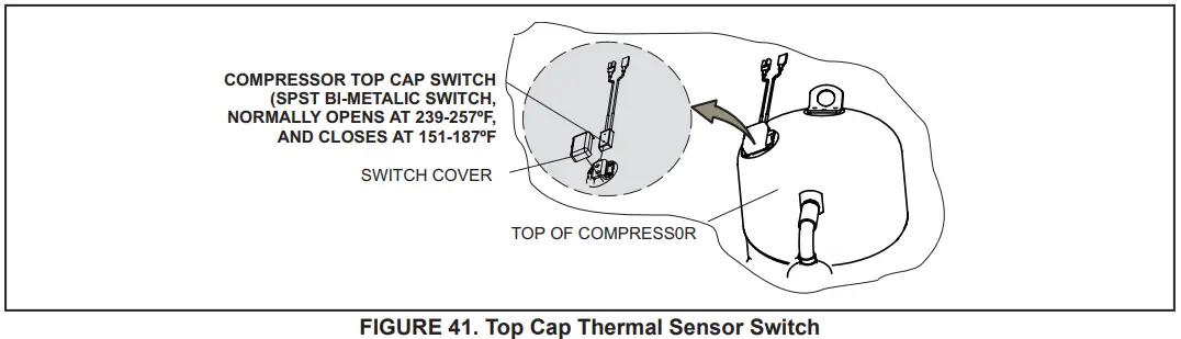
CHECKOUT:
Using a multimeter set to ohms, with the terminals disconnected from the system, check the resistance between the two terminals of the top cap switch. If the meter display does not change, the switch is open. If the meter display goes to infinite, the switch is closed.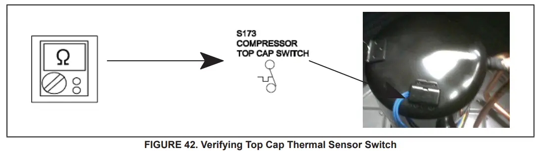
STATUS:
None
ERROR:
| TABLE 13. Outdoor Control 7-Segment Display Alert Codes – Top Cap Switch NOTE – System fault and lockout codes take precedence over system status codes (cooling, heating operating percentages or de- frost/dehumidification). Only the latest active fault or lockout codes are displayed (if present). If no fault or lockout codes are active, then system status codes are displayed. Alert codes are also displayed on the communicating thermostat. | |||
| Alert Codes | Priority | Alarm Description | Possible Causes and Clearing Alarm |
| E 422 | Moderate | Compressor top cap switch exceeding the thermal limit. | The top of the compressor is hot. A refrigerant charge may be low, or low mass flow of refrigerant. Check TXV, clogged filter drier, condenser fan motor, indoor blower motor, and confirm indoor coil is clean. Check to make sure the blue wires from the The top thermostat did not get pulled off one of the TP terminals on the outdoor control board. |
| E 442 | Critical | The top cap switch has opened 5 times within one hour. As a result, the outdoor unit is locked out. | When compressor thermal protection sensor opens 5 times within 1 hour, the outdoor stops working. To clear, disconnect power to the indoor unit (24VAC power source to the outdoor control) which will power off the outdoor control and will open the outdoor unit contactor, which interrupts power to the inverter and then re-apply power. |
Reactor Operations, Checkout, and Status / Error Codes
OPERATION:
A reactor (Inductor or choke) is a passive two-terminal electrical component that stores energy in its magnetic field. Read-tors are one of the basic components used in electronics where current and voltage change with time, due to the ability of inductors to delay and reshape alternating currents.
CHECKOUT:
Main Power ON – Voltage IN reactor should be the same as the voltage OUT. With main power OFF and reactor disconnected from the system; resistance between leads should be the same
STATUS CODES:
None
ERROR CODES:
None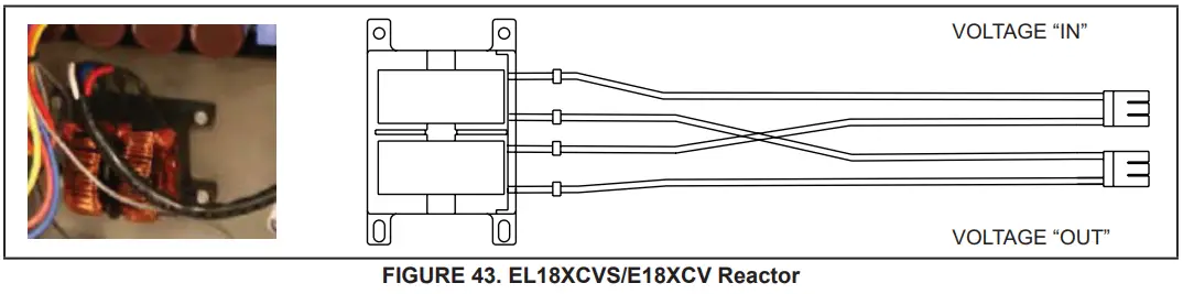
Outdoor Fan Operation and Checkout
OPERATION:
The EL18XCVS024, S036, S048, S060, and EL18XCV-024, -036, and -048 have a single-speed PSC outdoor fan motor that is controlled by the outdoor fan contacts located on the outdoor control. The outdoor fan motor will be energized anytime the compressor is running.
The EL18XCV-060 unit with the scroll compressor has a variable speed ECM fan motor. The variable speed ECM fan motor is controlled by PWM fan output when the compressor is running and will vary the fan speed to match the compressor capacity.
LOW AMBIENT OPERATION:
The EL18XCV units have factory installed low ambient operator that will control the condenser fan motor based upon liquid line temperature.
The EL18XCVS024, S036, S048, S060 and EL18XCV-024, -036 and -048 have a single speed PSC outdoor fan motor, and the outdoor control will begin to cycle the outdoor fan motor when the outdoor temperature is below 65°F and the liquid line sensor drops below 58°F and will cycle the fan back on when the liquid temperature rises above 70°F The EL18XCV-060 unit with the scroll compressor has a variable speed ECM fan motor. The outdoor control will begin to modulate the outdoor fan motor speed below 65°F to maintain a liquid line sensor temperature between 58°F and 70°F. If the liquid line sensor drops below 55°F the control will cycle the fan off until liquid temperature rises above 58°F.
CHECKOUT:
VAC Voltage Check
Check for 208/240 VAC power at inverter contactor (red wires) (see figure 44).
Units with PSC Motor:
- With the unit running, check for 230VAC at the Fan terminal on the outdoor control going to the motor. If no voltage is present check the main power at the contactor.
- Using the push button on the control, enter the “fan test mode” in the “field test mode” by pushing and holding the button until a solid “-” appears, and release the button. The display will start flashing, within 10 seconds, push and hold the button until the “F” symbol displays then release the button. The display will begin to flash “F”, within 10 seconds, push and hold the button until it stops flashing, and release the button. The outdoor fan motor will cycle on for 10 minutes. To exit, push and hold the button until three horizontal bars are displayed. Release the button and the outdoor fan will cycle off.
Units with ECM Motor (EL18XCV-060)
- With the unit running, check for 230VAC at the red outdoor fan motor wires at the contactor. If no voltage is present check the main power at the contactor.
- Perform a DC voltage check between the FPWM and Fan C terminal.
- Using the push button on the control, enter the “fan test mode” in the “field test mode” by pushing and holding the button until a solid “-” appears, and release the button. The display will start flashing, within 10 seconds, push and hold the button until the “F” symbol displays then release the button. The display will begin to flash “F”, within 10 seconds, push and hold the button until it stops flashing, and release the button. The outdoor fan motor will cycle on for 10 minutes. To exit, push and hold the button until three horizontal bars are displayed. Release the button and the outdoor fan will cycle off.
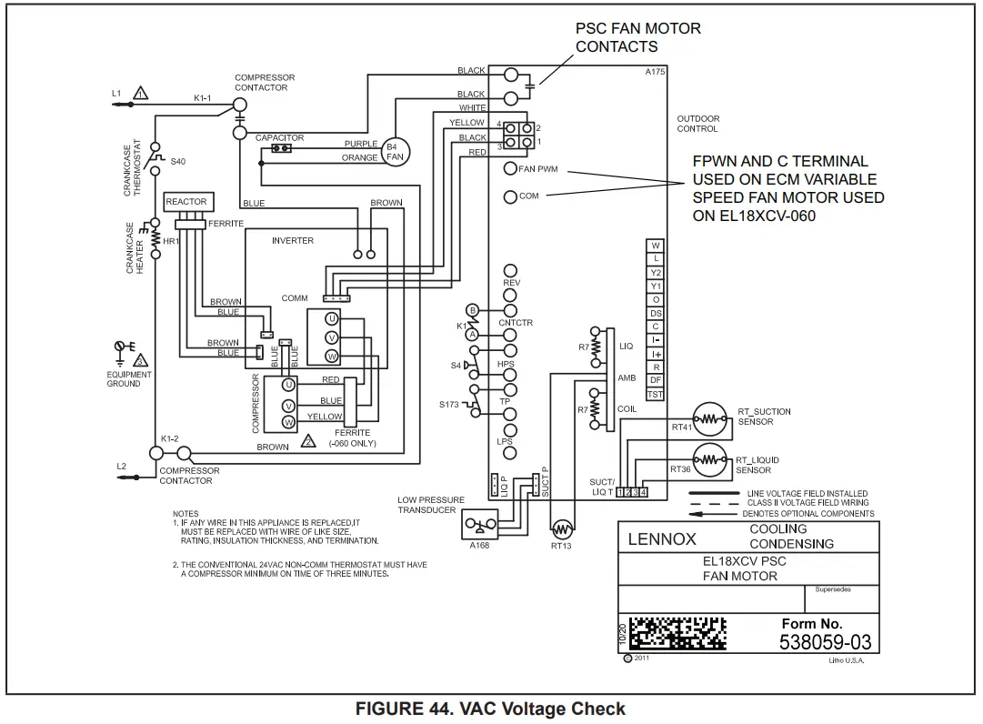
Outdoor Control Operation, Checkout, and Status / Error Codes OPERATION:
The outdoor control is a microprocessor-based device for use with variable-capacity compressors up to 5 tons in capacity operating on 24VAC residential power. The outdoor control integrates the functionality of maintaining compressor speed and outdoor fan control of PSC and ECM motors. The outdoor control is self-configuring. During start-up, the outdoor control selects one of two configurations variable-capacity air conditioner or a variable-capacity heat pump. The EL18XCV outdoor control provides application flexibility. The EL18XCV may be installed with an iComfort S30 communicating thermostat in a fully communicating system or with a conventional 24VAC non-communicating single or two-stage cooling thermostat.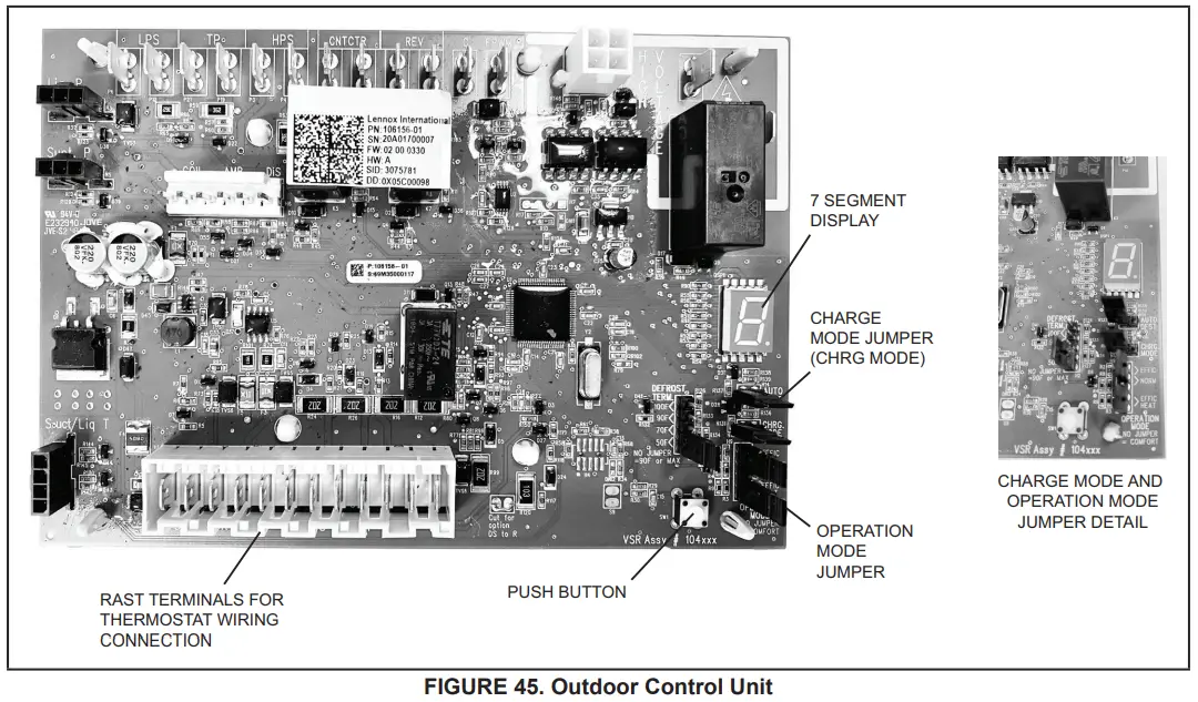
STATUS CODES:
| TABLE 14. Outdoor Control 7-Segment Display Alert Codes – Outdoor Control Status NOTE – System fault and lockout codes take precedence over system status codes (cooling, heating operating percentages or defrost/dehumidification). Only the latest active fault or lockout codes are displayed (if present). If no fault or lockout codes are active, then system status codes are displayed. Alert codes are also displayed on the iComfort® S30 thermostat. | |||
| Alert Codes | Priority | Alarm Description | Possible Causes and Clearing Alarm |
| E 600 | Critical | The compressor has been cycled OFF on utility load shedding | Load shedding function: Provides a method for a local utility company to limit the maximum power level usage of the outdoor unit. The feature is activated by applying 24 volts AC power to the L and C terminals on the outdoor control. |
| E 601 | Critical | The outdoor unit has been cycled OFF on low-temperature protection. | Low-temperature Protection: Outdoor unit will not operate when the outdoor temperature is at or below 4° F (20°C). If the unit is operating and the outdoor temperature drops below 4°F (20°C), the unit will continue to operate until the room thermostat is satisfied or the outdoor temperature drops to 15°F (26°C). (Outdoor unit ambient sensor provides temperature readings.) |
System Configuration
EL18XCV Thermostat Control Options
The EL18XCV variable capacity units provide two thermostat control options to provide application and installation flexibility.
iComfort S30 Communicating Thermostat Control
The E18XCV variable capacity unit may be installed as a fully communicating iComfort system consisting of an iComfort S30 Ultra Smart Communicating Thermostat, an iComfort enabled indoor unit and the EL18XCV variable-capacity outdoor unit wired with (4) iComfort communication wires (R, I+, I- and C) connected to the EL18XCV
Outdoor Unitary Control.
The EL18XCV variable capacity unit when wired as a fully communicating iComfort system will take full advantage of the advanced diagnostics and control, Wi-Fi accessibility, and system operation parameters. Refer to the EL18XCV field wiring diagram for an iComfort S30 communicating thermostat.
Conventional 24VAC Non-Communicating Thermostat Control
The EL18XCV variable capacity unit may be installed using a conventional 24VAC non-communicating two-stage cooling or single-stage cooling thermostat.
NOTE – The conventional 24VAC non-communicating thermostat must have a compressor minimum time of three minutes to prevent compressor short cycling. The Lennox M30, ComfortSense 7500, ComfortSense 3000, and many other commercially available electronic thermostats provide this feature.
The EL18XCV unit will provide full variable capacity operation when installed with a conventional 24VAC non-communicating two-stage cooling or single-stage cooling thermostat. The EL18XCV outdoor control has advanced control algorithms using the EL18XCV suction pressure sensor to provide true variable capacity operation. When utilizing a two-stage conventional 24VAC non-communicating thermostat, four wires are required to control the outdoor unit (R, C, Y1, and Y2). Refer to the EL18XCV field wiring diagram for a conventional 24VAC non-communicating 2-stage thermostat.
When utilizing a single conventional 24VAC non-communicating thermostat, three wires are required to control the outdoor unit (R, C, and Y1) and Y1 is jumpered to Y2 in the outdoor unit. Note that the published performance data is based upon the use of a two-stage thermostat. Refer to the EL18XCV field wiring diagram for a conventional 24VAC non-communicating single-stage thermostat.
EL18XCV Thermostat Control Options
| EL18XCV Thermostat Control Options | ||||
| Thermostat Type | Indoor Unit Type | Qty. of Wires to EL18XCV | EL18XCV Terminal Strip Connections | Unit Operation |
| iComfort S30 Communicating Thermostat | iComfort Communicating Gas Furnace or Air Handler | 4 | R, I+, I-, C | Fully Communicating Variable Capacity Operation Based Upon Thermostat Demand |
| Conventional 24VAC 2-Stage Cooling Thermostat (non-communicating) | Any Furnace or Air Handler (non-communicating or communicating) | 4 | R, C, Y1, Y2 | Full Variable Capacity Operation Controlled by EL18XCV Unitary Control Using Suction Pressure |
| Conventional 24VAC Single- tage Cooling Thermostat (non-communicating) | Any Furnace or Air Handler (non-communicating or communicating) | 3 | R, C, Y1 (Jumper Y1 to Y2) | Full Variable Capacity Operation Controlled by EL18XCV Unitary Control Using Suction Pressure |
Operation Mode Jumper
The Operation Mode Jumper is only used on applications installed with a conventional 24VAC Non-communicating thermostat. In applications with a conventional 24VAC non-communicating thermostat, the compressor capacity is controlled to maintain the target suction pressure setpoint. The Operation Mode Jumper has three selectable cooling modes.
The three modes are Efficiency (Jumper installed on Pins 1 & 2), Normal Mode (Jumper installed on Pins 2 & 3) and Comfort Mode (Jumper Removed). The factory default position is the Efficiency Mode. The Efficiency mode has a variable suction pressure setpoint that will vary with the outdoor temperature; as the outdoor temperature increases the suction pressure setpoint will decrease. When the Operation Mode jumper is installed in the “Normal Mode” the suction pressure setpoint is 135 psig.
Operation Mode Jumper (Conventional 24VAV Thermostats Only)
| Operation Mode Jumper | Jumper Position | Target Suction Pressure Setting |
| Efficiency (default) | Pin 1 to Pin 2 | Variable based on OAT |
| Normal | Pin 2 to Pin 3 | 135 PSIG |
| Comfort | Jumper Off | 125 PSIG |
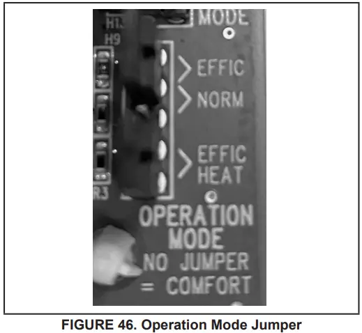
Unit Operation
EL18XCV Unit Operation with an S30 iComfort Communicating Thermostat When the EL18XCV unit is installed with a S30 iComfort Communicating Thermostat and comfort-enabled indoor unit, the unit capacity will be controlled in the variable capacity mode throughout the range of capacity from minimum capacity to maximum capacity based upon thermostat demand. The indoor air volume will be controlled to match cooling capacity throughout the capacity range.
EL18XCV Unit Operation with a Conventional 24VAC Non-Communicating 2-Stage Thermostat
When the EL18XCV unit is installed with a conventional 24VAC non-communicating 2-stage thermostat, a Y1 first stage cooling demand will initiate cooling operation and first stage indoor blower operation. The compressor will be controlled in the variable capacity mode by varying the compressor capacity to obtain the target suction pressure set point. The Y2 second stage cooling demand will initiate second stage blower operation. Increased air volume will increase the load on the indoor coil and increase the suction pressure. The EL18XCV compressor capacity will continue to be controlled based upon the suction pressure. The unit capacity will be controlled in the variable capacity mode throughout the range of capacity from minimum capacity to maximum capacity. If the Y2 demand remains after 20 minutes, the EL18XCV control will begin to ramp up the compressor capacity until maximum capacity is achieved. The EL18XCV unit will cycle off once the thermostat demand is satisfied.
EL18XCV Unit Operation with a Conventional 24VAC Non-Communicating Single-Stage Thermostat
When the EL18XCV unit is installed with a conventional 24VAC non-communicating single-stage thermostat, a Y1 first stage cooling demand will initiate cooling operation and cooling indoor blower operation. In single-stage thermostat applications, a jumper must be installed between Y1 and Y2 on the EL18XCV outdoor control. The compressor will be controlled in the variable capacity mode by varying the compressor capacity to obtain the target suction pressure set point. If the cooling demand remains after 20 minutes, the EL18XCV control will begin to ramp up the compressor capacity until maximum capacity is achieved. The EL18XCV unit will cycle off once the thermostat demand is satisfied.
ERROR CODES:
| TABLE 15. Outdoor Control 7-Segment Display Alert Codes – Outdoor Control Errors NOTE – System fault and lockout codes take precedence over system status codes (cooling, heating operating percentages or defrost/dehumidification). Only the latest active fault or lockout codes are displayed (if present). If no fault or lockout codes are active, then system status codes are displayed. Alert codes are also displayed on the iComfort® S30 thermostat. | |||
| Alert Codes | Priority | Alarm Description | Possible Causes and Clearing Alarm |
| E 105 | Moderate | The outdoor control has lost communication with either the thermostat or the indoor unit. | The equipment is unable to communicate. Indicates numerous message errors. In most cases, errors are related to electrical noise. Make sure high voltage power is separated from RSBus. Check for miswired and/or lose connections between the stat, indoor unit and outdoor unit. Check for a high voltage source of noise close to the system. Fault clears after communication is restored. |
| E 120 | Moderate | There is a delay in the outdoor unit responding to the system. | Typically, this alarm/code does not cause any issues and will clear on its own. The alarm/code is usually caused by a delay in the outdoor unit responding to the thermostat. Check all wiring connections. Cleared after unresponsive device responds to any inquiry. |
| E 124 | Critical | The iComfort S30® thermostat has lost communication with the outdoor unit for more than 3 minutes. | Equipment lost communication with the thermostat. Check the wiring connections, ohm wires and cycle power. The alarm stops all associated HVAC operations and waits for a heartbeat message from the unit that’s not communicating. The alarm/fault clears after communication is re-established. |
| E 125 | Critical | There is a hardware problem with the outdoor control. | There is a control hardware problem. Replace the outdoor control if the problem prevents operation and is persistent. The alarm/fault is cleared 300 seconds after the fault recovers |
| E 131 | Critical | The outdoor unit control parameters are corrupted | Reconfigure the system. Replace the control if heating or cooling is not available. |
| E 132 | Critical | Internal software error | Replace outdoor control. |
Unit Sensor Operation, Checkout and Status /Error Codes OPERATION:
6-Pin Sensor Harness (DIS, AMB, COIL)
Discharge Sensor (R7 – No Sensor)
There is no sensor located on positions 5 and 6 of the connector. A 10K Ohm resistor installed between pins 5 and 6 on the cable harness provides continuity for this circuit.
Ambient Temperature Sensor (RT13)
Ambient temperatures, as read by the ambient temperature sensor connected to pin 3 and pin 4, which are below -35°F (-37°C) or above 120°F (48°C) trigger a fault condition. If the ambient sensor is open, shorted, or out of the temperature range of the sensor, the control displays the appropriate alert code. Heating and cooling operation is allowed in this fault condition
Coil Temperature Sensor (R7 – No Sensor)
There is no sensor located on position 1 to position 2 of the connector. A 10K ohm resistor is installed between pins 1 and 2 on the cable harness and provides continuity for this circuit.
4-Pin Suction Temperature Sensor / Liquid Temperature Sensor Harness
Suction Line Sensor (RT41)
Suction line temperature is read by the suction line temperature sensor between Pins 1 and Pin 2 of the 4-pin sensor harness. The nominal Resistance of the sensor is 10K ohms at 77F. The control will display are E182 error code if the sensor reads open or shorted for 24 hours. Cooling operation is allowed with this fault.
Liquid Line Temperature Sensor (RT36)
Liquid line temperature is read by the liquid line temperature sensor between Pins 3 and Pin 4 of the 4-pin sensor harness.
The nominal Resistance of the sensor is 10K ohms at 77F. The control will display are E184 error code if the sensor reads open or shorted for 24 hours. Cooling operation is allowed with this fault.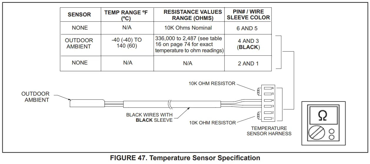
CHECKOUT:
Sensors connect to the outdoor control through a field-replaceable harness assembly that plugs into the outdoor control.
Through the sensors, the control detects outdoor ambient, coil, and liquid temperature fault conditions. As the detected temperature changes, the resistance across the sensor changes. Check sensor operation by reading ohms across pins shown in figure 49.
NOTE – When checking the ohms across a sensor, be aware that a sensor showing a resistance value that is not within the range shown in figure 49, may be performing as designed. However, if a shorted or open circuit is detected, then the sensor may be faulty and the sensor harness will need to be replaced.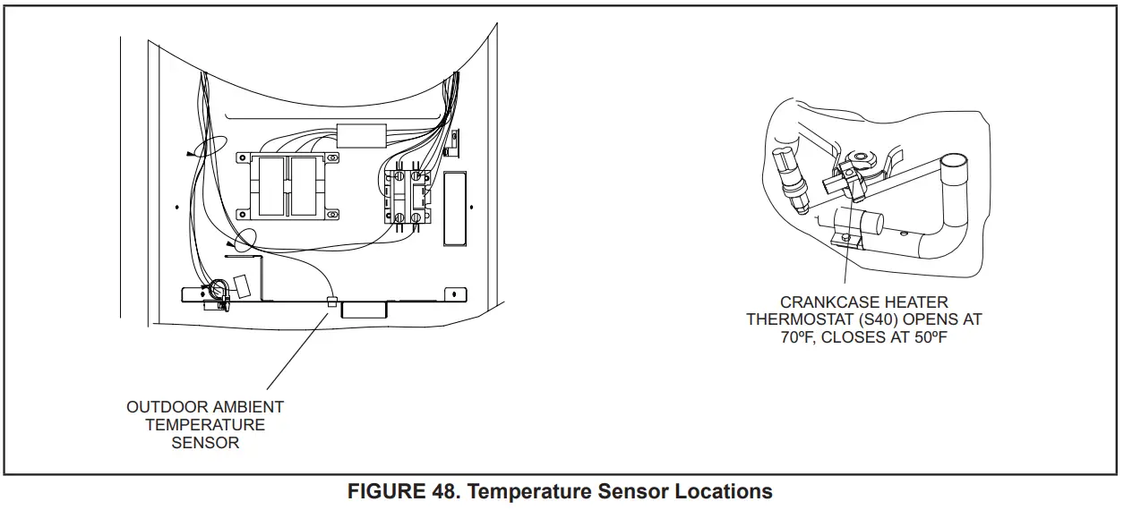
TABLE 16. Ambient and Liquid Line Sensors Temperature / Resistance Range
| inherit | Resistance | inherit | Resistance | inherit | Resistance | inherit | Resistance |
| 136.3 | 2680 | 56.8 | 16657 | 21.6 | 44154 | -11.3 | 123152 |
| 133.1 | 2859 | 56.0 | 16973 | 21.0 | 44851 | -11.9 | 125787 |
| 130.1 | 3040 | 55.3 | 17293 | 20.5 | 45560 | -12.6 | 128508 |
| 127.3 | 3223 | 54.6 | 17616 | 20.0 | 46281 | -13.2 | 131320 |
| 124.7 | 3407 | 53.9 | 17942 | 19.4 | 47014 | -13.9 | 134227 |
| 122.1 | 3592 | 53.2 | 18273 | 18.9 | 47759 | -14.5 | 137234 |
| 119.7 | 3779 | 52.5 | 18607 | 18.4 | 48517 | -15.2 | 140347 |
| 117.5 | 3968 | 51.9 | 18945 | 17.8 | 49289 | -15.9 | 143571 |
| 115.3 | 4159 | 51.2 | 19287 | 17.3 | 50074 | -16.5 | 146913 |
| 113.2 | 4351 | 50.5 | 19633 | 16.8 | 50873 | -17.2 | 150378 |
| 111.2 | 4544 | 49.9 | 19982 | 16.3 | 51686 | -17.9 | 153974 |
| 109.3 | 4740 | 49.2 | 20336 | 15.7 | 52514 | -18.6 | 157708 |
| 107.4 | 4937 | 48.5 | 20695 | 15.2 | 53356 | -19.3 | 161588 |
| 105.6 | 5136 | 47.9 | 21057 | 14.7 | 54215 | -20.1 | 165624 |
| 103.9 | 5336 | 47.3 | 21424 | 14.1 | 55089 | -20.8 | 169824 |
| 102.3 | 5539 | 46.6 | 21795 | 13.6 | 55979 | -21.5 | 174200 |
| 100.6 | 5743 | 46.0 | 22171 | 13.1 | 56887 | -22.3 | 178762 |
| 99.1 | 5949 | 45.4 | 22551 | 12.5 | 57811 | -23.0 | 183522 |
| 97.6 | 6157 | 44.7 | 22936 | 12.0 | 58754 | -23.8 | 188493 |
| 96.1 | 6367 | 44.1 | 23326 | 11.5 | 59715 | -24.6 | 193691 |
| 94.7 | 6578 | 43.5 | 23720 | 11.0 | 60694 | -25.4 | 199130 |
| 93.3 | 6792 | 42.9 | 24120 | 10.4 | 61693 | -26.2 | 204829 |
| 92.0 | 7007 | 42.3 | 24525 | 9.9 | 62712 | -27.0 | 210805 |
| 90.6 | 7225 | 41.7 | 24934 | 9.3 | 63752 | -27.8 | 217080 |
| 89.4 | 7444 | 41.1 | 25349 | 8.8 | 64812 | -28.7 | 223677 |
| 88.1 | 7666 | 40.5 | 25769 | 8.3 | 65895 | -29.5 | 230621 |
| 86.9 | 7890 | 39.9 | 26195 | 7.7 | 67000 | -30.4 | 237941 |
| 85.7 | 8115 | 39.3 | 26626 | 7.2 | 68128 | -31.3 | 245667 |
| 84.5 | 8343 | 38.7 | 27063 | 6.7 | 69281 | -32.2 | 253834 |
| 83.4 | 8573 | 38.1 | 27505 | 6.1 | 70458 | -33.2 | 262482 |
| 82.3 | 8806 | 37.5 | 27954 | 5.6 | 71661 | -34.1 | 271655 |
| 81.2 | 9040 | 37.0 | 28408 | 5.0 | 72890 | -35.1 | 281400 |
| 80.1 | 9277 | 36.4 | 28868 | 4.5 | 74147 | -36.1 | 291774 |
| 79.0 | 9516 | 35.8 | 29335 | 3.9 | 75431 | -37.1 | 302840 |
| 78.0 | 9757 | 35.2 | 29808 | 3.4 | 76745 | -38.2 | 314669 |
| 77.0 | 10001 | 34.7 | 30288 | 2.8 | 78090 | -39.2 | 327343 |
| 76.0 | 10247 | 34.1 | 30774 | 2.3 | 79465 | ||
| 75.0 | 10496 | 33.5 | 31267 | 1.7 | 80873 | ||
| 74.1 | 10747 | 33.0 | 31766 | 1.2 | 82314 | ||
| 73.1 | 11000 | 32.4 | 32273 | 0.6 | 83790 | ||
| 72.2 | 11256 | 31.9 | 32787 | 0.0 | 85302 | ||
| 71.3 | 11515 | 31.3 | 33309 | -0.5 | 86852 | ||
| 70.4 | 11776 | 30.7 | 33837 | -1.1 | 88440 | ||
| 69.5 | 12040 | 30.2 | 34374 | -1.7 | 90068 | ||
| 68.6 | 12306 | 29.6 | 34918 | -2.2 | 91738 | ||
| 67.7 | 12575 | 29.1 | 35471 | -2.8 | 93452 | ||
| 66.9 | 12847 | 28.6 | 36031 | -3.4 | 95211 | ||
| 66.0 | 13122 | 28.0 | 36600 | -4.0 | 97016 | ||
| 65.2 | 13400 | 27.5 | 37177 | -4.6 | 98870 | ||
| 64.4 | 13681 | 26.9 | 37764 | -5.2 | 100775 | ||
| 63.6 | 13964 | 26.4 | 38359 | -5.7 | 102733 | ||
| 62.8 | 14251 | 25.8 | 38963 | -6.3 | 104746 | ||
| 62.0 | 14540 | 25.3 | 39577 | -6.9 | 106817 | ||
| 61.2 | 14833 | 24.8 | 40200 | -7.5 | 108948 | ||
| 60.5 | 15129 | 24.2 | 40833 | -8.2 | 111141 | ||
| 59.7 | 15428 | 23.7 | 41476 | -8.8 | 113400 | ||
| 59.0 | 15730 | 23.2 | 42130 | -9.4 | 115727 | ||
| 58.2 | 16036 | 22.6 | 42794 | -10.0 | 118126 | ||
| 57.5 | 16345 | 22.1 | 43468 | -10.6 | 120600 | ||
ERROR CODES:
TABLE 17. Outdoor Control 7-Segment Display Alert Codes – Outdoor Control Errors
NOTE – System fault and lockout codes take precedence over system status codes (cooling, heating operating percentages or defrost/dehumidification).
Only the latest active fault or lockout codes are displayed (if present). If no fault or lockout codes are active, then system status codes are displayed.
Alert codes are also displayed on the iComfort® S30 thermostat.
| Alert Codes | Priority | Alarm Description | Possible Causes and Clearing Alarm |
| E 180 | Moderate / Critical | The iComfort S30 thermostat has found a problem with the outdoor unit’s ambient temperature sensor. | During normal operation, after the outdoor control recognizes sensors, the alarm will be sent only if the valid temperature reading is lost. Compare outdoor sensor resistance to temperature/resistance charts in unit installation instructions. Replace sensor pack if necessary. At the beginning of (any) configuration, furnace or air-handler control will detect the presence of the sensor(s). If detected (reading in range), the appropriate feature will be set as ‘installed’ and shown in the iComfort S30 thermostat ‘About’ screen. The alarm/fault will clear upon configuration, or sensing normal values. |
| E 182 | Moderate | The suction Temperature Sensor has malfunctioned | The sensor is open or shorted. Replace the Sensor |
| E 424 | Moderate | Faulty outdoor liquid line sensor | The sensor is open or shorted. Replace the sensor. |
OPERATION OF COMPONENTS:
Electromagnetic compatibility circuit (EMC): EMC ensures the correct operation of different equipment items which use or respond to electromagnetic phenomena. It also helps to negate the effects of interference.
CONVERTER:
Converts AC (alternating current) to DC (direct current).
POWER FACTOR CORRECTION (PFC) CIRCUIT:
The PFC module is an integrated part of the outdoor inverter that monitors the DC bus for high, low and abnormal voltage conditions. If any of these conditions are detected, the PFC function and compressor will stop.
INTELLIGENT (INVERTER) POWER MODULE (IPM):
The IPM converts DC power into AC power. The control method is known as pulse width modulation (PWM). This means the DC is switched on and off very quickly (chopped) by the transistor switches to make simulated AC at the required frequency and
voltage.
COMMUNICATION CONTROL CIRCUIT:
Receives and sends messages between the inverter and the outdoor control.
STATUS CODES:
| TABLE 18. Outdoor Control 7-Segment Display Alert Codes and Inverter LED Flash Codes NOTE – System fault and lockout codes take precedence over system status codes (cooling, heating operating percentages, or defrost/dehumidification). Only the latest active fault or lockout codes are displayed (if present). If no fault or lockout codes are active, then system status codes are displayed. Alert codes are also displayed on the iComfort® S30 thermostat. | |||||
| Alert Codes | Inverter LED Flash Code (number of flashes) | Prority | Alarm Description | Possible Causes and Clearing Alarm | |
| Red LED | Green LED | ||||
| N/A | ON | OFF | N/A | EL18XCVS024, 036, EL18XCV-024, -036 only: Indicates inverter is operating normally. | |
| N/A | ON | ON | N/A | EL18XCVS048, S060, EL18XCV-048, -060 only: Indicates inverter is operating normally. | |
| N/A | OFF | OFF | N/A | Indicates inverter is NOT energized. | |
ERROR CODES:
| TABLE 19. Outdoor Control 7-Segment Display Alert Codes and Inverter LED Flash Codes NOTE – System fault and lockout codes take precedence over system status codes (cooling, heating operating percentages or defrost/dehumidification). Only the latest active fault or lockout codes are displayed (if present). If no fault or lockout codes are active, then system status codes are displayed. Alert codes are also displayed on the iComfort® S30 thermostat. | ||||||
| Alert Codes | Inverter Code | Inverter LED Flash Code (number of flashes) | Priority | Alarm Description | Possible Causes and Clearing Alarm | |
| Red LED | Green LED | |||||
| E 423 | 40 | 4 flashes | OFF | Moderate / Critical | The inverter has detected a circuit problem. | Control will lock out after 10 strikes within an hour. To clear, disconnect power to the indoor unit (24VAC power source to the outdoor control) which will power off the outdoor control and will open the outdoor unit contactor, which interrupts power to the inverter and then re-apply power. |
| E 426 | N/A | N/A | N/A | Critical | Excessive inverter alarms | After ten faults within one hour, the control will lock out. Indicates poor system operation. Review history of alarms to resolve system setup. Check condenser fan motor, TXV, indoor unit blower motor, stuck reversing valve, over-charge, undercharge, and clogged refrigerant filter. To clear, disconnect power to the indoor unit (24VAC power source to the outdoor control) which will power off the outdoor control and will open the outdoor unit contactor, which interrupts power to the inverter and then re-apply power. Inverter alarms 12 to 14 and 53 do not count towards this lock-out condition. |
| E 427 | 21 | 2 flashes | 1 flash | Moderate / Critical | The inverter has detected a DC peak fault condition. | If a condition (55A or higher) is detected, the outdoor unit will stop (compressor and fan). Antishort cycle is initiated. If peak current (55A or higher) occurs 10 times within an hour, the system will lock out. Indicates high pressure, condenser fan failure, locked compressor rotor, or overcharge. To clear, disconnect power to the indoor unit (24VAC power source to the outdoor control) which will power off the outdoor control and will open the outdoor unit contactor, which interrupts power to the inverter and then re-apply power. |
| E 428 | 22 | 2 flashes | 2 flashes | Moderate / Critical | The inverter has detected a high main input current condition | If the condition is detected, the outdoor unit will stop (compressor and fan). Antishort cycle is initiated. If the condition occurs 5 times within an hour, the system will lock out. Indicates high pressure, condenser fan failure or overcharge. To clear, disconnect power to the indoor unit (24VAC power source to the outdoor control) which will power off the outdoor control and will open the outdoor unit contactor, which interrupts power to the inverter and then re-apply power. |
| E 429 | 23 | 2 flashes | 3 flashes | Moderate / Critical | On a call for compressor operation, if DC link power in the inverter does not rise above 180 VDC for 2 and 3-ton models, 250 VDC for 4 and 5-ton models, within 30 seconds, the control will display a moderate code. If the condition is detected, the outdoor unit will stop (Compressor and fan). Antishort cycles is initiated. If the condition occurs 10 times within a 60-minute rolling time period, the system will lock out and display a critical code. | Issues: (1) If DC link power in the inverter does not rise above 180 VDC for 2- and 3-ton models, and 250 VDC for 4- and 5-ton models, within 30 seconds, the outdoor control will display a moderate code. (2) Capacitors on the inverter do not properly charge. Corrective Actions: (1) Check for proper main power to the outdoor unit and for any loose electrical connections. |
| TABLE 19. Outdoor Control 7-Segment Display Alert Codes and Inverter LED Flash Codes NOTE – System fault and lockout codes take precedence over system status codes (cooling, heating operating percentages or defrost/dehumidification). Only the latest active fault or lockout codes are displayed (if present). If no fault or lockout codes are active, then system status codes are displayed. Alert codes are also displayed on the iComfort® S30 thermostat. | ||||||
| Alert Codes | Inverter Code | Inverter LED Flash Code (number of flashes) | Priority | Alarm Description | Possible Causes and Clearing Alarm | |
| Red LED | Green LED | |||||
| E 430 | 26 | 2 flashes | 6 flashes | Moderate / Critical | Compressor start failure. | If the condition is detected, outdoor unit will stop (compressor and fan). Antishort cycle is initiated. If the condition occurs 10 times within an hour, the system will lock out. Indicates poor connection at compressor harness, improper winding resistance, locked compressor rotor, or flooded compressor. To clear, disconnect power to the indoor unit (24VAC power source to the outdoor control) which will power off the outdoor control and will open the outdoor unit contactor, which interrupts power to the inverter and then re-apply power. |
| E 431 | 27 | 2 flashes | 7 flashes | Moderate / Critical | The error occurs when PFC detects an over-current condition of 100A, the control will display a moderate code. If the condition is detected, outdoor unit will stop (Compressor and fan). Anti-short cycle is initiated. The inverter is unavailable to communicate with the outdoor control for 3 minutes. If the condition occurs 10 times within a 60-minute rolling time period, the system will lock out and display a critical code. | Issues😐 (1) Indicates power interruption, brownout, poor electrical connection or loose inverter input wire.| (2) System testing was set up and code was generated when the reversing valve is de-energized coming out of defrosting (code appears with or without 30 compressor delay). Corrective Actions: (1) Check for proper main power to the outdoor unit and for any loose electrical connections. |
| E 432 | 28 | 2 flashes | 8 flashes | Moderate / Critical | The inverter has detected a DC link high voltage condition. | The error occurs when the DC link capacitor voltage is greater than 480VDC. If the condition is detected, outdoor unit will stop (compressor and fan). Antishort cycle is initiated. If the condition occurs 10 times within an hour, the system will lock out. The system will stop. To clear, disconnect power to the indoor unit (24VAC power source to the outdoor control) which will power off the outdoor control and will open the outdoor unit contactor, which interrupts power to the inverter and then re-apply power. |
| E 433 | 29 | 2 flashes | 9 flashes | Moderate / Critical | The inverter has detected a compressor over-current condition | The error occurs when the compressor peak phase current is greater than 28A. The inverter will issue code 14 first and slow down to try to reduce the current. If the current remains high, outdoor unit will stop (compressor and fan). Antishort cycle is initiated. If the condition occurs 5 times within an hour, the system will lock out. To clear, disconnect power to the indoor unit (24VAC power source to the outdoor control) which will power off the outdoor control and will open the outdoor unit contactor, which interrupts power to the inverter and then re-apply power. |
| TABLE 19. Outdoor Control 7-Segment Display Alert Codes and Inverter LED Flash Codes NOTE – System fault and lockout codes take precedence over system status codes (cooling, heating operating percentages or defrost/dehumidification). Only the latest active fault or lockout codes are displayed (if present). If no fault or lockout codes are active, then system status codes are displayed. Alert codes are also displayed on the iComfort® S30 thermostat. | ||||||
| Alert Codes | Inverter Code | Inverter LED Flash Code (number of flashes) | Priority | Alarm Description | Possible Causes and Clearing Alarm | |
| Red LED | Green LED | |||||
| E 434 | 53 | 5 flashes | 3 flashes | Moderate / Critical | Outdoor control has lost communications with the inverter for greater than 3 minutes. Outdoor unit will stop all compressor demand. Outdoor control will attempt to establish communication multiple times and will automatically clear when the error clears. Unit will lock out after 60 minutes if communication is not established and will display a critical error code. | Issues: (1) Outdoor disconnect is off or outdoor power is off, when indoor power is on (source for 24VAC) (2) Loose electrical power connections (3) Interruption of main power to the inverter (4) Generator powers the indoor unit, but not the outdoor unit. Corrective Actions: (1) To reset, cycle the indoor power off (source of 24VAC to outdoor unit) and back on. This will de- energize outdoor control and inverter by cycling the ontactor. (2) Make sure the disconnect is on (3) Check electrical power supply connections (4) Check for proper main 230V power supply |
| E 435 | 60 | 6 flashes | OFF | Moderate / Critical | Inverter internal error. | When this error occurs, the outdoor control will cycle power to the inverter by opening the contactor for 2 minutes. Check that the EEPROM is properly seated. After power is cycled to the inverter 3 times, the outdoor unit is locked out. |
| E 436 | 62 | 6 flashes | 2 flashes | Moderate / Critical | Inverter heat sink temperature exceeded the limit. Occurs when the heat sink temperature exceeds the inverter limit. Inverter issues code 13 first, then slows down to allow the heat sink to cool. If the temperature remains high, the outdoor unit stops (compressor and fan). Anti-short cycle is initiated. If the condition occurs 5 times within an hour, the system is locked out. To clear, disconnect power to the indoor unit (24VAC power source to the outdoor control) which will power off the outdoor control and will open the outdoor unit contactor, which interrupts power to the inverter and then re- apply power. |
Issue: Feedback from supplier tear down of inverter indicates that the screws that hold the inverter to the inverter board were loose causing poor contact between these two components. Corrective Action: Tighten screws that hold the heat sink to the inverter control board. NOTE: Wait five minutes to all capacitor to discharge before checking screws. |
| E 437 | 65 | 6 flashes | 5 flashes | Moderate / Critical | Heat sink temperature sensor fault has occurred (temperature less than 4 ºF or greater than 264ºF after 10 minutes of operation). | This occurs when the temperature sensor detects a temperature less than 0.4ºF or greater than 264ºF after 10 minutes of operation. If condition is detected, outdoor unit will stop (compressor and fan). Antishort cycle is initiated. If condition occurs 5 times within an hour, system will lock out. To clear, disconnect power to the indoor unit (24VAC power source to the outdoor control) which will power off the outdoor control and will open the outdoor unit contactor, which interrupts power to the inverter and then re-apply power. |
| TABLE 19. Outdoor Control 7-Segment Display Alert Codes and Inverter LED Flash Codes NOTE – System fault and lockout codes take precedence over system status codes (cooling, heating operating percentages or defrost/dehumidification). Only the latest active fault or lockout codes are displayed (if present). If no fault or lockout codes are active, then system status codes are displayed. Alert codes are also displayed on the iComfort® S30 thermostat. | ||||||
| Alert Codes | Inverter Code | Inverter LED Flash Code (number of flashes) | Priority | Alarm Description | Possible Causes and Clearing Alarm | |
| Red LED | Green LED | |||||
| E 438 | 73 | 7 flashes | 3 flashes | Moderate / Critical | The inverter has detected a PFC over the current condition. This would be caused by a high load condition, high pressure, or outdoor fan failure. Outdoor control will display the code when the inverter has the error. After 3 minutes, the inverter will reset and the compressor will turn on again. If it happens 10 times within a 60-minute rolling time period, the OD control will lock out the operation of the outdoor unit and display a critical code. | Issue: A possible issue is a system running at high pressures. Check for high-pressure trips or other alert codes in-room thermostats and outdoor control. |
| E 439 | 12 | 1 flash | 2 flashes | Minor | Compressor slowdown due to high input current. | This error code is primarily for informational purposes as the inverter controls the compressor to operate within design parameters. Typically the inverter will make a minor speed reduction of 4 Hz (approximately a 5-6% speed reduction) for a brief period of time and to reduce the input current and will then resume normal operation. |
| E 440 | 13 | 1 flash | 3 flashes | Minor | Heat sink temperature is approaching the limit. The compressor speed automatically slows to reduce heat sink temperature. The control sets indoor CFM and outdoor RPM to values according to demand percentage rather than the actual Hz. The alarm is automatically cleared. | This error code is primarily for informational purposes as the inverter controls the compressor speed to operate within design parameters. Typically the inverter will make a minor speed reduction of 4 Hz (approximately a 5-6% speed reduction) for a brief period of time and to reduce the heat sink temperature and will then resume normal operation. This may occur at high outdoor temperatures (above 110ºF) for brief periods of time (3 – 4 minutes) and is normal and expected operation of the inverter controlling the compressor safely within design parameters. The inverter finned aluminum heat sink is located on the back side of the inverter in the condenser air stream. f alert code 440 occurs frequently, especially at lower outdoor temperatures, check the heat sink for debris that may reduce heat transfer or possible obstructions that may impact airflow across the heat sink. The inverter will begin to briefly reduce the compressor speed when the heat sink temperature rises above 185ºF and will allow the inverter to resume the requested compressor demand speed once the inverter heat sink reaches 176ºF. The heat sink temperature, and compressor speed in Hertz & the Inverter Compressor Speed Reduction status (“On” or “Off ”) notification can be viewed under the outdoor unit Diagnostics section of the thermostat dealer control center on units installed with an S30 thermostat. |
| TABLE 19. Outdoor Control 7-Segment Display Alert Codes and Inverter LED Flash Codes NOTE – System fault and lockout codes take precedence over system status codes (cooling, heating operating percentages, or defrost/dehumidification). Only the latest active fault or lockout codes are displayed (if present). If no fault or lockout codes are active, then system status codes are displayed. Alert codes are also displayed on the iComfort® S30 thermostat. | ||||||
| Alert Codes | Inverter Code | Inverter LED Flash Code (number of flashes) | Priority | Alarm Description | Possible Causes and Clearing Alarm | |
| Red LED | Green LED | |||||
| E 441 | 14 | 1 flash | 4 flashes | Minor | Compressor slowdown due to high compressor current. The compressor current is approaching the limit. The compressor speed automatically slows. The control sets indoor CFM and outdoor RPM to values according to demand percentage rather than the actual Hz. The alarm is automatically cleared.. | This error code is primarily for informational purposes as the inverter controls the compressor to operate within design parameters. Alert code 441 typically occurs at startup as the compressor as current increases rapidly during startup. The inverter will reduce the compressor speed by 4 hz and slow the compressor ramp-up the speed to the requested compressor demand (capacity). This is the normal and expected operation of the inverter to control the compressor within design parameters. In most cases the alert code 441 does not require any additional service or diagnostic procedures. E441 may also occur if the system is operating at high pressures. This error code is primarily for informational purposes as the inverter controls the compressor to operate within design parameters. Alert code 441 typically occurs at startup as the compressor as current increases rapidly during startup. The inverter will reduce the compressor speed by 4 hz and slow the compressor ramp-up speed to the requested compressor demand (capacity). This is the normal and expected operation of the inverter to control the compressor within design parameters. In most cases the alert code 441 does not require any additional service or diagnostic procedures. E441 may also occur if the system is operating at high pressures. |
System Refrigerant
IMPORTANT
The system must be operating at full capacity during charging. Using the Charge Mode Jumper on the outdoor control ensures the unit is running at 100% capacity. Confirm outdoor unit running capacity.
This section outlines the procedures to:
- Connect a gauge set for testing and charging as illustrated in figure 49.
- Check and adjust indoor airflow as described in figure 50.
- Add or remove refrigerant using the weigh-in method shown in figure 51.
- Verify the charge using the subcooling method described in figure 52.
IMPORTANT: The unit must be operating at 100% capacity to be charged properly.
ADDING OR REMOVING REFRIGERANT
This system uses HFC-410A refrigerant which operates at much higher pressures than HCFC-22.
INDOOR AIRFLOW CHECK
Check airflow using the Delta-T (DT) process using the illustration in figure 50.
The diagnostic screen on the iComfort S30 thermostat displays the indoor CFMs on systems installed with the iComfort S30 communicating thermostat.
On systems installed with the S30 thermostat, the Cooling – Maximum Rate Test located in the Test section of the Dealer Control Center of the thermostat or the Dealer Setup App may be used to operate the unit at maximum capacity during charging.
Charge Mode Jumper
To initiate the EL18XCV Charge Mode function, install the jumper across the two Charge Mode Pins (CHRG MODE) on the outdoor control. The Charge Mode can be used when charging the system with refrigerant, checking the refrigerant charge, pumping down the system and per- forming other service procedures that requires outdoor unit operation at 100% capacity.
EL18XCV Charge Mode Operation with an S30 iComfort Communicating Thermostat
Installing a jumper on the Charge Mode Pins will initiate compressor operation and outdoor fan motor at 100% capacity and will provide a signal to the indoor unit to initiate indoor blower operation at the maximum cooling air volume. To exit the charge mode, remove the Charge Mode Jumper. The Charge Mode has a maximum time of 60 minutes and will automatically exit the charge mode after 60 minutes is the charge mode jumper is left in place.
EL18XCV Charge Mode Operation with a Conventional 24VAC Non-Communicating Thermostat
On applications with a conventional 24VAC non-communicating thermostat, the charge mode jumper must be installed on the Charge Mode Pins after providing a Y1 cooling demand to the EL18XCV to initiate the Charge Mode. A cooling blower demand must also be provided to initiate blower operation on the cooling speed on the indoor unit. The compressor and outdoor fan motor will operate at 100% capacity. To exit the charging mode, remove the Charge Mode Jumper and remove the Y1 Cooling demand and indoor blower demand. The Charge Mode has a maximum time of 60 minutes and will automatically exit the charge mode after 60 minutes is the charge mode jumper is left in place.
GAUGE SET
CONNECTIONS FOR TESTING AND CHARGING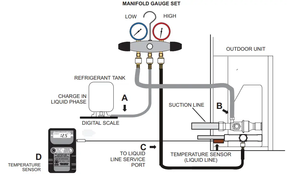
A. CLOSE MANIFOLD GAUGE SET VALVES AND CONNECT THE CENTER HOSE TO A CYLINDER OF HFC-410A SET FOR LIQUID PHASE CHARGING.
B. CONNECT THE MANIFOLD GAUGE SET’S LOW-PRESSURE SIDE TO THE SUCTION LINE SERVICE PORT.
C. CONNECT THE MANIFOLD GAUGE SET’S HIGH-PRESSURE SIDE TO THE LIQUID LINE SERVICE PORT.
D. POSITION TEMPERATURE SENSOR ON LIQUID LINE NEAR LIQUID LINE SERVICE PORT.
FIGURE 49. Gauge Set Connections
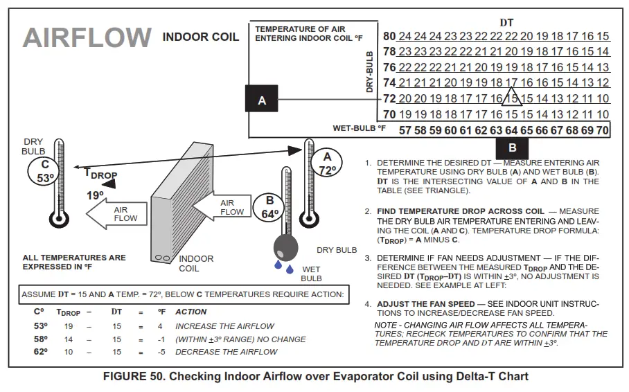
Use the WEIGH-IN method for adding the initial refrigerant charge, and then use the SUBCOOLING method for verifying the refrigerant charge.
WEIGH-IN
CHARGING METHOD
64ºF (17.7ºC) and Below Adjust the amount for variation in line set length and liquid line diameter using the table below.
Amount specified on nameplate To tal charge
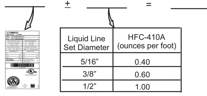
NOTE – Insulate the liquid line when it is routed through areas where the surrounding ambient temperature could become higher than the temperature of the liquid line or when pressure drop is equal to or greater than 20 psi.
NOTE – The nameplate is shown for illustration purposes only. Go to the actual nameplate on the outdoor unit for charge information.
Charging Formula for Liquid Line Charge Adjustments [(Line set oz./ft. x total length) – (factory charge for line set)] = charge adjustment Example: Units are factory-charged for 15 feet (4.6 meters) of a 3/8″ line set.
Factory charge for 3/8″ is 0.60 oz/ft x 15 = 9.0 ounces.
FIGURE 51. Using HFC-410A Weigh-In Method
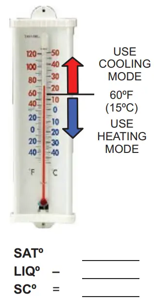
SUBCOOLING CHARGING METHOD
(All charging MUST be performed while the system is operating either at maximum speed or 100% demand.)
- THE DIAGNOSTIC SCREEN ON THE THERMOSTAT OR OUTDOOR CONTROL 7-SEGMENT DISPLAY WILL SHOW INDOOR AND OUTDOOR MOTOR CFMS OR RPMS.
- MEASURE OUTDOOR AMBIENT TEMPERATURE.
- CONNECT GAUGE SET.
- CHECK LIQUID AND VAPOR LINE PRESSURES. COMPARE PRESSURES WITH COOLING MODE NORMAL OPERATING PRESSURES IN THE APPLICABLE CHARGING STICKER, AND NORMAL OPERATING PRESSURES AT MAXIMUM CAPACITY. NOTE – THE REFERENCE TABLE IS A GENERAL GUIDE. EXPECT MINOR PRESSURE VARIATIONS. SIGNIFICANT DIFFERENCES MAY MEAN IMPROPER CHARGE OR OTHER SYSTEM PROBLEMS.
- SET THERMOSTAT FOR HEAT/COOL DEMAND, DEPENDING ON THE MODE BEING USED:
USING COOLING MODE — WHEN THE OUTDOOR AMBIENT TEMPERATURE IS 60°F (15°C) AND ABOVE. TARGET SUBCOOLING VALUES (MAXIMUM / 100% CAPACITY) IN APPLICABLE CHARGING STICKER ARE BASED ON 70 TO 80°F (21-27°C) INDOOR RETURN AIR TEMPERATURE; IF NECESSARY, OPERATE HEATING TO REACH THAT TEMPERATURE RANGE; THEN SET THE INITIAL COOLING DEMAND AT MAXIMUM CAPACITY. THE PREFERRED METHOD IS TO USE THE “CHARGE MODE” JUMPER ON THE OUTDOOR CONTROL. SEE CHARGE MODE JUMPER SECTION ON PAGE 80. WHEN PRESSURES HAVE STABILIZED, CONTINUE WITH STEP 6. - READ THE LIQUID LINE TEMPERATURE; RECORD IN THE LIQº SPACE.
- READ THE LIQUID LINE PRESSURE; THEN FIND ITS CORRESPONDING TEMPERATURE IN THE TEMPERATURE/ PRESSURE CHART LISTED IN THE APPLICABLE CHARGING STICKER AND RECORD IT IN THE SATº SPACE.
- SUBTRACT LIQº TEMPERATURE FROM SATº TEMPERATURE TO DETERMINE SUBCOOLING; RECORD IT IN SCº SPACE.
- COMPARE SCº RESULTS WITH APPLICABLE CHARGING STICKER, BEING SURE TO NOTE ANY ADDITIONAL CHARGE FOR
LINE SET AND/OR MATCH-UP. - IF THE SUBCOOLING VALUE IS GREATER THAN SHOWN IN THE APPLICABLE CHARGING STICKER FOR THE APPLICABLE UNIT,
REMOVE REFRIGERANT; IF LESS THAN SHOWN, ADD REFRIGERANT. - IF REFRIGERANT IS ADDED OR REMOVED, REPEAT STEPS 6 THROUGH 10 TO VERIFY THE CHARGE.
- DISCONNECT THE GAUGE SET AND RE-INSTALL BOTH THE LIQUID AND SUCTION SERVICE VALVE CAPS.
FIGURE 52. Using HFC-410A Subcooling Method – High Speed (High Capacity)
TABLE 20. HFC-410A Temperature (°F) – Pressure (Psig)
| °F | Psig | °F | Psig | °F | Psig | °F | Psig | °F | Psig | °F | Psig | °F | Psig | °F | Psig |
| 32 | 100.8 | 48 | 137.1 | 63 | 178.5 | 79 | 231.6 | 94 | 290.8 | 110 | 365.0 | 125 | 445.9 | 141 | 545.6 |
| 33 | 102.9 | 49 | 139.6 | 64 | 181.6 | 80 | 235.3 | 95 | 295.1 | 111 | 370.0 | 126 | 451.8 | 142 | 552.3 |
| 34 | 105.0 | 50 | 142.2 | 65 | 184.3 | 81 | 239.0 | 96 | 299.4 | 112 | 375.1 | 127 | 457.6 | 143 | 559.1 |
| 35 | 107.1 | 51 | 144.8 | 66 | 187.7 | 82 | 242.7 | 97 | 303.8 | 113 | 380.2 | 128 | 463.5 | 144 | 565.9 |
| 36 | 109.2 | 52 | 147.4 | 67 | 190.9 | 83 | 246.5 | 98 | 308.2 | 114 | 385.4 | 129 | 469.5 | 145 | 572.8 |
| 37 | 111.4 | 53 | 150.1 | 68 | 194.1 | 84 | 250.3 | 99 | 312.7 | 115 | 390.7 | 130 | 475.6 | 146 | 579.8 |
| 38 | 113.6 | 54 | 152.8 | 69 | 197.3 | 85 | 254.1 | 100 | 317.2 | 116 | 396.0 | 131 | 481.6 | 147 | 586.8 |
| 39 | 115.8 | 55 | 155.5 | 70 | 200.6 | 86 | 258.0 | 101 | 321.8 | 117 | 401.3 | 132 | 487.8 | 148 | 593.8 |
| 40 | 118.0 | 56 | 158.2 | 71 | 203.9 | 87 | 262.0 | 102 | 326.4 | 118 | 406.7 | 133 | 494.0 | 149 | 601.0 |
| 41 | 120.3 | 57 | 161.0 | 72 | 207.2 | 88 | 266.0 | 103 | 331.0 | 119 | 412.2 | 134 | 500.2 | 150 | 608.1 |
| 42 | 122.6 | 58 | 163.9 | 73 | 210.6 | 89 | 270.0 | 104 | 335.7 | 120 | 417.7 | 135 | 506.5 | 151 | 615.4 |
| 43 | 125.0 | 59 | 166.7 | 74 | 214.0 | 90 | 274.1 | 105 | 340.5 | 121 | 423.2 | 136 | 512.9 | 152 | 622.7 |
| 44 | 127.3 | 60 | 169.6 | 75 | 217.4 | 91 | 278.2 | 106 | 345.3 | 122 | 428.8 | 137 | 519.3 | 153 | 630.1 |
| 45 | 129.7 | 61 | 172.6 | 76 | 220.9 | 92 | 282.3 | 107 | 350.1 | 123 | 434.5 | 138 | 525.8 | 154 | 637.5 |
| 46 | 132.2 | 62 | 175.4 | 77 | 224.4 | 93 | 286.5 | 108 | 355.0 | 124 | 440.2 | 139 | 532.4 | 155 | 645.0 |
| 47 | 134.6 | 78 | 228.0 | 109 | 360.0 | 140 | 539.0 |
FIGURE 53. EL18XCV Charging Label
| Charging Temperatures and Pressures – High Speed Only | |||||
| EL18XCV Unit | -024 | -036 | -048 | -060 | -S060 |
| Table 1 – Subcooling Values (High Capacity) Saturation Temperature minus Liquid Temperature °F (°C) ± 1°F (0.5°C) | |||||
| Temp. °F (°C) | 11 (6.1) | 12 (6.7) | 10 (5.6) | 10 (5.6) | 11 (6.1) |
| Table 2 – Approach Values (High Capacity) Liquid Line Temperature minus Outdoor Ambient Temperature °F (°C) ± 1°F (0.5°C) | |||||
| Temp. °F (°C) | 6 (3.3) | 7 (3.9) | 7 (3.9) | 6 (3.3) | 6 (3.3) |
| Table 3 – Normal Operating Pressures (Liquid ± 10 / Suction ± 5 psig) | |||||
| Air Temp Entering Outdoor Coil | The values below are typical pressures; indoor evaporator match-up, indoor air quantity, and evaporator load will cause the pressure to vary. Liquid Line Pressure / Vapor Line Pressure | ||||
| 65 (18.3) | 243/141 | 252/136 | 239/134 | 236/124 | 252/130 |
| 70 (21.1) | 260/143 | 270/138 | 258/135 | 256/128 | 272/131 |
| 75 (23.9) | 281/144 | 291/138 | 279/136 | 275/131 | 293/132 |
| 80 (26.6) | 302/145 | 314/139 | 299/137 | 296/133 | 315/133 |
| 85 (29.4) | 325/146 | 336/141 | 322/138 | 317/135 | 339/135 |
| 90 (32.2) | 349/147 | 359/142 | 345/139 | 339/136 | 362/135 |
| 95 (35.0) | 376/148 | 384/144 | 369/141 | 365/138 | 387/136 |
| 100 (37.7) | 400/149 | 409/144 | 393/142 | 389/140 | 413/137 |
| 105 (40.6) | 436/151 | 436/145 | 419/143 | 414/141 | 440/138 |
| 110 (43.3) | 456/152 | 465/146 | 445/144 | 442/142 | 469/140 |
| 115 (46.1) | 486/153 | 494/148 | 473/146 | 472/143 | 499/141 |
![]()


