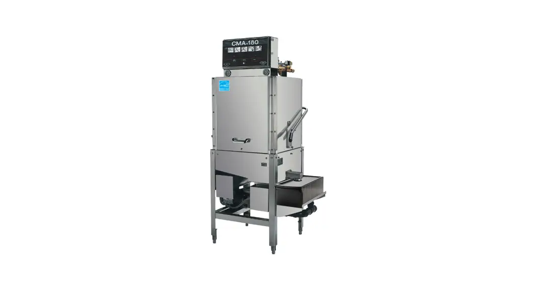
![]() CMA-180 Single Rack High Temperature
CMA-180 Single Rack High Temperature
Owner’s Manual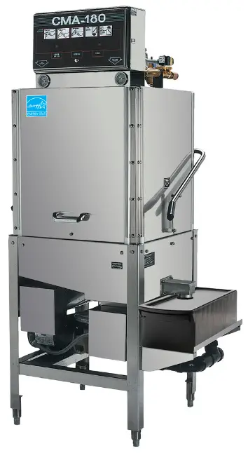
Parts Manual
1.1 Initial Parts Kit #1100.17
| P/N | DESCRIPTION | Qty |
| 00121.18 | CMA-180 Drain Stopper O-ring | 1 |
| 00200.10 | Pump Assy. 115/220V 60Hz (Open) | 1 |
| 00206.30 | Pump Seal Kit | 1 |
| 00304.29 | Rinse Arm w/ Bearings | 1 |
| 00307.20 | Spray Arm Assy CMA180 w/ bearing & end plugs | 1 |
| 00363.00 | Spray Base Pull Lock Pin | 1 |
| 00404.85 | Contactor 208/240V 20 Amp DP | 1 |
| 00411.00 | Micro Switch | 1 |
| 00421.78 | Illuminated Plug CMA-180/44 P | 1 |
| 00421.90 | Power Switch Red 250V | 1 |
| 00475.70 | Toggle Switch DPDT 15 Amp/Delimer | 1 |
| 00501.17 | Timer Motor Assy 60 Sec 220V/60Hz | 1 |
| 00562.00 | Roller Door Switch | 1 |
| 00602.00 | Door Spring | 1 |
| 00631.05 | Ice Cube Relay 220V 12 Amp | 1 |
| 00706.00 | 3/4 Water Solenoid Repair Kit JE | 1 |
| 00735.00 | 3/4 Vac Breaker Rep Kit Watts | 1 |
| 00738.15 | Solenoid Coil JE 220V (3/4 & 1/2) | 1 |
| 03202.00 | Thermometer (Capillary) | 1 |
| 03408.55 | Counter – Face Mount 220V/50Hz | 1 |
| 03470.00 | Toggle Switch (Momentary) Screw Term | 1 |
| 13003.17 | Contactor 60 Amp 3 Pole | 1 |
| 13003.55 | Contactor 30 Amp | 1 |
| 13304.55 | SS Final Rinse Spray Jet SS | 1 |
| 13417.92 | Heater Thermostat | 1 |
| 13422.71 | Immersion Heater 208-240V/12kW T-Flange | 1 |
| 13463.14 | Liquid Level Switch-Long-D Flat | 1 |
| 13605.00 | Pressure Gauge | 1 |
| 15518.00 | Immersion Heater 6kW208-240V T-Flange | 1 |
| 17523.51 | Hi Limit Switch 250 Deg | 1 |
1.2. Exploded View Drawings
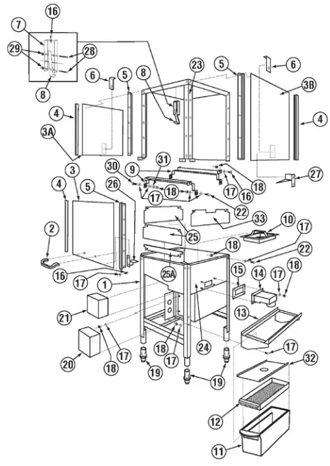
1.2.1. Straight Frame System Assembly
| ITEM NO. | NO. REQ’D | P/N | DESCRIPTION | ITEM NO. | NO. REQ’D | P/N | DESCRIPTION |
| 1 | 1 | 17532.00 | Stand | 18 | 30 | 00912.00 | ¼”-20 Nylon Lock Nut |
| 2 | 1 | 00535.30 | Front door Handle | 19 | 4 | 01310.00 | Bullet Feet |
| 3 | 3 | 17506.00 | Door | 20 | 1 | 17522.50 | Wash Tank Heater Cover |
| 4 | 6 | 00636.15 | E Z Door Glide | 21 | 1 | 17522.00 | Booster Heater Cover |
| 5 | 6 | 17554.00 | Door Guide | 22 | 23 | 00914.10 | 1/4-20 X 5/8 Hex Bolt |
| 6 | 2 | 17552.00 | Door Stop | 23 | 1 | 17530.00 | Wrapper |
| 7 | 1 | 13915.60 | Door Latch Bracket | 24 | 1 | 17531.17 | Pan |
| 8 | 1 | 13701.00 | Open Door Latch | 25 | 2 | 17506.60 | Door Panel Splash Guard |
| 9 | 1 | 01505.02 | Tray Track (Set) | 25A | 1 | 17506.65 | Door Service Splash Guard |
| 10 | 2 | 17510.00 | Strainer Basket | 26 | 1 | 17506.21 | Front Door Safety Bracket |
| 11 | 1 | 01577.10 | Scrap Tray Body | 27 | 1 | 17506.32 | Right Door Safety Bracket |
| 12 | 1 | 01577.21 | Scrap Trap Drawer | 28 | 1 | 00960.00 | 8-32×1-1/2”pPanhead Screw |
| 13 | 1 | 17579.00 | Scrap Trap Holder | 29 | 1 | 00927.00 | 8-32 Nylon Lock Nut |
| 14 | 1 | 17511.00 | Overflow | 30 | 2 | 00962.00 | 1/4-20 X 1 SS Hex Bolt |
| 15 | 1 | 17402.00 | Overflow Gasket | 31 | 4 | 00610.00 | Door Handle Spacer (Small) |
| 16 | 30 | 00905.00 | ¼-20 x 1/2 Trus Bolt | 32 | 1 | 01577.30 | S/S Scrap Trap Lid |
| 17 | 60 | 00924.00 | ¼” SS Washer | 33 | 1 | 17506.62 | 180 Splash Shield – lever side |
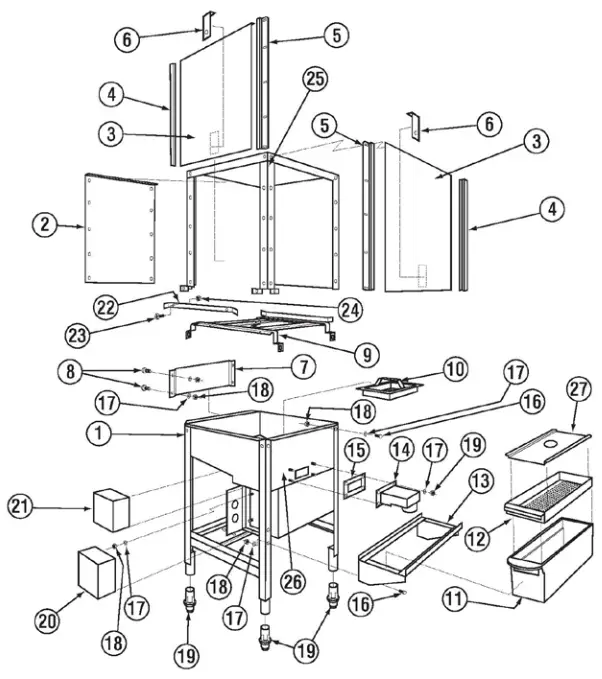
1.2.2. Corner Frame Assembly
| ITEM NO. | NO. REQ’D | P/N | DESCRIPTION | ITEM NO. | NO. REQ’D | P/N | DESCRIPTION |
| 1 | 1 | 17532.00 | Stand | 14 | 1 | 17511.00 | Overflow |
| 2 | 1 | 17506.50 | Door Panel Corner | 15 | 1 | 17402.00 | Overflow Gasket |
| 3 | 2 | 17506.00 | Door | 16 | 24 | 00906.00 | ¼”-20 x 1/2” Hex Head Bolt |
| 4 | 4 | 00636.15 | E Z Door Glide | 17 | 56 | 00924.00 | ¼” SS Washer |
| 5 | 4 | 17554.00 | Door Guide | 18 | 30 | 00912.00 | ¼”-20 Nylon Lock Nut |
| 6 | 2 | 17552.00 | Door Stop | 19 | 4 | 01310.00 | Bullet Feet |
| 7 | 1 | 17507.20 | Air Gap Baffle | 20 | 1 | 17522.50 | Wash Tank Heater Cover |
| 8 | 4 | 00905.00 | ¼” – 20 x ½ Truss Head Bolt | 21 | 1 | 17522.00 | Booster Heater Cover |
| 9 | 1 | 01505.10 | Tray Track | 22 | 1 | 01505.16 | Tray Track Rail |
| 10 | 2 | 17510.00 | Strainer Basket | 23 | 2 | 00941.00 | 8/32” x 5/8” Pan Head Screw |
| 11 | 1 | 01577.10 | Scrap Trap Body | 24 | 2 | 03801.00 | 10/32” Lock Nut |
| 12 | 1 | 01577.21 | Scrap Trap Drawer | 25 | 1 | 17530.00 | Wrapper |
| 13 | 1 | 17579.00 | Scrap Trap Holder | 26 | 1 | 17531.17 | Pan |
| 27 | 1 | 01577.30 | S/S Scrap Trap Lid | ||||
1.2.3. Drain System Assembly
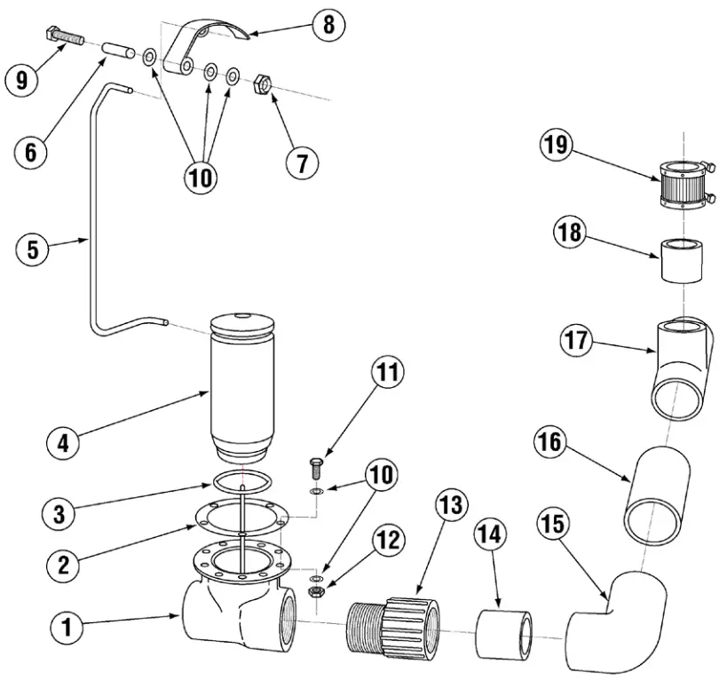
| ITEM NO. | NO. REQ’D | P/N | DESCRIPTION | ITEM NO. | NO. REQ’D | P/N | DESCRIPTION |
| 1 | 1 | 00113.17 | Drain Tee Casting | 11 | 6 | 00901.00 | 5/16 –18×1” Hex Head Bolt |
| 2 | 1 | 00114.00 | Drain Tee Gasket | 12 | 6 | 13805.00 | 5/16-18 Nylon Lock Nut |
| 3 | 1 | 00121.18 | Drain Stopper “O” Ring | 13 | 1 | 01313.00 | 2” PVC Slip x MIPT Adapter |
| *4 | 1 | 00121.17 | Drain Stopper (Incl O-Ring) | 14 | 1 | 05030.17 | 2” x 4” PVC Tubing |
| 5 | 1 | 17581.00 | Drain Linkage | 15 | 1 | 01312.00 | PVC Slip x Slip 90 Elbow |
| 6 | 1 | 17580.50 | Drain Linkage Spacer | 16 | 1 | 05030.27 | 2” x 6” PVC Tubing |
| 7 | 1 | 00912.00 | ¼-20 Nylon Lock Nut | 17 | 1 | 01320.17 | 2” PVC Tee |
| 8 | 1 | 17580.00 | Drain Lever | 18 | 1 | 05030.10 | 2” x 3” PVC Tubing |
| 9 | 1 | 00910.00 | ¼”-20×1 ½” Hex Head Bolt | 19 | 1 | 01315.17 | 2” No Hub |
| 10 | 16 | 00926.00 | 5/16 S/S Washer | ||||
*P/N 00121.17 includes P/N 00121.18
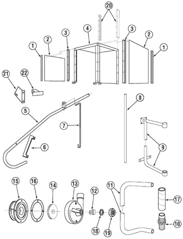
1.2.4. Plumbing System Assembly
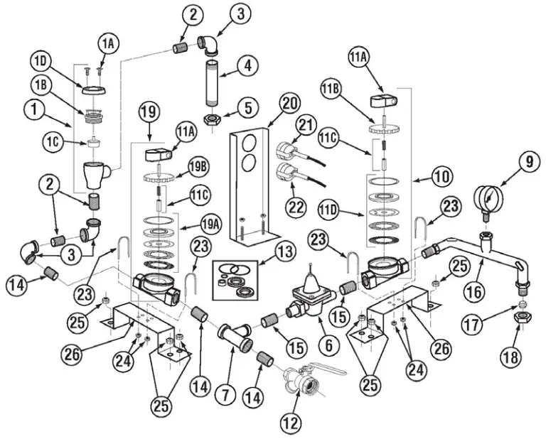
| ITEM NO. | NO. REQ’D | P/N | DESCRIPTION | ITEM NO. | NO. REQ’D | P/N | DESCRIPTION |
| 1 | 1 | 00710.50 | Vacuum Breaker ¾” Watts | 12 | 1 | 13029.00 | Strainer Ball Valve 3/4” |
| 1A | — | 00421.51 | Pan Head Screw SS 6-32 x 1/4” | 13 | — | 13028.00 | ¾” Ball Valve Repair Kit |
| 1B | — | 00735.60 | Vacuum Breaker Brass Bonnet | 14 | 2 | 13635.10 | Nipple Brass 2/4” x 2” |
| 1C | — | 00735.00 | Vacuum Breaker Repair Kit ¾” | 15 | 4 | 00742.00 | Nipple ½” x 1 ½” |
| 1D | — | 00739.50 | Vacuum Breaker Cap | 16 | 1 | 13607.50 | Final Rinse Plumbing |
| 2 | 3 | 13639.00 | Nipple SS ¾” Close | 17 | 1 | 00770.20 | 5/8 Compression Ftg. Ring |
| 3 | 3 | 13633.00 | Elbow FXF Brass ¾” | 18 | 1 | 00770.10 | 5/8 Compression Ftg. Nut |
| 4 | 1 | 13613.00 | Nipple ¾” x 5 ½” Brass | 19 | – | 00705.05 | Water Sol Valve ¾” 220V JE |
| 5 | 2 | 13606.10 | Jamb Nut Brass ¾” | 19A | – | 00706.00 | Water Sol Repair Kit JE ¾” |
| 6 | 1 | 13602.20 | Pressure Regulator ½” | 19B | – | 00705.20 | Water Sol Valve Bonnet ¾” |
| 7 | 1 | 00716.10 | Brass Tee ¾” x ¾” x ½” FXFXF | 20 | 1 | 17534.00 | 180 Thermometer Bracket |
| 8 | 1 | 13604.00 | Bushing ½” x ¼” Brass | 21 | 1 | 03202.00 | Thermometer “Wash” |
| 9 | 1 | 13605.00 | Pressure Gauge | 22 | 1 | 03202.18 | Thermometer “Rinse” |
| 10 | 1 | 03603.15 | Water Sol Valve 1/2” 220V JE-C | 23 | 4 | 01526.10 | Plumbing Bracket Strap |
| 11A | 1 | 00738.15 | Water Sol Valve Coil 220V | 24 | 4 | 00912.00 | 1/4-20 Nylon Lock Nut |
| 11B | — | 03603.20 | Water Sol Valve Bonnet ½” | 25 | 8 | 00912.00 | 1/4-20 Nylon Lock Nut |
| 11C | — | 00786.00 | Water Sol Plunger G Style | 26 | 2 | 01526.00 | Plumbing Support Bracket |
| 11D | — | 00707.00 | Water Sol Repair Kit JE ½” | ||||
1.2.5. Wash Spray System
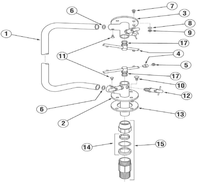
| ITEM NO. | NO. REQ’D | P/N | DESCRIPTION |
| 1 | 1 | 00303.17 | Manifold |
| *2 | 1 | 00360.24 | Lower Spray Base Assembly |
| **3 | 1 | 00361.10 | Upper Spray Base Assembly |
| 4 | 2 | 00304.17 | Wash Spray Arm |
| 5 | 4 | 00308.50 | Spray Arm End Plug SS |
| 6 | 2 | 00302.51 | Spray Base “O” Ring |
| 7 | 4 | 00905.00 | Truss Head Bolt ¼”-20”x1/2” |
| 8 | 12 | 00924.00 | SS Washer ¼” |
| 9 | 8 | 00912.00 | Nylon Lock Nut ¼” – 20 |
| 10 | 4 | 00914.10 | Hex Head Bolt ¼”-20”x5/8” |
| 11 | 2 | 00966.10 | Hex Head SS Bolt 10-32 |
| 12 | 4 | 00363.00 | Spray Base Lock Pin |
| 13 | 1 | 00302.00 | Spray Base Gasket |
| 14 | 1 | 00225.00 | Compression Gasket |
| 15 | 1 | 00221.20 | 1” Comp. Fit.x1”MIP SS |
| 16 | 1 | 00759.17 | Base Quick Release W/Nipple |
| 17 | 2 | 00341.00 | Spray Arm Bearing |
**P/N 00361.10 Includes Items 11,12 & 6
*P/N 00360.24 Includes Items 11, 12 & 6
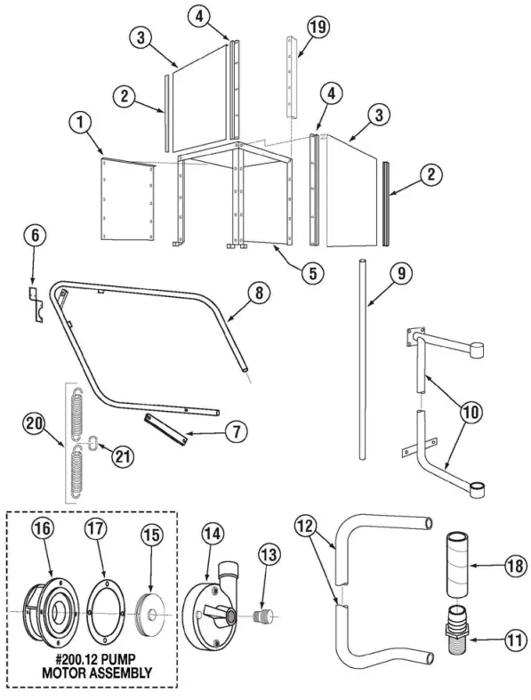
1.2.6. Final Rinse System
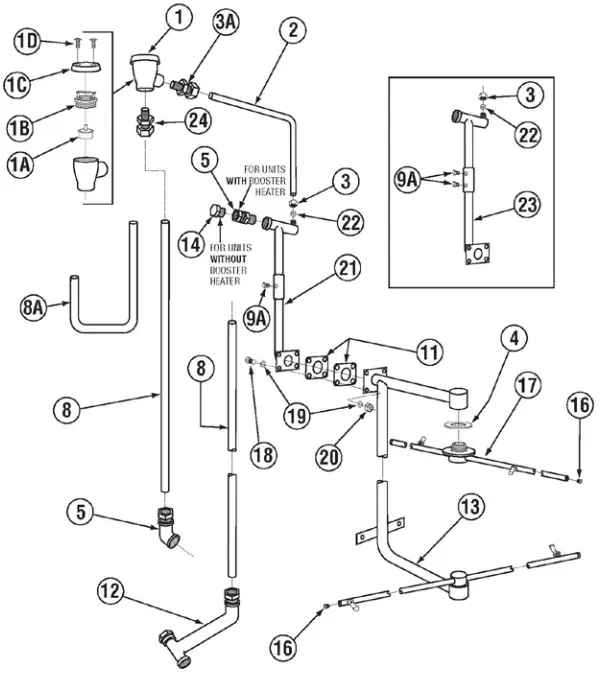
| ITEM NO. | NO. REQ’D | P/N | DESCRIPTION | ITEM NO. | NO. REQ’D | P/N | DESCRIPTION |
| 1 | 1 | 03624.00 | ½” Vacuum Breaker Watts | 10 | 1 | 13306.17 | Final Rinse Elbow Assy. |
| 1A | — | 03623.00 | ½” Vacuum Brkr Kit- Watts | 11 | 2 | 04306.00 | Square Manifold Gasket |
| 1B | — | 03624.25 | ½” Brass Bonnet | 12 | 1 | 17550.10 | Inlet Booster Heater Plumbing |
| 1C | — | 00739.50 | ¾” Vacuum Breaker Cap SS | 13 | 1 | 17401.00 | Final Rinse Manifold |
| 1D | — | 00421.51 | 6-32 x ¼” SS Pan Head Screw | 14 | 1 | 13642.00 | ½” Brass Plug |
| 2 | 1 | 05004.10 | 3/8” SS Tubing | 15 | 1 | 00743.10 | ½” Tee F x F x F |
| 3 | 1 | 13607.10 | 3/8” Comp x ½” MIP Elbow | 16 | 4 | 00308.17 | Rinse Arm SS End Plug |
| 3A | 1 | 00436.20 | Comp Fitting Nut | 17 | 2 | 00304.29 | Rinse Arm w/Bearing |
| 4 | 2 | 04305.17 | Bearing Gasket | 18 | 4 | 00929.00 | 1/4-20 X 3/4 Bolt |
| 5 | 1 | 17550.11 | Outlet Booster Heater Plumbing | 19 | 8 | 00926.00 | SS Washer 5/16” |
| 6 | 1 | 13629.00 | ½” S.S. Close Nipple | 20 | 4 | 00912.00 | ¼”-20 Nylon Lock Nut |
| 7 | 1 | 13629.82 | Nipple SS ½” x 5 ½” | 21 | 1 | 13607.00 | Water Inlet |
| 8 | 2 | 05007.17 | 5/8” OD .049 Wall Tubing | 22 | 1 | 13607.20 | Comp Fitting Sleve |
| 8A* | 1 | 00797.17 | Booster Heater Bypass Line | 23 | 1 | 13607.30 | Water Inlet L.T. |
| 9 | 1 | 13669.45 | Mixing Chamber SS | 24 | 1 | 00760.00 | 5/8 Comp x ½ MIP Adapter |
| 9A | 2 | 03232.00 | 1/8” Male Plug | ||||
*8A replace 8 only on the machines without booster heater.
1.2.7. CMA-180 Door Handle Assembly
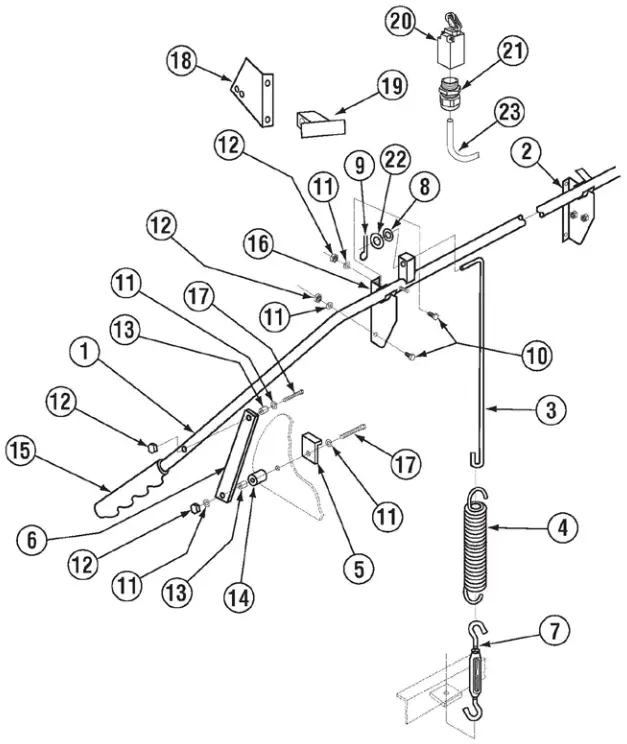
| ITEM NO. | NO. REQ’D | P/N | DESCRIPTION | ITEM NO. | NO. REQ’D | P/N | DESCRIPTION |
| 1 | 1 | 00613.32 | Door Handle | 13 | 4 | 00610.00 | Door Handle Spacer (Small) |
| 2 | 1 | 01556.50 | Right Door Handle Support | 14 | 4 | 00611.00 | Door Handle Spacer (Large) |
| 3 | 2 | 00603.07 | Door Spring Extension Rod | 15 | 2 | 00607.04 | Door Handle Cap |
| 4 | 2 | 00602.00 | Door Spring | 16 | 1 | 01555.50 | Left Door Handle Support |
| 5 | 2 | 17552.00 | Door Stop | 17 | 2 | 00910.00 | ¼”-20×1/2” Hex Head Bolt |
| 6 | 2 | 01553.00 | Door Handle Link | 18 | 1 | 00563.40 | Door Switch Bracket (8-08) |
| 7 | 2 | 00606.50 | Turn Buckle | 19 | 1 | 00563.42 | Door Switch Actuator (8-08) |
| 8 | 2 | 00926.00 | 5/16” SS Washer | 20 | 1 | 00562.00 | Door Roller Switch |
| 9 | 2 | 00900.00 | Cotter Pin | 21 | 1 | 00562.60 | Connector Door Roller Switch |
| 10 | 4 | 00906.00 | ¼”-20 x ½” Hex Head screw | 22 | 1 | 00605.30 | Door Rod Spacer |
| 11 | 8 | 00924.00 | ¼” SS Washer | 23 | 1 | 00546.00 | 18 AWG Switch Cord |
| 12 | 8 | 00912.00 | ¼”-20” Nylon Insert Lock Nut | ||||
1.2.8. Corner Door Handle Assembly
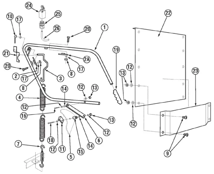
| ITEM NO. | NO. REQ’D | P/N | DESCRIPTION | ITEM NO. | NO. REQ’D | P/N | DESCRIPTION |
| 1 | 1 | 00613.04 | Door Handle | 14 | 4 | 00610.00 | Door Handle Spacer (St) |
| 2 | 1 | 00619.34 | Door Handle Mntg Plate Lg | 15 | 4 | 00611.00 | Door Handle Spacer (Lg) |
| 2A | 1 | 00619.44 | Door Handle Mntg Plate St | 16 | 2 | 00903.00 | ¼-20 x 1 ¾” Hex Head Bolt |
| 3 | 1 | 00603.04 | Door Spring Extension | 17 | 9 | 00926.00 | 5/16” SS Washer |
| 4 | 2 | 00602.00 | Door Spring | 18 | 2 | 00910.00 | ¼”-20×1/2” Hex Head Bolt |
| 5 | 2 | 17506.00 | Door | 19 | 2 | 00607.04 | Door Handle Cap |
| 6 | 2 | 01553.00 | Door Handle Link | 20 | 8 | 00920.00 | 5/16-18×3/4” Hex Head Bolt |
| 7 | 1 | 00606.50 | Turn Buckle | 21 | 1 | 00563.30 | Limit Switch Door Bracket |
| 8 | 9 | 00913.00 | 5/16”-18” Nut | 22 | 1 | 17506.50 | Door Panel Corner |
| 9 | 10 | 00905.00 | ¼”-20×1/2” Truss Head Bolt | 23 | 1 | 17507.20 | Air Gap Baffle Corner |
| 10 | 1 | 00900.00 | Cotter Pin | 24 | 1 | 00563.40 | Door Switch Bracket (8-08) |
| 11 | 2 | 01552.00 | Door Stop | 25 | 1 | 00562.60 | Connector Door Roller Switch |
| 12 | 16 | 00924.00 | ¼” SS Washer | 26 | 1 | 00546.00 | 18 AWG Switch Cord |
| 13 | 14 | 00912.00 | ¼-20 Nylon Lock Nut | ||||
1.2.9. Pump System Assembly
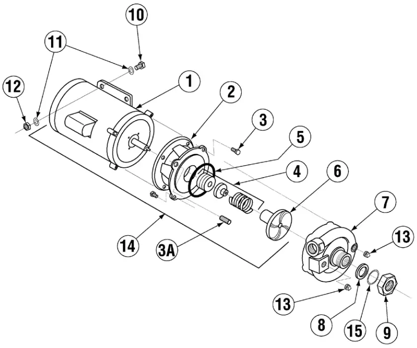
| ITEM NO. | NO. REQ’D | P/N | DESCRIPTION | ITEM NO. | NO. REQ’D | P/N | DESCRIPTION |
| 1 | 1 | 00201.00 00201.85 | Pump Motor 1 HP115/230V Pump Motor 1 HP230/460V | 8 | 1 | 00208.40 | Slip Joint Nut Gasket |
| 2 | 1 | 04207.10 | Small Pump Base | 9 | 1 | 04204.00 | Compression Nut (2.5) |
| 3 | 6 | 00921.00 | 3/8”-16 x 34” Hex Head Bolt | 10 | 2 | 00906.00 | ¼-20 x 1/2” Hex Bolt |
| 3A | 2 | 00975.00 | 3/8-16 x 1 ½” Stud | 11 | 2 | 00924.00 | ¼” SS Washer |
| 4 | 1 | 00206.30 | Pump Seal Kit | 12 | 2 | 00912.00 | ¼”-20 Nylon Lock Nut |
| 5 | 1 | 03226.00 | Pump “O” Ring | 13 | 2 | 00238.00 | 3/8” Male Plug |
| 6 | 1 | 03222.10 | Impeller SS | *14 | Assy. | 00200.10 | Pump Assy |
| 7 | 1 | 04207.20 | Pump Cover | 15 | 1 | 00208.21 | Slip Joint Nut Friction Ring |
*P/N 00200.85 Includes Items 1,2,3,4,5 and 6
1.2.10. Old Wash Tank Heater (Square Flange)
| ITEM NO. | NO. REQ’D | P/N | DESCRIPTION |
| 1 | 1 | 13417.65 | Wash Tank Heater 5KW 3PH |
| 1 | 13417.64 | Wash Tank Heater 7KW 3PH | |
| 1A | 1 | 13417.92 | Heater Thermostat |
| 2 | 1 | 13463.14 | Liquid Level Switch |
| 3 | 1 | 13463.50 | Liquid Level Switch Shield |
| 4 | 1 | 17523.51 | Hi-Limit Switch – Wash 250 Degrees |
| 5 | 1 | 13477.20 | 7/8” Probe Hole Plug |
| 6 | 1 | 13417.45 | Wash Tank Heater Gasket |
1.2.11. Old Booster Heater (Square Flange)
| ITEM NO. | NO. REQ’D | P/N | DESCRIPTION |
| 1 | 1 | 17550.00 | Booster Tank |
| 2 | 6 | 13805.00 | Nylon Lock Nut 5/6”-18 |
| 3 | 6 | 00926.00 | Washer SS 5/16” |
| **4 | 1 | 13417.67 | Immersion Heater 12KW 3PH |
| 4A | 1 | 13417.92 | Thermostat 12KW Heater |
| 5 | 1 | 17523.51 | Hi-Limit Switch-Booster 250 degrees |
| *6 | 1 | 17520.00 | Booster Heater Shield* |
| 7 | 1 | 13417.47 | Booster Heater Gasket |
| 8 | 1 | 17560.00 | Complete Assembly |
| 9 | 1 | 40116.00 | 1/4 Comp x 1/4 MIP Fitting |
| *For Straight Through Applications Only. **Includes Gasket #13417.47 | |||
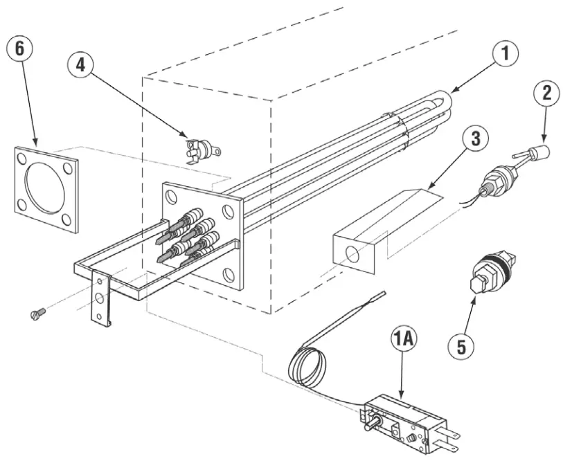
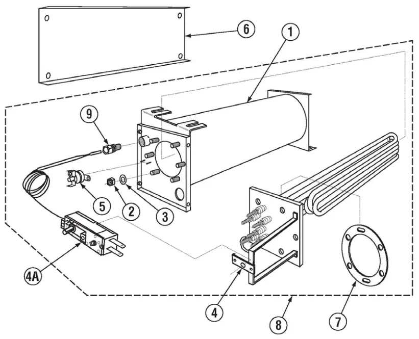
1.2.12. New Wash Tank Heater (Triangular Flange)
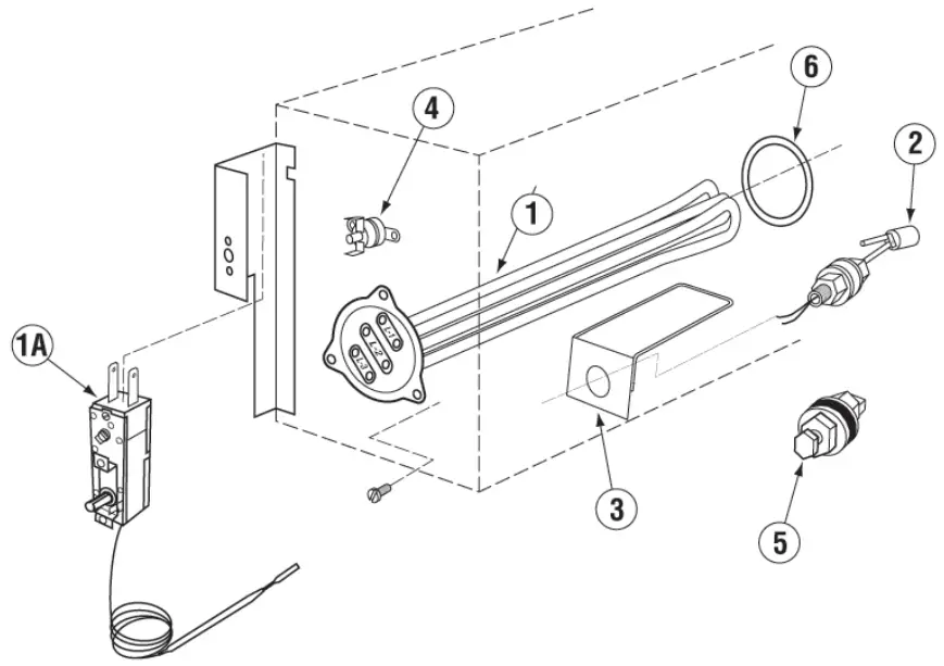
| ITEM NO. | NO. REQ’D | P/N | DESCRIPTION |
| 1 | 1 | 15518.00 13422.76 | Heater 6kW 220V Triangular Flange Heater 6kW 480V Triangular Flange |
| 1A | 1 | 13417.92 | Heater Thermostat |
| 2 | 1 | 13463.14 | Liquid Level Switch |
| 3 | 1 | 13463.51 | Liquid Level Switch Shield |
| 4 | 1 | 17523.51 | Hi-Limit Switch – Wash 250 Degrees |
| 5 | 1 | 13477.20 | 7/8” Probe Hole Plug |
| 6 | 1 | 15518.11 | Gasket for Triangular Flange Heater |
1.2.13. New Booster Heater (Triangular Flange)
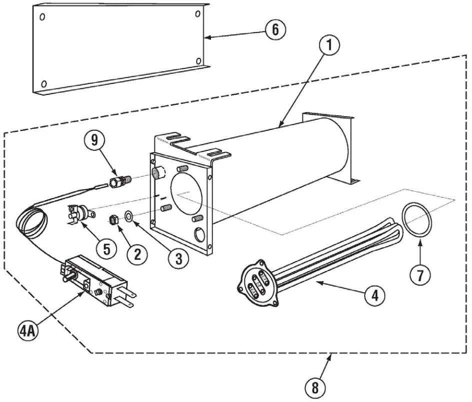
| ITEM NO. | NO. REQ’D | P/N | DESCRIPTION |
| 1 | 1 | 17550.20 | Booster Tank |
| 2 | 3 | 13805.00 | Nylon Lock Nut 5/6”-18 |
| 3 | 3 | 00926.00 | Washer SS 5/16” |
| 4 | 1 | 13422.71 13422.75 | 240V 12KW Triangular Immersion Htr 480V 12 kW Triangular Immersion Htr |
| 4A | 1 | 13417.92 | Thermostat 12KW Heater |
| 5 | 1 | 17523.51 | Hi-Limit Switch-Booster 250 degrees |
| *6 | 1 | 17520.00 | Booster Heater Shield* |
| 7 | 1 | 15518.11 | Gasket for Triangular Flange Heater |
| 8 | 1 | 17560.00 | Complete Assembly |
| 9 | 1 | 40116.00 | 1/4 Comp x 1/4 MIP Fitting |
1.2.14. 480 Control Box Assembly
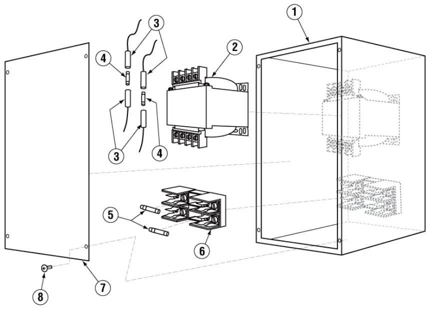
| ITEM NO. | NO. REQ’D | P/N | DESCRIPTION |
| 1 | 1 | 13905.13 | Transformer Box |
| 2 | 1 | 13423.82 | Transformer 480V – 240V |
| 3 | 2 | 13403.21 | Fuse Holder – Inline |
| 4 | 2 | 13403.40 | Fuse 1.25 Amp 230V Slow Blow |
| 5 | 2 | 13402.10 | Fuse 1.50 Amp 600V Slow Blow |
| 6 | 1 | 13420.10 | Fuse Clip 2-Poll, Pressure Plate |
| 7 | 1 | 13905.23 | Transformer Box Lid |
| 8 | 4 | 00940.50 | 10-32 3/8 Truss Head Screw |
1.2.15. Control Box Assembly
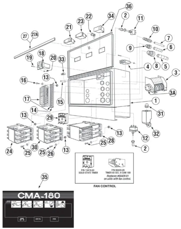
| ITEM NO. | NO. REQ’D | P/N | DESCRIPTION |
| 1 | 1 | 17503.39 | CMA-180 Control Box Body |
| 2 | 2 | 00470.10 | Toggle Switch Rubber Boot |
| 3 | 1* | 00409.81 | Timer CMA-180 |
| 3A | 1 | 00501.17 | Timer Motor |
| 4 | 1(2*) | 00631.05 | Ice Cube Relay 220V |
| 5 | 6 Ft. | 00400.85 | Conduit ¾” Sealtite |
| 6 | 6 Ft. | 00400.10 | Conduit ½” Sealtite |
| 7 | 2 Ft. | 00400.00 | Conduit 3/8” Sealtite |
| 8 | 1 | 00401.85 | St-3/4” Straight Connector |
| 9 | 1 | 00401.10 | St-1/2” Straight Connector |
| 10 | 1 | 00401.00 | St-3/8” Straight Connector |
| 11 | 1 | 00475.70 | Delimer Switch DPDT 15A |
| 12 | 1 | 03470.00 | Toggle Switch Momentary (Screw Terminal) |
| 13 | 8 | 03801.00 | Nylon Lock Nut 10-32 |
| 14 | 1 | 17400.06 | Mountain Din Rail |
| 15 | 1 | 13403.26 | Fuse 3A/250V Slow Blow |
| 16 | 2 | 00941.00 | Pan Head Screw 10 -32 x 5/8” |
| 17 | 1 | 17400.17 | Terminal Block Assembly |
| 17A | 2 | 17400.04 | 30 Amp Terminal Block-Red |
| 17B | 3 | 17400.03 | 60 Amp Terminal Block-Black |
| 17C | 4 | 17400.02 | 85 Amp Terminal Block-Natural |
| 17D | 2 | 17400.08 | 30 Amp Terminal Block-Blue |
| 17E | 2 | 17400.09 | 30 Amp Terminal Block-Natural |
| 17F | 1 | 17400.07 | 60 Amp Terminal Block-Green |
| 18 | 1 | 03408.55 | Counter Face Mount 220V |
| 19 | 4 | 00911.00 | Pan Head Screw 8-32 x 1/2” |
| 20 | 4 | 00927.00 | Lock Nut 8-32 |
| 21 | 1 | 00421.90 | Power Switch |
| 22 | 1 | 00449.50 | Keyless Lock |
| 23 | 1 | 00421.89 | Rocker Switch Auto Fill |
| 24 | 1 | 00404.85 | Motor Contactor 208/240V 20A |
| 13003.55 | Motor Contactor 30 Amp | ||
| 25 | 6 | 13825.00 | Pan Head Screw 8-31 x 1” |
| 26 | 6 | 04806.00 | #10 Brass Washer |
| 27 | 2 | 17503.17 | Control Box Sponge Long |
| 27A | 2 | 17503.18 | Control Box Sponge Short |
| 28 | 1** | 13003.17 | Contactor 60A 3 Pole 220V |
| 29 | 1 | 13418.60 | Dip Switch Timer 230V |
| 30 | 1 | 13003.55 | Heater Contactor 30 Amp |
| 31 | 1 | 00562.60 | Door Roller Switch Connector |
| 32 | 1 | 00562.00 | Door Roller Switch |
| 33 | 1 | 13426.50 | Ground Block |
| 34 | 1 | 00421.78 | Illuminated Plug |
| 35 | 1 | 006231.19 | Control Panel Label CMA-180 |
| 36 | 1 | 17503.29 | Control Box Lid |
* Includes timer motor p/n 501.17 and microswitch 411.00
** Only for the machines with booster heater
1.2.15. Control Box Assembly January 2021
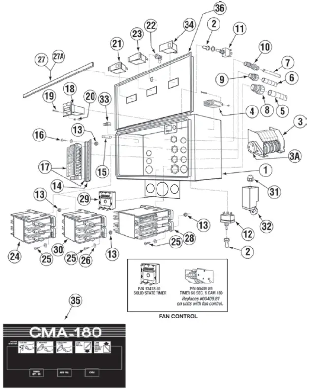
| ITEM NO. | NO. REQ’D | P/N | DESCRIPTION |
| 1 | 1 | 17503.39 | CMA-180 Control Box Body |
| 2 | 2 | 00470.10 | Toggle Switch Rubber Boot |
| 3 | 1* | 00409.81 | Timer CMA-180 |
| 3A | 1 | 00501.17 | Timer Motor |
| 4 | 1(2*) | 00631.05 | Ice Cube Relay 220V |
| 5 | 6 Ft. | 00400.85 | Conduit ¾” Sealtite |
| 6 | 6 Ft. | 00400.10 | Conduit ½” Sealtite |
| 7 | 2 Ft. | 00400.00 | Conduit 3/8” Sealtite |
| 8 | 1 | 00401.85 | St-3/4” Straight Connector |
| 9 | 1 | 00401.10 | St-1/2” Straight Connector |
| 10 | 1 | 00401.00 | St-3/8” Straight Connector |
| 11 | 1 | 00475.70 | Delimer Switch DPDT 15A |
| 12 | 1 | 03470.00 | Toggle Switch Momentary (Screw Terminal) |
| 13 | 8 | 03801.00 | Nylon Lock Nut 10-32 |
| 14 | 1 | 17400.06 | Mountain Din Rail |
| 15 | 1 | 13403.26 | Fuse 3A/250V Slow Blow |
| 16 | 2 | 00941.00 | Pan Head Screw 10 -32 x 5/8” |
| 17 | 1 | 17400.17 | Terminal Block Assembly |
| 17A | 2 | 17400.04 | 30 Amp Terminal Block-Red |
| 17B | 3 | 17400.03 | 60 Amp Terminal Block-Black |
| 17C | 4 | 17400.02 | 85 Amp Terminal Block-Natural |
| 17D | 2 | 17400.08 | 30 Amp Terminal Block-Blue |
| 17E | 2 | 17400.09 | 30 Amp Terminal Block-Natural |
| 17F | 1 | 17400.07 | 60 Amp Terminal Block-Green |
| 18 | 1 | 03408.55 | Counter Face Mount 220V |
| 19 | 4 | 00911.00 | Pan Head Screw 8-32 x 1/2” |
| 20 | 4 | 00927.00 | Lock Nut 8-32 |
| 21 | 1 | 00421.90 | Power Switch |
| 22 | 1 | 00449.50 | Keyless Lock |
| 23 | 1 | 00421.89 | Rocker Switch Auto Fill |
| 24 | 1 | 00404.85 | Motor Contactor 208/240V 20A |
| 13003.55 | Motor Contactor 30 Amp | ||
| 25 | 6 | 13825.00 | Pan Head Screw 8-31 x 1” |
| 26 | 6 | 04806.00 | #10 Brass Washer |
| 27 | 2 | 17503.17 | Control Box Sponge Long |
| 27A | 2 | 17503.18 | Control Box Sponge Short |
| 28 | 1** | 13003.17 | Contactor 60A 3 Pole 220V |
| 29 | 1 | 13418.60 | Dip Switch Timer 230V |
| 30 | 1 | 13003.55 | Heater Contactor 30 Amp |
| 31 | 1 | 00562.60 | Door Roller Switch Connector |
| 32 | 1 | 00562.00 | Door Roller Switch |
| 33 | 1 | 13426.50 | Ground Block |
| 34 | 1 | 00421.78 | Illuminated Plug |
| 35 | 1 | 006231.19 | Control Panel Label CMA-180 |
| 36 | 1 | 17503.29 | Control Box Lid |
* Includes timer motor p/n 501.17 and microswitch 411.00
** Only for the machines with booster heater
1.2.16. Unique Parts For CMA-180TS
| ITEM NO. | NO. REQ’D | P/N | DESCRIPTION | ITEM NO. | NO. REQ’D | P/N | DESCRIPTION |
| 1 | 6 | 00636.27 | Door Guide Material | 13 | 1 | 00204.00 | Pump Cover Large |
| 2 | 3 | 17506.20 | Scullery Door | 14 | 1 | 00203.05 | Impeller 4-1/2” |
| 3 | 6 | 17554.20 | Scullery Door Guide | 15 | 1 | 00202.00 | Pump Base |
| 4 | 1 | 17530.20 | Scullery Wrapper | 16 | 1 | 00205.00 | Pump Gasket |
| 5 | 1 | 00613.27 | Door Handle Straight | 17 | 1 | 03108.60 | Transfer Hose 1″ Reinf. |
| 6 | 2 | 01553.22 | Door Handle Link Straight | 18 | 1 | 00208.40 | Slip Joint Nut O Ring |
| 7 | 2 | 00603.53 | Door Spring Extension Rod | 19 | 1 | 00207.00 | Slip Joint Nut 11/2 x 1/4 |
| 8 | 2 | 05007.27 | Booster Water Line | 20 | 1 1 | 17570.00 17570.10 | Wrap Support Brkt-R Wrap Support Brkt-L |
| 9 | 1 | 17401.20 | Final Rinse Manifold | 21 | 1 | 00563.40 | Door Switch Bracket (8-08) |
| 10 | 1 | 50302.10 | 1″ MPT x 1″ Barb Brass | 22 | 1 | 00563.43 | Door Switch Actuator CMA- 180T (1-10) |
| 11 | 1 | 00303.27 | Manifold | 23 | 2 | 00602.20 | Door Spring – Heavy Duty |
| 12 | 1 | 00212.50 | 1-1/2”x1-1/4”Adapter | ||||
1.2.17. Unique Parts For CMA-180TC
| ITEM NO. | NO. REQ’D | P/N | DESCRIPTION | ITEM NO. | NO. REQ’D | P/N | DESCRIPTION |
| 1 | 1 | 17506.20 | Door Panel Scullery Corner | 12 | 1 | 00303.27 | Manifold |
| 2 | 6 | 00636.27 | Door Guide Material | 13 | 1 | 00212.50 | 1-1/2”x1-1/4”Adapter |
| 3 | 2 | 17506.20 | Scullery Door | 14 | 1 | 00204.00 | Pump Cover Large |
| 4 | 4 | 17554.20 | Scullery Door Guide | 15 | 1 | 00203.05 | Impeller 4-1/2” |
| 5 | 1 | 17530.20 | Scullery Wrapper | 16 | 1 | 00202.00 | Pump Base |
| 6 | 1 | 00563.60 | Limit Switch Door Bracket | 17 | 1 | 00205.00 | Pump Gasket |
| 7 | 2 | 01553.20 | Door Handle Link Corner | 18 | 1 | 03108.60 | Transfer Hose 1″ Reinf. |
| 8 | 1 | 00613.34 | Door Handle Corner | 19 | 1 | 17570.00 | Wrap Support Brkt-R |
| 9 | 2 | 05007.27 | Booster Water Line | 20 | 2 | 00602.20 | Door Spring – Heavy Duty |
| 10 | 1 | 17401.20 | Final Rinse Manifold | 21 | 1 | 00604.27 | Door Extension Link |
| 11 | 1 | 50302.10 | 1″ MPT x 1″ Barb Brass | ||||
1.2.18. Unique Parts for CMA-180T Split Door
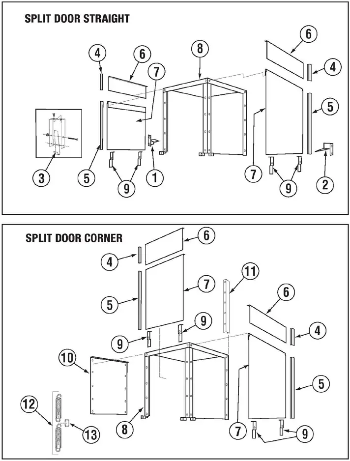
| ITEM NO. | NO. STR/COR | P/N | DESCRIPTION | ITEM NO. | NO. STR/COR | P/N | DESCRIPTION |
| 1 | 1/0 | 17506.23 | Door Safety Brkt. Left | 8 | 1/1 | 17530.22 | Wrapper |
| 2 | 1/0 | 17506.24 | Door Safety Brkt. Right | 9 | 6/4 | 17552.22 | Door Stop |
| 3 | 1/0 | 13701.22 | Open Door Latch | 10 | 0/1 | 17530.23 | Corner Panel Wrap |
| 4 | 6/4 | 00636.43 | EZ Glide Door Gide 8.5” | 11 | 1/1 1/0 | 17570.00 17570.10 | Wrap Support Brkt-R Wrap Support Brkt-L |
| 5 | 6/4 | 00636.42 | EZ Glide Door Gide 29.75” | 12 | 2 | 00602.20 | Door Spring – Heavy Duty |
| 6 | 3/2 | 17506.42 | Small Door | 13 | 1 | 00604.27 | Door Extension Link |
| 7 | 3/2 | 17506.34 | Large Door | ||||
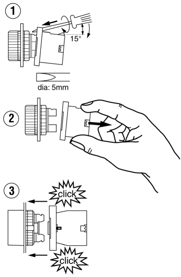
Power Switch Bulb Replacement Instructions
NOTE: For Old Style Machines ONLY — Manufactured prior to May 2002
TO REPLACE BULB
- Using a 5mm-screw driver dismount the light module from the actuator as shown in illustration 1 & 2.
- Replace the burnt bulb with a new one P/N 17421.10 by twisting the bulb 90 degrees.
- Mount the light module by snapping it onto the actuator as shown in illustration 3.

180 Conversion Kit – Corner to Straight #00617.18
INSTRUCTIONS:
- Open dishmachine doors to their highest position so that there is little spring resistance on the door handle. Remove hardware holding the door handle to the door linkage. Save all the washers and spacers. With the door handle in “UP” position, lift spring and remove from extension rod. Remove the nut attaching the eyebolt and save all hardware.
- To remove the door handle, simply unscrew the four bolts holding the door handle mounting plates and slide the complete assembly up and off of the cabinet. Use the bolts, nuts and washers to plug the holes in the back of the cabinet.
- Remove door panel & hardware from left side of machine, and install door guides from kit. Remove front door and relocate to left side of machine. The service door will be used to seal off this side of machine. Remove bolt located on top right hand corner of the wrapper and use it to mount service door latch bracket. Relocate tray track guide to front service door side of tray track.
- Using provided nuts, bolts and washers; mount the left and right door handle supports on the back of the cabinet. Insert the eyebolts into the brackets on the back of the dishmachine stand and screw the nuts on just enough to hold them in place. Hook both door springs and door spring extension rods on to the door handle and secure them with the washers and cotter pins. Then simply rest the door handle on the door handle supports. (You may have to lift the door handle to reach the handle supports.)
- Swing the door handle downwards to reach the door linkages; and using the two provided bolts and existing washers and spacers, attach the door linkages to the door handle. Adjust the tension in the spring by tightening the nuts under the eyebolt bracket so that the doors can slide up and down freely. Mount the provided door handle grips on the ends of the door handle.
- Eyebolt adjustment nuts should be adjusted to the point the doors begin to lift from a closed position. Both eyebolts should be adjusted the same. SEE “Illustration #1” for the proper location of all door handle hardware for CMA 180-S.
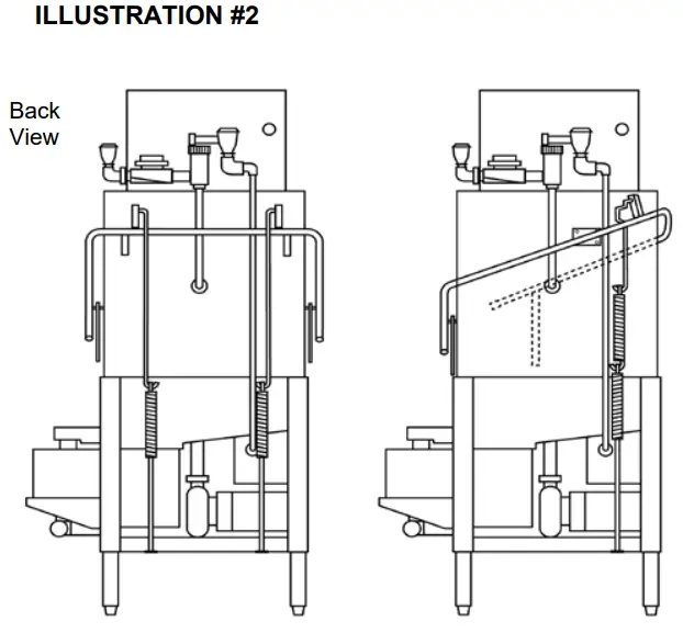
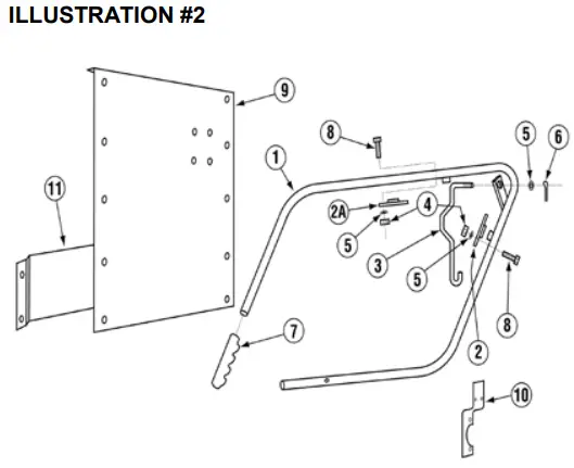
- “Illustration #2” shows CMA 180-S and CMA 180-C door handle assembly.
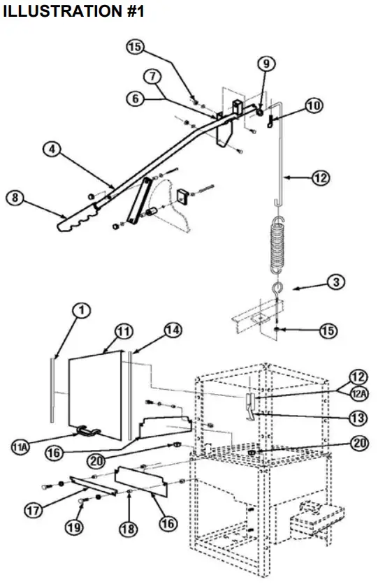 |  |
| ITEM NO. | NO. REQ’D | P/N | DESCRIPTION |
| 1 | 2 | 00636.17 | EZ Glide Door Guide |
| 2 | 2 | 00603.07 | Door Spring Extension Rod |
| 3 | 1 | 00606.00 | 5/16-18 x 7” Eyebolt |
| 4 | 1 | 00613.17 | Door Handle |
| 5 | 2 | 00913.00 | 5/16”-18 SS Nut |
| 6 | 1 | 01555.50 | L.H. Door Handle Support |
| 7 | 1 | 01556.50 | R.H. Door Handle Support |
| 8 | 2 | 00607.04 | Door Handle Grip |
| 9 | 4 | 00924.00 | ¼” SS Washer |
| 10 | 2 | 00900.00 | Cotter Pin |
| 11 | 1 | 17506.00 | Service Door |
| 11A | 1 | 00535.30 | Door Handle |
| 12 | 1 | 13915.00 | Door Latch Bracket |
| 12A | 1 | 13915.06 | Latch Bracket with Nut |
| 13 | 1 | 13701.00 | Open Door Latch |
| 14 | 2 | 17554.00 | Door Glide |
| 15 | 4 | 00912.00 | ¼” 20 Nylon Lock Nut |
| 16 | 2 | 17506.60 | Door Splashguard-Straight |
| 17 | 1 | 17506.65 | Service Door Splashguard-S |
| 18 | 4 | 00610.00 | Spacer Small |
| 19 | 4 | 00962.00 | ¼”-20 x 1 SS Hex Head Bolt |
| 20 | 2 | 1222.50 | Tank Plug |
180 Conversion Kit – Straight to Corner #00617.17
INSTRUCTIONS:
- Open dishmachine door to its highest position so that there is little spring resistance on the door handle. Remove hardware that holds the door handle to the door linkage. Save all the washers and spacers. Swing the door handle towards the back of the dishmachine and dismount it from the door handle support brackets. Remove the two nuts attaching the eyebolts and save the door springs.
- Remove the two (2) door-handle support brackets on the back of the cabinet and plug the four holes with original hardware. Remove front door and replace with left door. Remove door guides on left side of machine and attaché item No. 9 door panel-cover. The left door will now be at the front of the machine. Remove and relocate service door splashguard to left side of machine. Remove door latch for service door. The door latch is not needed on the CMA 180-C.
- With left door facing the front, door panel on the left, and service door splashguard in place, we are now ready to install the door handle.
- Using provided door handle, door handle mounting plates, 5/16” bolts, nuts and washers; install the door handle as shown in “Illustration #1”. Match the mounting plate holes to the cabinet holes and insert all bolts to ensure that the door handle and mounting plates are aligned. Then secure the mounting plate with nuts and washers.
Note: You may install one of the mounting plates first, then insert the door handle pivot post in and mount the other mounting plate last. - Attach the provided extension rod to the back of the door handle. Attach one eyebolt to the frame with existing hardware, along with two springs together. Pivot the door handle, positioning handle straight up. You may now connect loop of 2 nd spring to the door extension rod. Pull handles forward and down and attach to the door links.
- Adjust the nut on the eyebolt until the doors begin to lift then back off two turns. See “Illustration #2” for proper location of all door handle hardware included on CMA 180C.
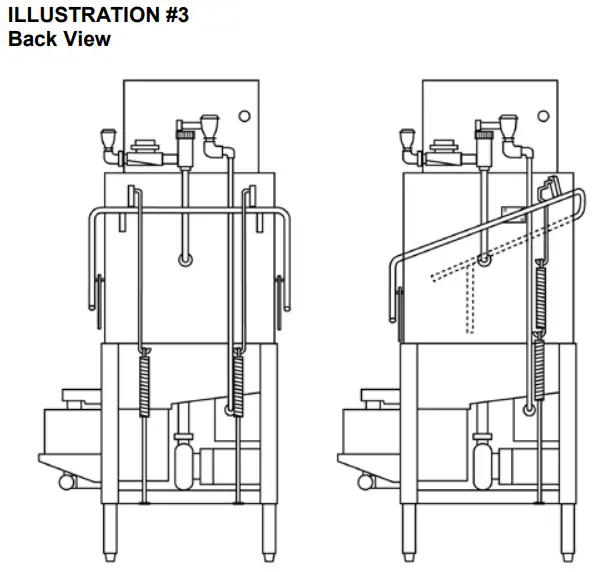
- “Illustration #3” shows CMA 180-S and CMA 180-C “Door Handle Assembly”.
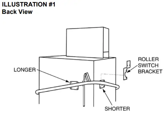
Note: Door handle mounting plates come in two sizes. Longer is mounted on back-right side.
| ITEM NO. | NO. REQ’D | P/N | DESCRIPTION |
| 1 | 1 | 00613.04 | Door Handle |
| 2 | 1 | 00619.34 | Door Hdl. Mtng. Plate-Long |
| 2A | 1 | 00619.44 | Door Hdl. Mtng. Plate-Short |
| 3 | 1 | 00603.04 | Door Spring Extension |
| 4 | 9 | 00913.00 | 5/16” – 18” Nut |
| 5 | 9 | 00926.00 | 5/16” SS washer |
| 6 | 1 | 00900.00 | Cotter Pin |
| 7 | 2 | 00607.04 | Door Handle Grip |
| 8 | 8 | 00920.00 | 5/16”-18 x ¾” Hex Head Bolt |
| 9 | 1 | 17506.50 | Door Panel-Cover |
| 10 | 1 | 00563.20 | Roller Switch Bracket |
| 11 | 1 | 17507.10 | Air Gap Baffle CMA 180C |
![]() CMA DISHMACHINES
CMA DISHMACHINES
12700 KNOTT AVENUE
GARDEN GROVE, CALIFORNIA 92841
800- 854- 6417
FAX 714-895-2141
www.cmadishmachines.com
Buy Parts![]() Rev. 2.09
Rev. 2.09


