Nova Electronics NOVA77GB-C Pro 77GHz Millimeter-WaveRadar
| Prepared by | Itachi.Wang | 2021.6.17 |
| Checked by | Mack.Zhong | 2021.6.18 |
| Approved by | Kevin.Li | 2021.6.19 |
Version history
| Version | Modify the description | Modified by | Data |
| V1.0 | Documentation initial release | Itachi.Wang | 2021.6.17 |
Overview
When driving a vehicle equipped with NOVA77GB-C Pro Lane Change Assist System to change lanes, the system can issue corresponding warnings to avoid accidents. The system complements the view of the mirrors inside and outside the car, and is not intended to completely replace the mirrors. When the driver wants to change lanes, the system’s millimeter-wave radar will sense the driving environment and warn the driver if it is not recommended to change lanes.
Mechanical and interface definitions
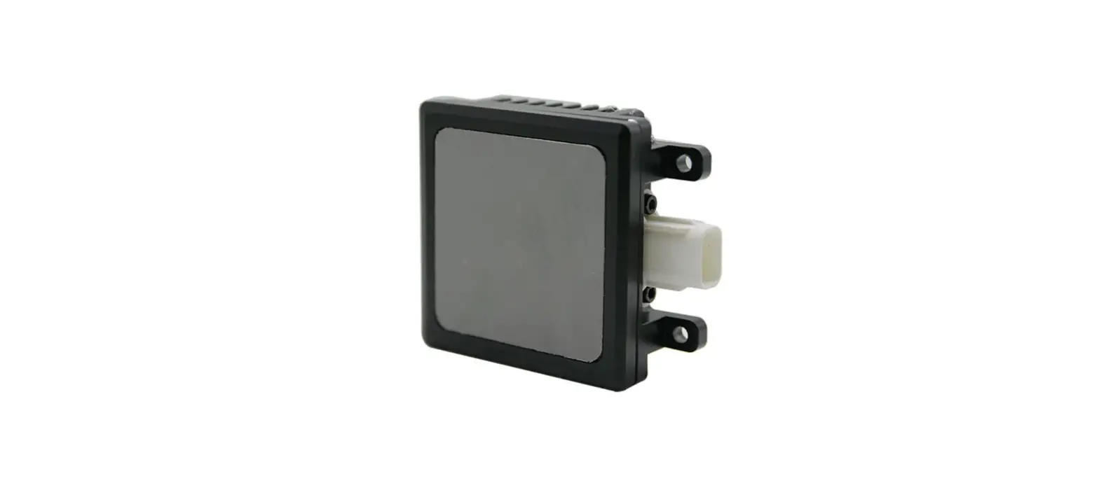
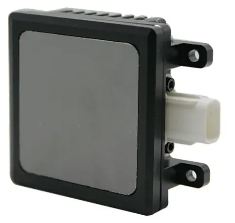
Product picture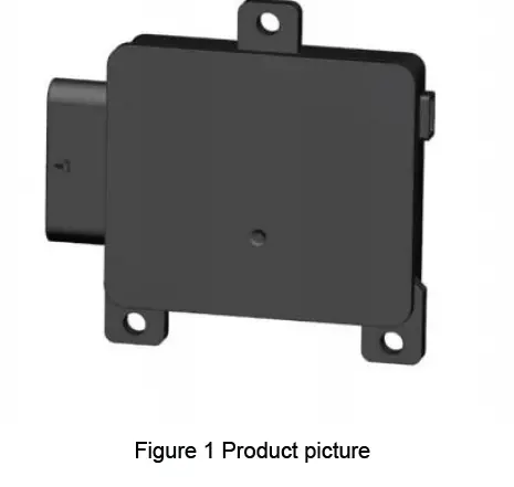
Definition of Hardware interfaces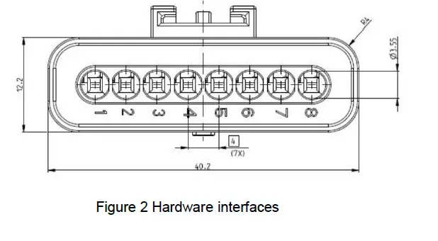
|
PIN No. | functional
description |
maximum current |
Signal types |
Description |
| 1 | KL31 | NC | power | Sensor ground: connected to KL31 |
| 2 | CAN1_H | NC | signal | |
| 3 | CAN1_L | NC | signal | |
|
4 |
KL15/NC |
NC |
power | Wake up source or
NC |
| 5 | CAN2_H | NC | signal | |
| 6 | CAN2_L | NC | signal | |
| 7 | LED_POWER_OUT | NC | power | LED Driver |
| 8 | KL30 | NC | power | Supply voltage for sensor connected to KL30(/KL15) |
Installation Instructions
Installation Instructions
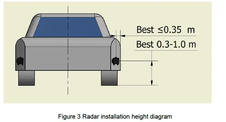
Installation height
The NOVA corner radar is recommended to be installed inside the rear bumper. The specific location requirements are as follows (see Figure 3 below):
- Installation height range for best performance: 0.3m—1.0m;
- Installation width range for best performance: within 0.35m from the side of the vehicle body.

Installation angle
- NOVA corner radar should be installed at both ends of the vehicle side and rear.
- Figure 4 below is a schematic diagram of the two-dimensional installation horizontal angle.
- Figure 5 below is a schematic diagram of the installation pitch angle.


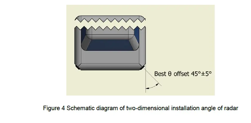
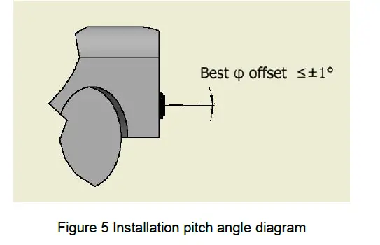
Figure 4 Schematic diagram of two-dimensional installation angle of radar
Installation error
The installation error of NOVA corner radar must meet the requirements of the following table to ensure the accuracy of radar detection angle and make the radar work normally. When calibrating the radar installation angle, the vehicle must stay on a horizontal plane to avoid tilting the body.
|
Angle installation error | Horizontal angle error: ±5° |
| Vertical angle error: ±1° |
Bumper or Obstruction Restrictions
Basic requirements
Ideal situation: The radar beam covers the direction without any metal parts or painted bumpers.
General situation: The corner radar is usually installed in the bumper at the rear of the vehicle, so special attention should be paid to the material selection, shape design, paint and relative position of the bumper or cover. At the same time, water droplets, water film and snow accumulation on the surface of the occluder may cause additional signal attenuation and further lead to limited performance and functionality.
Bumper Material Requirements
There should be no obstructions (including bumpers) in front of the radar. If the obstructions or bumpers are unavoidable, the materials of the obstructions must have a small dielectric constant and dielectric loss. These materials include Polypropylene, Polyamide, Polycarbonate, ABS (Acrylnitril-Butadien-Styrol), PC-PBT (Polycarbonate Type), etc. These materials should reduce the use of metal and carbon fiber, and the surface of the material should not contain metal or metal material coatings. The following table shows the material parameters of commonly used bumpers or coverings.
|
Material |
Dielectric constant | Best thickness 1 (mm) | Best thickness 2 (mm) | Best thickness 3 (mm) | Loss (dB); 77GHz, optimal thickness 2 |
| Polypropylene | 2.35 | 1.28 | 2.55 | 3.83 | 0.10 |
| Polyamide | 2.75 | 1.18 | 2.36 | 3.54 | 0.30 |
| Polycarbonate | 2.8 | 1.16 | 2.33 | 3.49 | 0.17 |
| ABS | 3.12 | 1.10 | 2.21 | 3.31 | 0.30 |
Bumper Thickness Requirements
In order to ensure that the radar achieves high conductivity, the thickness of the bumper needs to be selected carefully. Among the above mentioned materials,the thickness of the bumper should be an integer multiple of half the wavelength of the 77GHz millimeter-wave radar. Such as ABS material bumper thick the degree should be n*1.2mm (in the 77GHz range, n=1, 2, …). Attenuation increases with bumper thickness increase and increase.
In order to prevent the radar beam from being distorted, the bumper should be kept as flat as possible, and the thickness should be uniform,any slight bend can have a big impact on the radar beam.
Bumper shape requirements
The surface of the bumper or shield must be smooth (roughness should be less than one-tenth of a wavelength, about 400 microns), uniform in thickness, and its radius of curvature should be as large as possible (small curvature) to reduce distortion and attenuation of the radar beam . Figure 8 shows the influence of the shape of the bumper on the radar performance, from left to right are bumper digging (completely unobstructed), parallel, small curvature, thickness gradient, and sharp edge.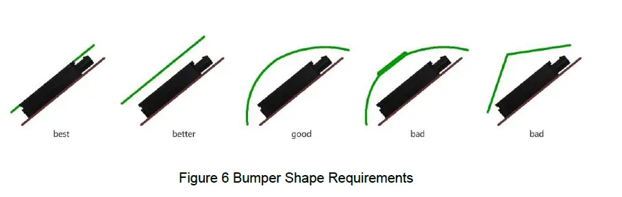
Certified Product & Warnings
Please take attention that changes or modification not expressly approved by the party responsible for compliance could void the user’s authority to operate the equipment.
This device complies with Part 15 of the FCC Rules. Operation is subject to the following two conditions:
- This device may not cause harmful interference, and
- This device must accept any interference received, including interference that may cause undesired operation.
This device complies with Industry Canada licence-exempt RSS standard(s). Operation is subject to the following two conditions:
- this device may not cause interference, and
- this device must accept any interference, including interference that may cause undesired operation of the device.
This equipment complies with FCC/IC RSS-102 radiation exposure limits set forth for an uncontrolled environment. This equipment should be installed and operated with minimum distance 20cm between the radiator & your body.
§ 95.393 Instructions and warnings
- Instructions concerning all controls, adjustments and switches that may be operated or adjusted without resulting in a violation of FCC rules;
- Warnings concerning any adjustment that could result in a violation of FCC rules or that is recommended to be performed only by or under the immediate supervision and responsibility of aperson certified as technically qualified to perform transmitter maintenance and repair duties in the relevant radio service by an organization or committee representative of users of that service;
- Warnings concerning the replacement of any transmitter component (crystal, semiconductor, et that could result in a violation of FCC rules; and
- For a transmitter that can only be operated with an FCC license, warnings concerning complia with applicable licensing requirements and information concerning license application procedures.
File No:R-JS-AS-13 |
Version:V1.0


