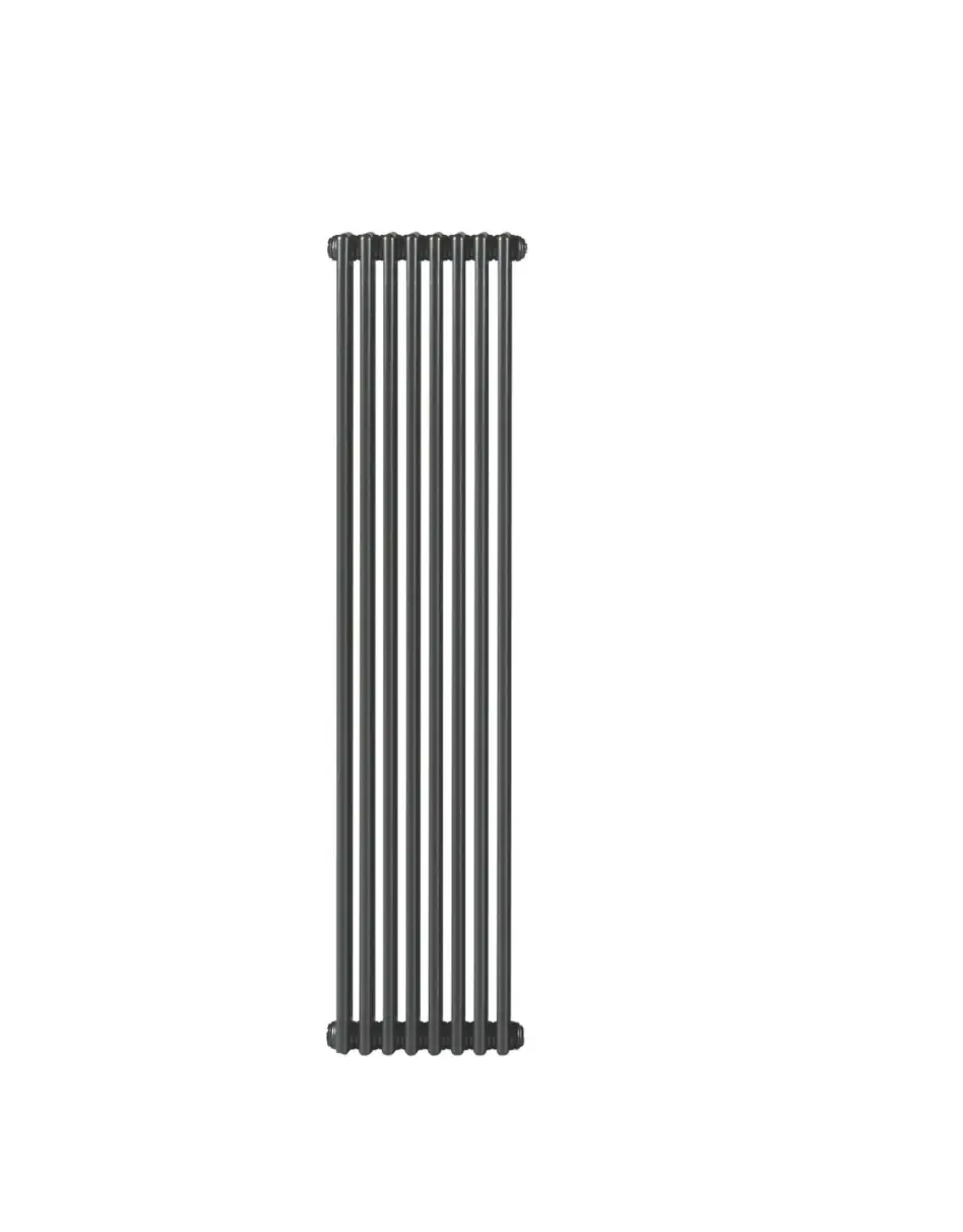
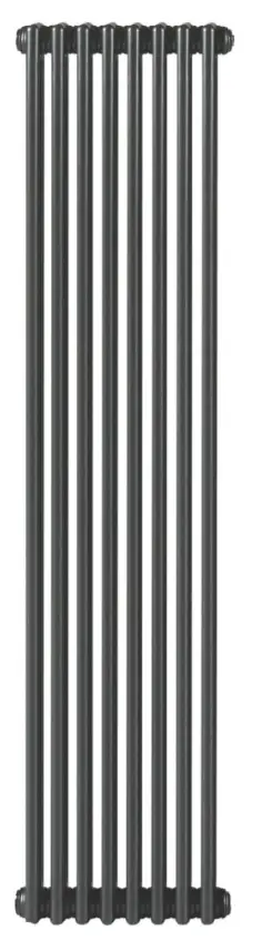
ACOVA 4629BTU 2000 x 398mm Classic 4 Column Radiator
This manual is a guide to the installation and maintenance of this column radiator.
Please register within 30 days in order to qualify for your warranty. The radiator must be installed in accordance with BS7593 and to the recognised water treatment procedures and standards. Failure to correctly dose the heating circuit can cause the radiator to corrode immediately and will negate the warranty.
The system should be tested with the annual service and details can be entered on this document. All images and details contained are subject to change and should be checked before installation.
Assembly Instructions
Sufficient PTFE tape must be applied to valve-tail threads prior to their installation. Silicone thread sealant should be applied to all threaded components manufactured with ‘O-rings’.
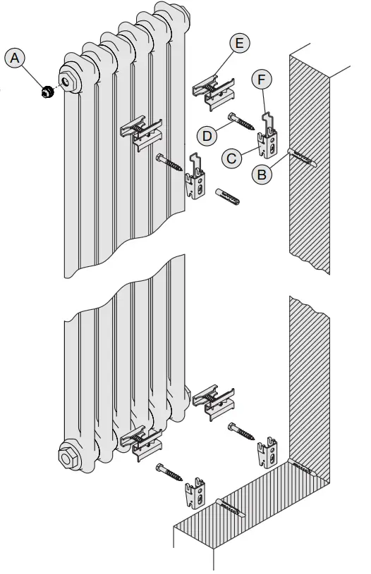
- Fit valve tails, using correct size Allen key. Accurately mark out bracket holes on wall.
Drill 10mm diameter holes in wall to a minimum depth of 65mm and insert wall plugs (B). - Attach brackets (C) to wall with screws (D) as shown and level. Tightly fix the radiator tubes into the upper clamp assemblies (E). Loosely fit the lower clamp assemblies (E) to the radiator.
- Lift the radiator on to the wall and locate the upper clamp assemblies (E) into the slots in the upper brackets (B).
- Slide the lower clamp assemblies (E) until they locate in the slots in the lower brackets (B) and tighten clamps.
- Fix security clip (F) into position over upper clamps (E). Security clips must always be placed in the top left and top right brackets when mounting the radiator.
- Due to the unique flow diverter built within all column radiators the flow MUST be on the same side as the permanent blank which is diagonally opposite to the air vent bleed valve.
This radiator should be installed onto a central heating system that has been cleaned/flushed and contains water treatment and inhibitors in accordance with BS7593.
| Key | Component | Quantity |
| A | Air Vent – 1/2” (factory fitted) | 1 |
| B | Wall Plug* | 4 |
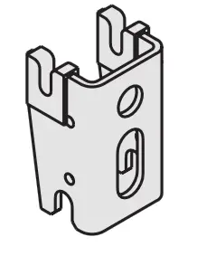
| C | Bracket | 4 |
| D | Screw – Hex Head* | 4 |
| E | Clamp Assembly | 4 |
| F | Security Clip | 2 |
* Wall plugs and screws not supplied
| Clamp Assembly (E) | Security Clip (F) | Bracket (C) |
| 4 x BH Height up to 1.5m, max 20 sections 1.5m+, max 10 sections | 2 x | 4 x CVD |
| 6 x BH Height up to 1.5m, >20 sections 1.5m+, >10 sections | 2 x | 6 x CVD |
 |  |  |
Tools & Material Required
Wall plugs – 10mm
Screws – 7mm diameter x 60mm length
Suitable valves
PTFE tape
Silicone thread sealant
Tape measure
Allen key – 13mm – 14mm
Socket driver – 10mm long reach
Electric drill
Masonry drill bit – 10mm diameter Spirit level
Scan this QR Code to register your warranty.
Dimensions, Bracket and Security Clip Positions
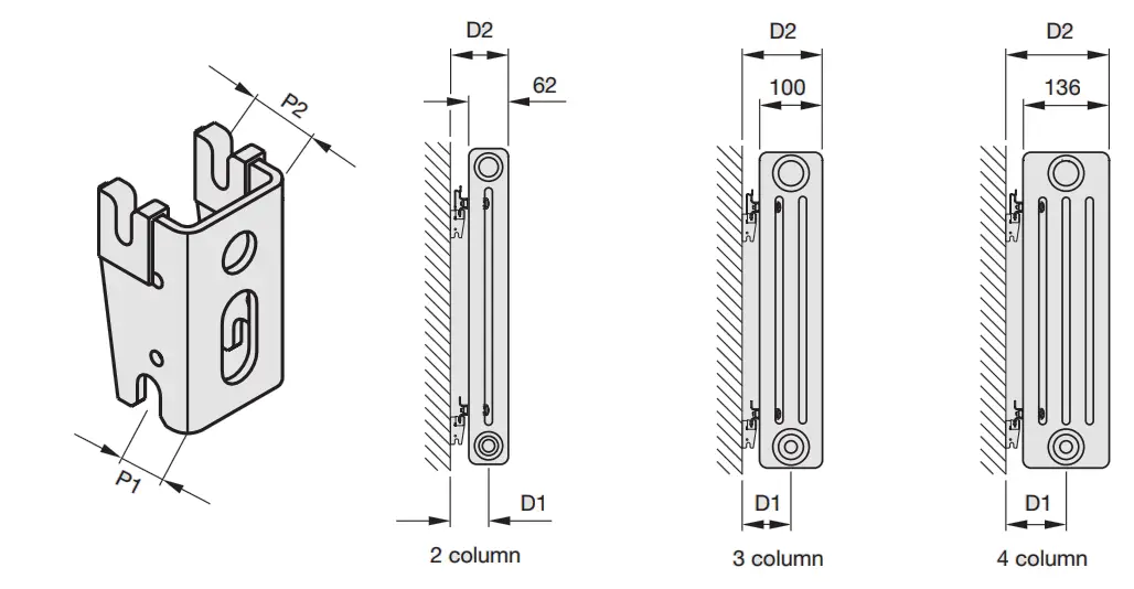
| P1 | 1 P2 | ||
| 2 column | D1 | 54 | 59 |
| D2 | 85 | 90 | |
| 3 column | D1 | 73 | 78 |
| D2 | 123 | 128 | |
| 4 column | D1 | 91 | 96 |
| D2 | 159 | 164 | |
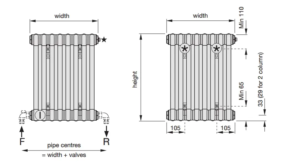
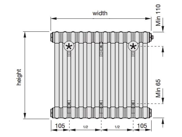
 = Security Clip **
 = Diverter
 = Air Vent
All dimensions shown are in millimetres
Test pressure: 15 BAR
Max working pressure: 10 BAR
Max working temperature: 110º C
All steel construction: dia 25mm tubes
Connections: 1/2 inch BSP btm opp end tappings
Not suitable for use on domestic hot water system
Heat output determined in accordance with EN 442
Test Laboratory: WSP-LAB, Test Lab Registration No: 1428

ISO9001
ISO14001
ISO50001