Albero
CTR-30C RGB LED Auto-Flashing Christmas Tree DIY Kit
User Manual
Introduction:
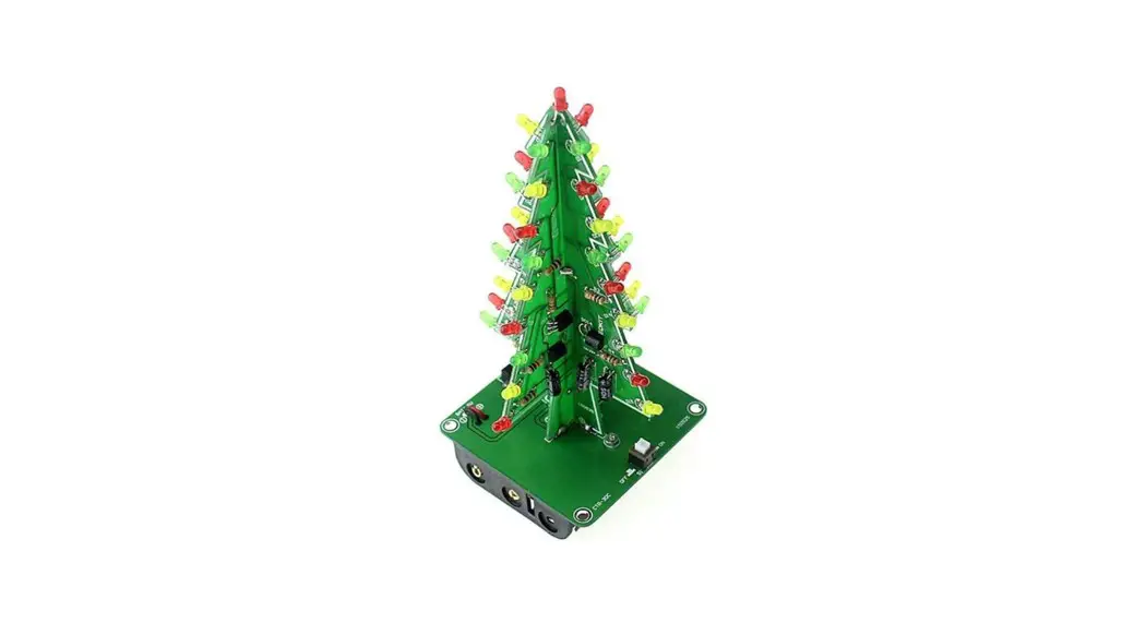
CTR-30C is a RGB LED Auto-Flashing Christmas Tree DIY Kit consists of three circuit board, allows 37pcs LED flash alternately,showing a Christmas tree in the space of three-dimensional profile (the night environment has better viewing) It can be used for Christmas, event celebrations and parties, etc. It can be used to create a festive atmosphere. It is a very interesting DIY electronic product which enables users to understand the circuit more clearly and learn soldering skills.
Feature:
- 37pcs highlight LED
- RGB LED Audio Flash
- Comes with battery box for easy storage
- Perfect simple circuit
- DIY Hand Soldering
Parameter:
- Product Name:CTR-30C RGB LED Auto-Flashing Christmas Tree
- Product Number:CRT-30C
- Work Voltage:DC 4.5V-5.0V
- Work Current:190mA (brightest when R2/R4/R6 are Oohm)
- Power Type:Battery Box and 3.5mm Power Socket
- Work Mode:LED Auto-Flashing
- Color:RGB LED
- Work Temperature:-20C-85C
- Work Humidity:5%-85%RH
- Size(Installed):136*60*60mm
Component listing:
| NO. | Component Name | PCB Marker | Parameter | QTY |
| CTR-30A | ||||
| 1 | Metal Film Resistor | R2,R4,R6 | 150ohm | 3 |
| 2 | Metal Film Resistor | R7 | 470ohm | 1 |
| 3 | Metal Film Resistor | R1,R3,R5 | 10K | 3 |
| 4 | Electrolytic Capacitor | C1-C3 | 47uF 16V | 3 |
| 5 | White LED | D1-D18 | 3mm | 19 |
| 6 | S9014 Transistor | Q1-Q3 | TO-92 | 3 |
| 7 | PCB | CTR-30A | 1 | |
| CTR-30B | ||||
| 8 | Metal Film Resistor | R2,R4,R6 | 150ohm | 3 |
| 9 | Metal Film Resistor | R1,R3,R5 | 10K | 3 |
| 10 | Electrolytic Capacitor | C1-C3 | 47uF 16V | 3 |
| 11 | White LED | D1-D18 | 3mm | 18 |
| 12 | S9014 Transistor | Q1-Q3 | TO-92 | 3 |
| 13 | PCB | CTR-30B | 1 | |
| CTR-30C | ||||
| 14 | Self-Locking Switch | 51 | 5.8mm | 1 |
| 15 | DC Power Socket | J1 | 3.5mm | 1 |
| 16 | Battery Box | AA”3 | 1 | |
| 17 | USB to DC 3.5mm Cable | 80cm | 1 | |
| 18 | Screw | M2*8mm | 2 | |
| 19 | Nut | M2 | 2 | |
| 20 | PCB | CTR-30C | 1 | |
| Note: Users can complete the installation according to the PCB silk screen and component list. | ||||
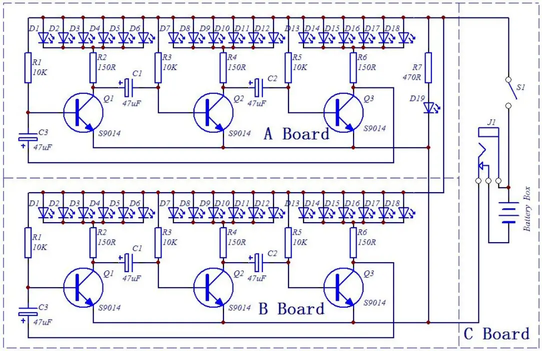
Schematic:
Application:
- Training welding skills
- Student school
- DIY production
- Project Design
- Electronic competition
- Gift giving
- Crafts collection
- Home decoration
- Souvenir collection
- Graduation design
- Holiday gifts
Installation Tips:
- User needs to prepare the welding tool at first.
1.1>.Soldering iron (<50 Watt)
1.2>.Rosin core (“radio”) solder
1.3>.Wire cutters
1.4>.Wire strippers
1.5>.Philips screwdriver - Please be patient until the installation is complete.
- The package is DIY kit.It need finish install by user.
- The soldering iron can’t touch the components for a long time(3s), otherwise damage components.
- Pay attention to the positive and negative of the components.
- Strictly prohibit short circuit.
- User must install the LED according to the specified rules.Otherwise some LED will not light.
- Install complex components preferentially.
- Make sure all components are in right direction and right place.
- Check that all of the LED can be illuminated.
- It is strongly recommended to read the installation manual before starting installation!!!
- Please wear anti-static gloves or anti-static wristbands when installing electronic components.
Installation Steps(Please be patient install!!!):
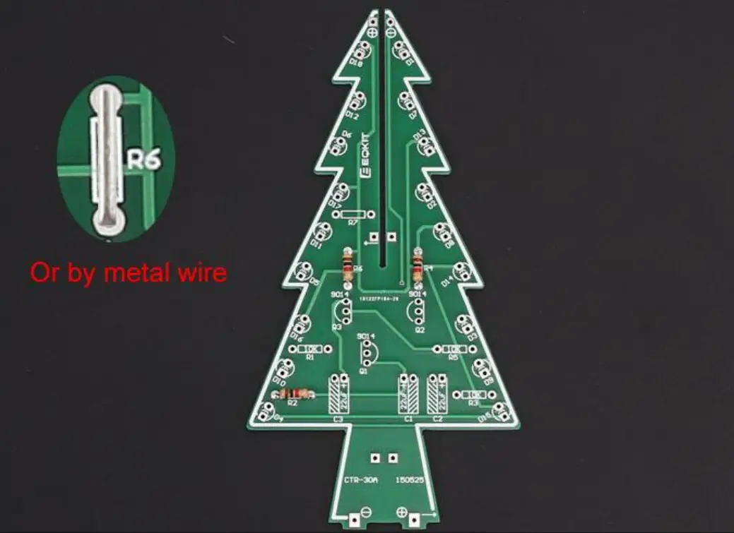
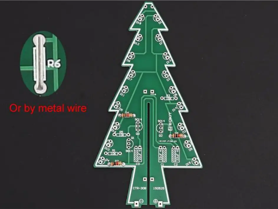
- Step 1: Install 3pcs 150ohm Metal Film Resistors at R2,R4,R6 on CTR-30A.
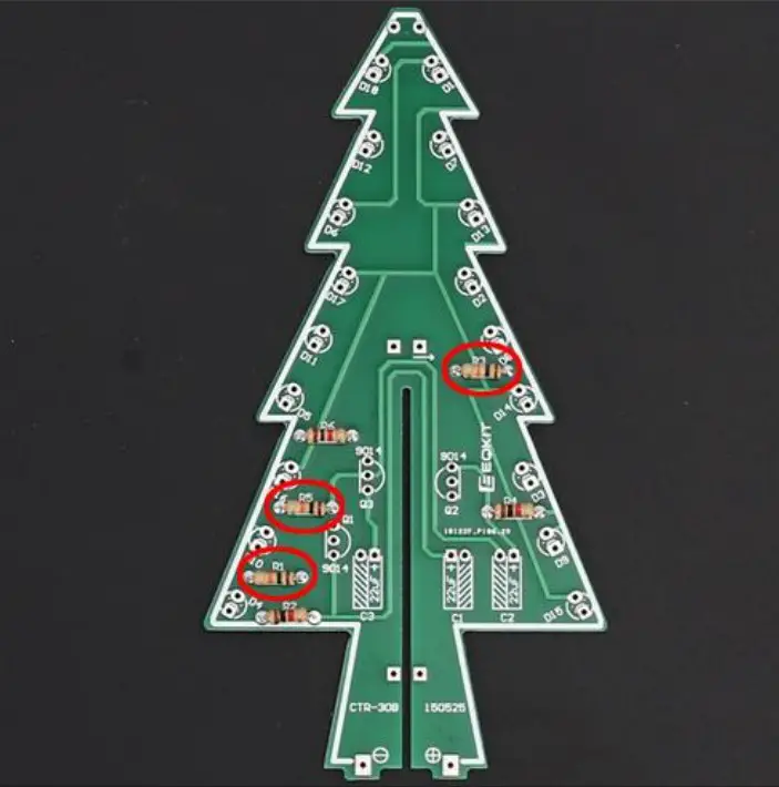
Note: The smaller the resistor value, the brighter the LED. R2/R4/R6 can be 0~470ohm. So user can replace resistor with 0ohm metal wires which can cut extra pins from others components. - Step 2: Install 3pcs 10Kohm Metal Film Resistors at R1,R3,R5 on CTR-30A.
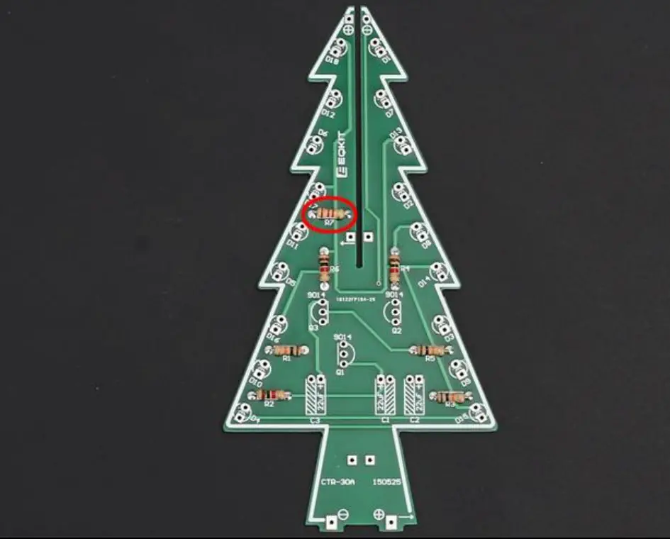
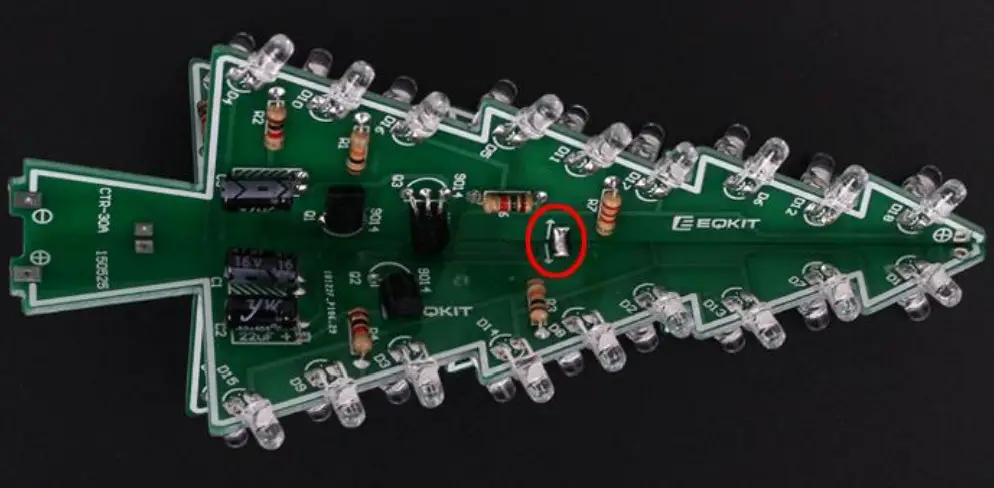
- Step 3: Install 1pcs 470ohm Metal Film Resistors at R7 on CTR-30A.
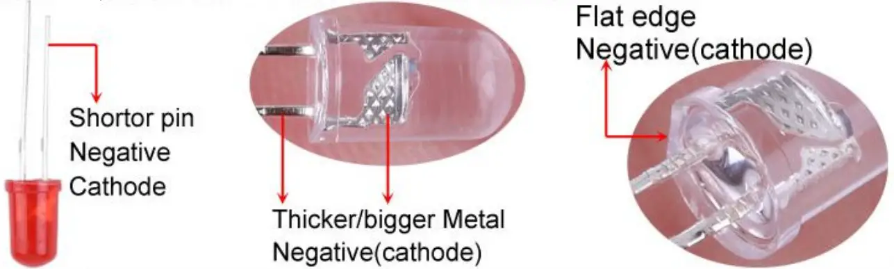
- Step 4: Identify the positive(anode) and negative(cathode) lead of LED.The leads of the LED must be installed correctly, otherwise the LED cannot be turned on.Here are four methods as following:
4.1>.According to the length of the LED lead to distinguish. The longer pin is positive(anode) lead.
The shorter pin is negative(cathode) lead.
4.2>.Identify the negative(cathode) of the LED is to look into the plastic case where one can see that the negative(cathode) is much thicker/bigger inside the plastic case than the anode lead.
4.3>.Identify by edge of plastic case.The negative(cathode) lead of the LED should be the pin nearest the flat on the plastic case.
4.4>.Test by 3V battery or multimeter.The pin is positive(anode) lead which has connect to the positive of 3V if LED can light up after connect 3V power supply.(LED should not be powered directly from the 3V for a short time:less then 0.5second)
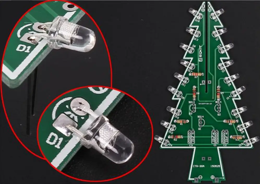
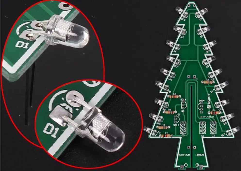
4.5>.It is positive(anode) where the white mark “ + ” pointing to on PCB. - Step 5: Pay attention to the placement of the LED and then install 18pcs 3mm RGB LED at D1-D18 on CTR-30A and bend the metal pins of the LED as shown for easy mounting. The square pad is the positive pole.
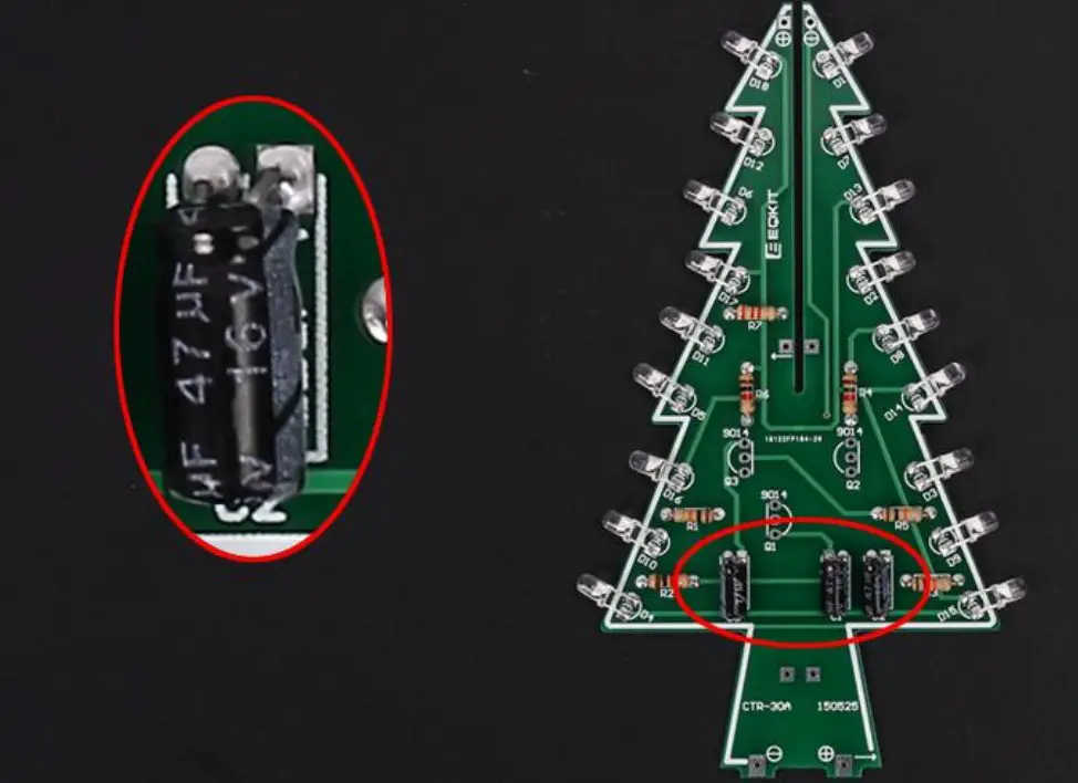
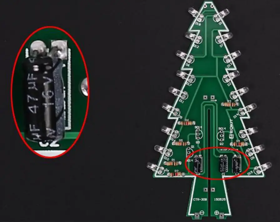
- Step 6: Install 3pcs 47uF 16V Electrolytic Capacitor at C1,C2,C3 on CTR-30A. Pay attention to distinguish between positive and negative. The Longer pin is positive pole.
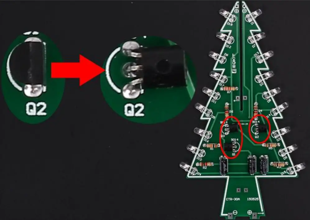
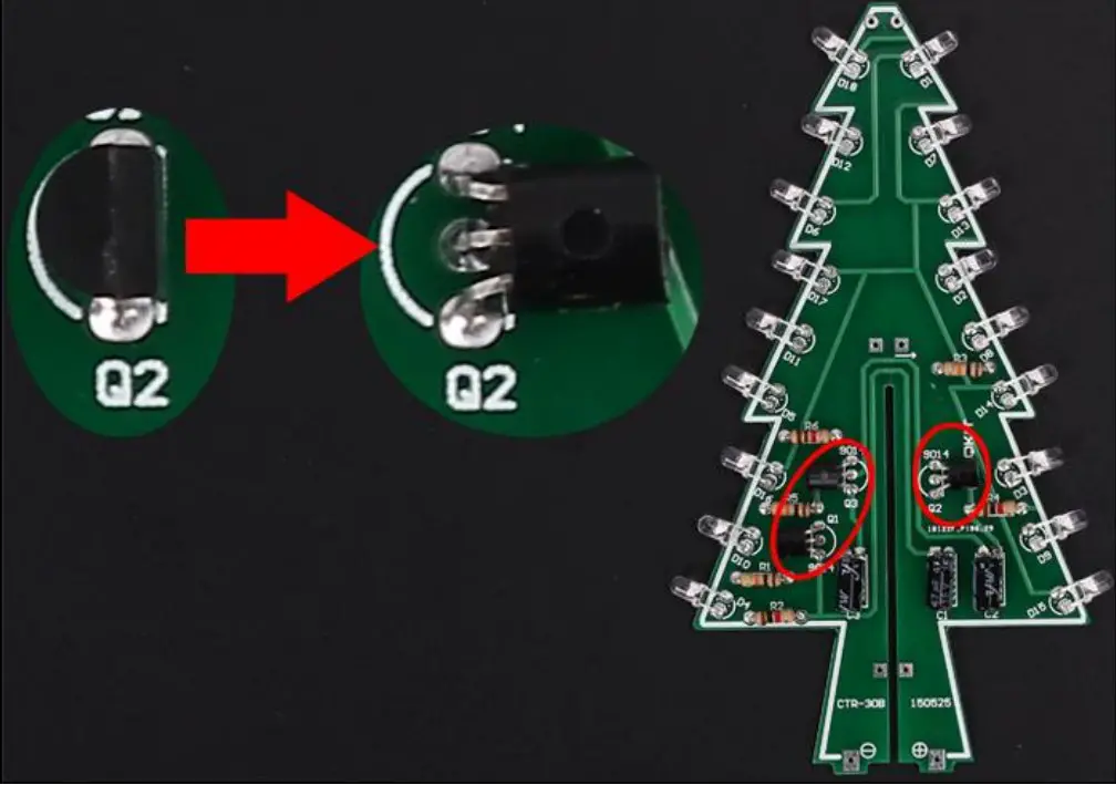
Note: The capacitor needs to be placed horizontally which in order to facilitate the splicing of PCB later. - Step 7: Install 3pcs TO-92 S9014 Transistor at Q1,Q2,Q3 on CTR-30A then bend again which in order to facilitate the splicing of PCB later. Pay attention to the installation direction. The arc on the PCB corresponds to the arc of the components.
- Step 8: Install 3pcs 150ohm Metal Film Resistors at R2,R4,R6 on CTR-30B. Note: The smaller the resistor value, the brighter the LED. R2/R4/R6 can be 0~470ohm.So user can replace resistor with 0ohm metal wires which can cut extra pins from others components.
- Step 9: Install 3pcs 10Kohm Metal Film Resistors at R1,R3,R5 on CTR-30B.
- Step 10: Pay attention to the placement of the LED and then install 18pcs 3mm RGB LED at D1-D18 on CTR-30B and bend the metal pins of the LED as shown for easy mounting. The square pad is the positive pole.
- Step 11: Install 3pcs 47uF 16V Electrolytic Capacitor at C1,C2,C3 on CTR-30B. Pay attention to distinguish between positive and negative. The Longer pin is positive pole.
Note: The capacitor needs to be placed horizontally which in order to facilitate the splicing of PCB later. - Step 12: Install 3pcs TO-92 S9014 Transistor at Q1,Q2,Q3 on CTR-30B then bend again which in order to facilitate the splicing of PCB later. Pay attention to the installation direction. The arc on the PCB corresponds to the arc of the components.
- Step 13: Splicing CTR-30A and CTR-30B, pay attention to align the fixing points, and then fix it with solder tin wire. Pay attention to the splicing direction.
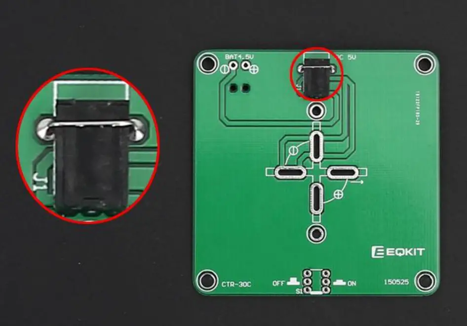
- Step 14: Install 1pcs 3.5mm DC Socket at J1. Tops: Secure the socket with metal wire which cut from components.
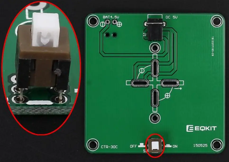
- Step 15: Install 1pcs 5.8*5.8mm Self-locking Switch at S1.
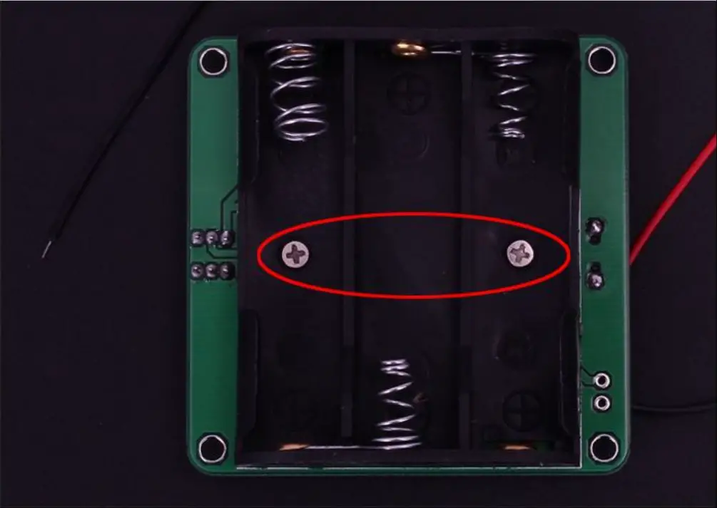
- Step 16: Fix 1pcs AA*3 battery box by 2pcs M2*8mm and 2pcs M2 Nut.
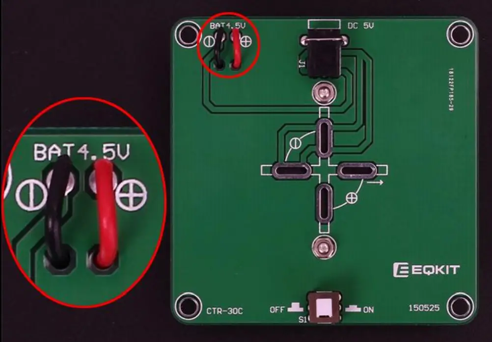
- Step 17: Connect battery wire: Red connect to + and Black wire connect to – .Cut the excess wire.
- Step 18: Fix PCTR-30A and CTR-30B on PCTR-30C. Pay attention to the direction of positive and negative pole. Align each pad and horizontally vertically. Then fix each pad.
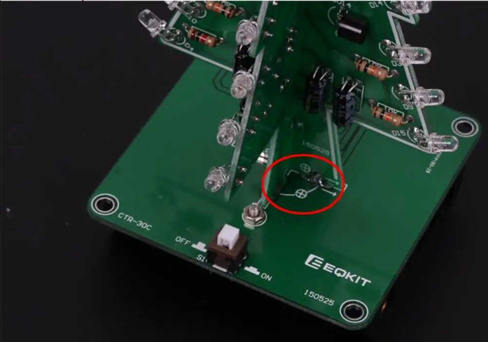
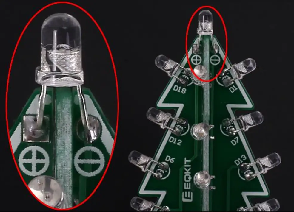
- Step 19: Install 1pcs 3mm RGB LED at top. Pay attention to the direction of positive and negative pole.
Install shown steps:
- Step 1: Install 3pcs 150ohm Metal Film Resistors at R2,R4,R6 on CTR-30A.
Note: The smaller the resistor value, the brighter the LED. R2/R4/R6 can be 0~470ohm. So user can replace resistor with 0ohm metal wires which can cut extra pins from others components.
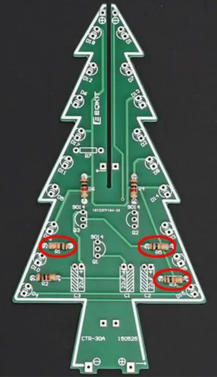
- Step 2: Install 3pcs 10Kohm Metal Film Resistors at R1,R3,R5 on CTR-30A.

- Step 3: Install 1pcs 470ohm Metal Film Resistors at R7 on CTR-30A.

- Step 4: Identify the positive(anode) and negative(cathode) lead of LED.The leads of the LED must be installed correctly, otherwise the LED cannot be turned on.Here are four methods as following:
4.1>.According to the length of the LED lead to distinguish. The longer pin is positive(anode) lead.
The shorter pin is negative(cathode) lead.
4.2>.Identify the negative(cathode) of the LED is to look into the plastic case where one can see that the negative(cathode) is much thicker/bigger inside the plastic case than the anode lead.
4.3>.Identify by edge of plastic case.The negative(cathode) lead of the LED should be the pin nearest the flat on the plastic case.
4.4>.Test by 3V battery or multimeter.The pin is positive(anode) lead which has connect to the positive of 3V if LED can light up after connect 3V power supply.(LED should not be powered directly from the 3V for a short time:less then 0.5second)
4.5>.It is positive(anode) where the white mark “ + ” pointing to on PCB.
- Step 5: Pay attention to the placement of the LED and then install 18pcs 3mm RGB LED at D1-D18 on CTR-30A and bend the metal pins of the LED as shown for easy mounting. The square pad is the positive pole.

- Step 6: Install 3pcs 47uF 16V Electrolytic Capacitor at C1,C2,C3 on CTR-30A. Pay attention to distinguish between positive and negative. The Longer pin is positive pole.
Note: The capacitor needs to be placed horizontally which in order to facilitate the splicing of PCB later.
- Step 7: Install 3pcs TO-92 S9014 Transistor at Q1,Q2,Q3 on CTR-30A then bend again which in order to facilitate the splicing of PCB later. Pay attention to the installation direction. The arc on the PCB corresponds to the arc of the components.
- Step 8: Install 3pcs 150ohm Metal Film Resistors at R2,R4,R6 on CTR-30B. Note: The smaller the resistor value, the brighter the LED. R2/R4/R6 can be 0~470ohm.So user can replace resistor with 0ohm metal wires which can cut extra pins from others components.

- Step 9: Install 3pcs 10Kohm Metal Film Resistors at R1,R3,R5 on CTR-30B.

- Step 10: Pay attention to the placement of the LED and then install 18pcs 3mm RGB LED at D1-D18 on CTR-30B and bend the metal pins of the LED as shown for easy mounting. The square pad is the positive pole.

- Step 11: Install 3pcs 47uF 16V Electrolytic Capacitor at C1,C2,C3 on CTR-30B. Pay attention to distinguish between positive and negative. The Longer pin is positive pole.
Note: The capacitor needs to be placed horizontally which in order to facilitate the splicing of PCB later.
- Step 12: Install 3pcs TO-92 S9014 Transistor at Q1,Q2,Q3 on CTR-30B then bend again which in order to facilitate the splicing of PCB later. Pay attention to the installation direction. The arc on the PCB corresponds to the arc of the components.

- Step 13: Splicing CTR-30A and CTR-30B, pay attention to align the fixing points, and then fix it with solder tin wire. Pay attention to the splicing direction.

- Step 14: Install 1pcs 3.5mm DC Socket at J1. Tops: Secure the socket with metal wire which cut from components.

- Step 15: Install 1pcs 5.8*5.8mm Self-locking Switch at S1.

- Step 16: Fix 1pcs AA*3 battery box by 2pcs M2*8mm and 2pcs M2 Nut.

- Step 17: Connect battery wire: Red connect to + and Black wire connect to – .Cut the excess wire.

- Step 18: Fix PCTR-30A and CTR-30B on PCTR-30C. Pay attention to the direction of positive and negative pole. Align each pad and horizontally vertically. Then fix each pad.

- Step 19: Install 1pcs 3mm RGB LED at top. Pay attention to the direction of positive and negative pole.

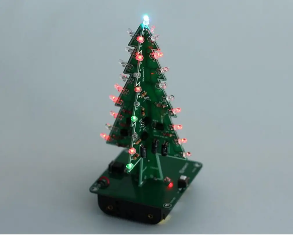
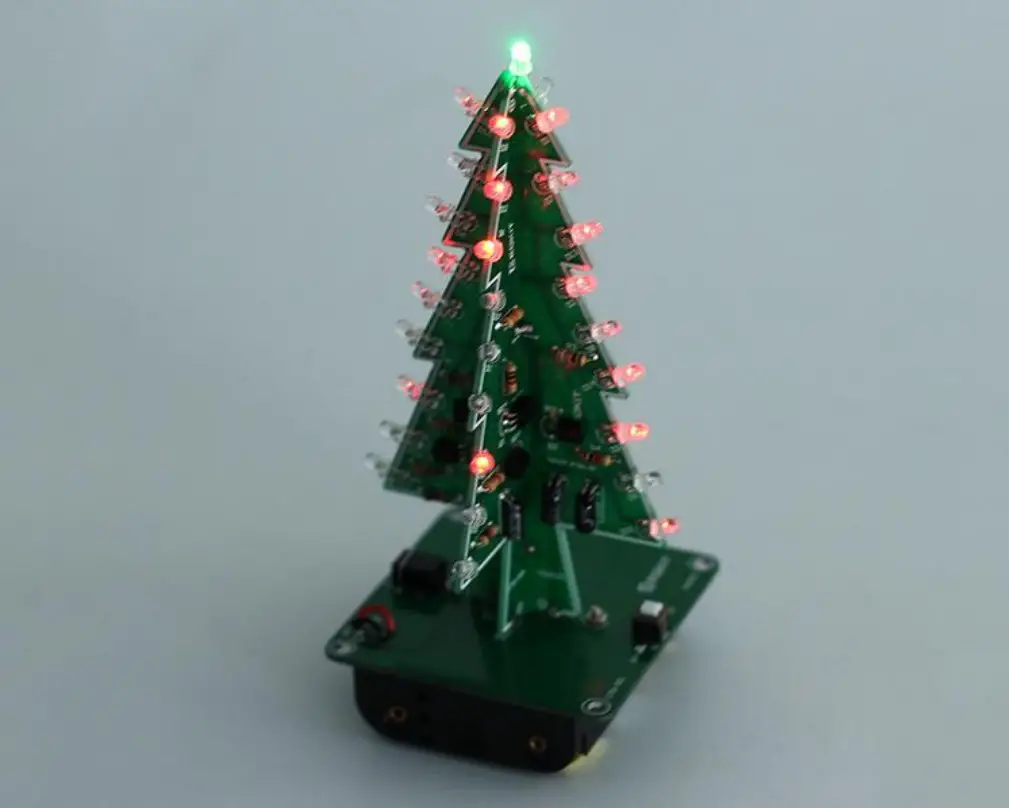
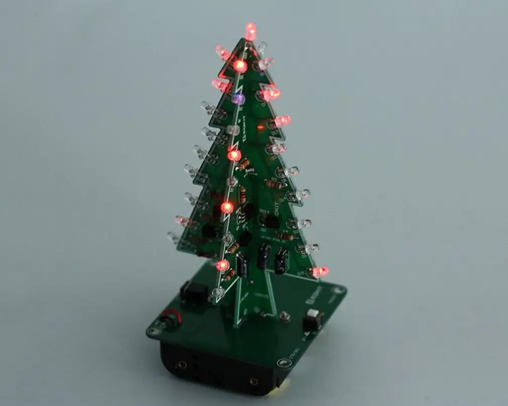
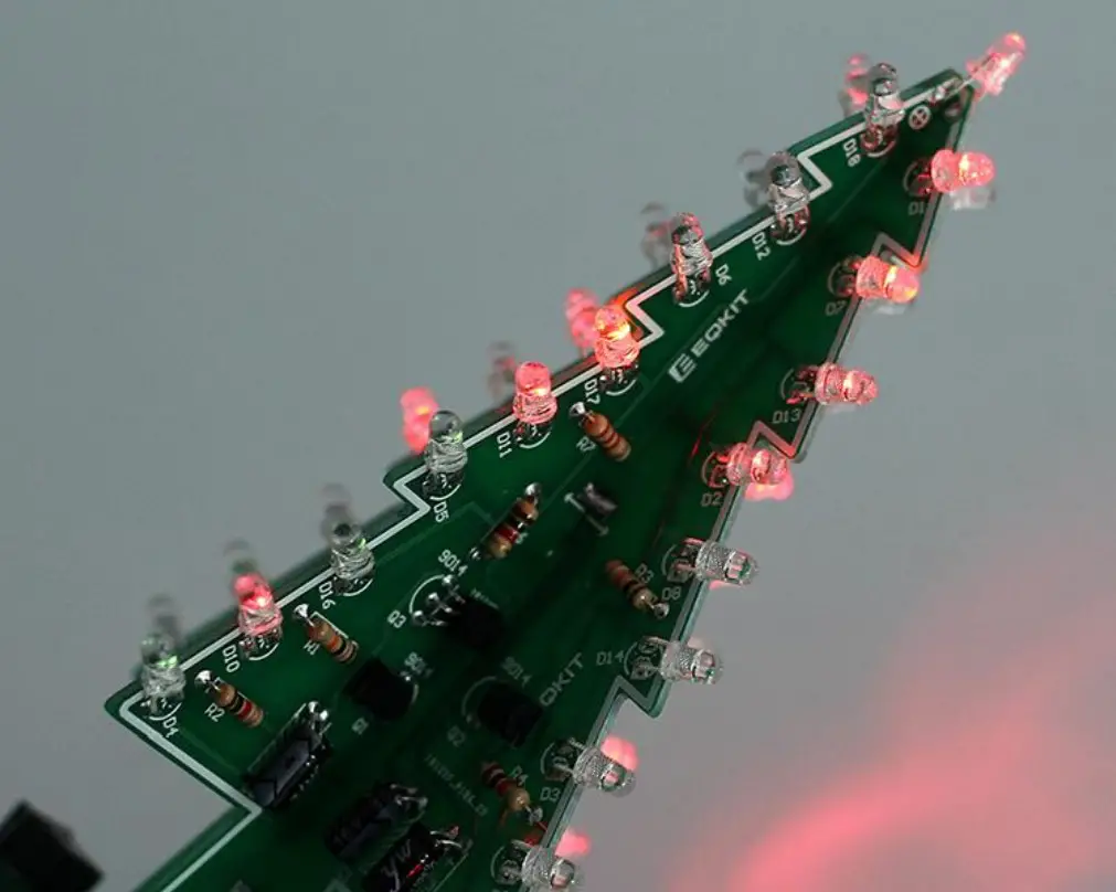
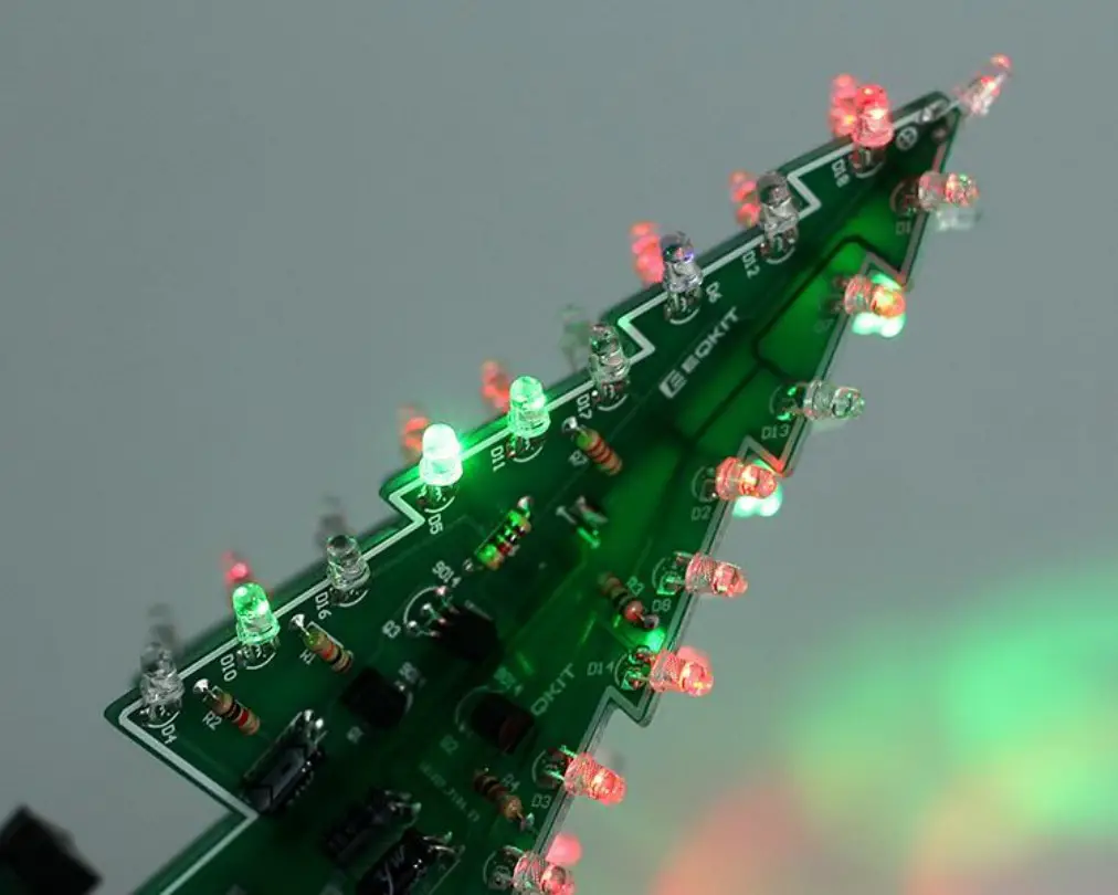
Effect demonstration:
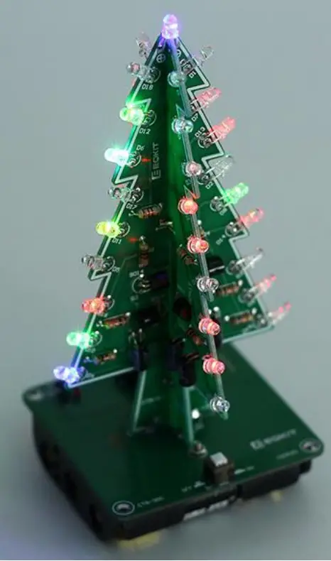
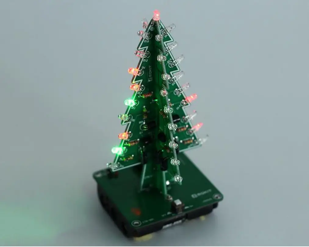 |  |
 |  |
 |  |


