![]()
PD-IM-7504B Marketing Board
– User Guide
Preliminary
Revision 1.1
PD-IM-7504B Marketing Board
PRODUCTION DATA – Information contained in this document is proprietary to Microsemi and is current as of the publication date. This document may not be modified in any way without the express written consent of Microsemi. Product processing does not necessarily include testing of all parameters. Microsemi reserves the right to change the configuration and performance of the product and to discontinue the product at any time.
About this Guide
This user guide provides both a description and operation procedures for Microsemi’s PD-IM-7504B Marketing Board, which is used to evaluate the performance of D69104A/B/B1 PoE applications.
1.1 Audience
This user guide is intended for qualified personnel, meaning operators and technicians who have a background in electronics and are familiar with its basic concepts.
1.2 Organization
This guide is divided into several sections as follows:
| CHAPTER 1 | About this Guide: Describes the guide’s objectives, audience, and organization. |
| CHAPTER 2 | Introduction: Describes PoE Marketing board overview, main functions, features, physical characteristics, and ordering information. |
| CHAPTER 3 | Physical Description: Provides explanation that relates to the physical description (switches, jumpers, connectors). |
| CHAPTER 4 | Electrical Characteristics: Provides electrical characteristics of the PoE Marketing board. |
| CHAPTER 5 | Installation: Describes installation process. |
| CHAPTER 6 | Relevant Documents: Details of other documents relevant to the Marketing Board. |
Introduction
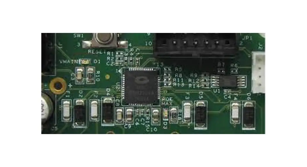
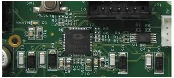
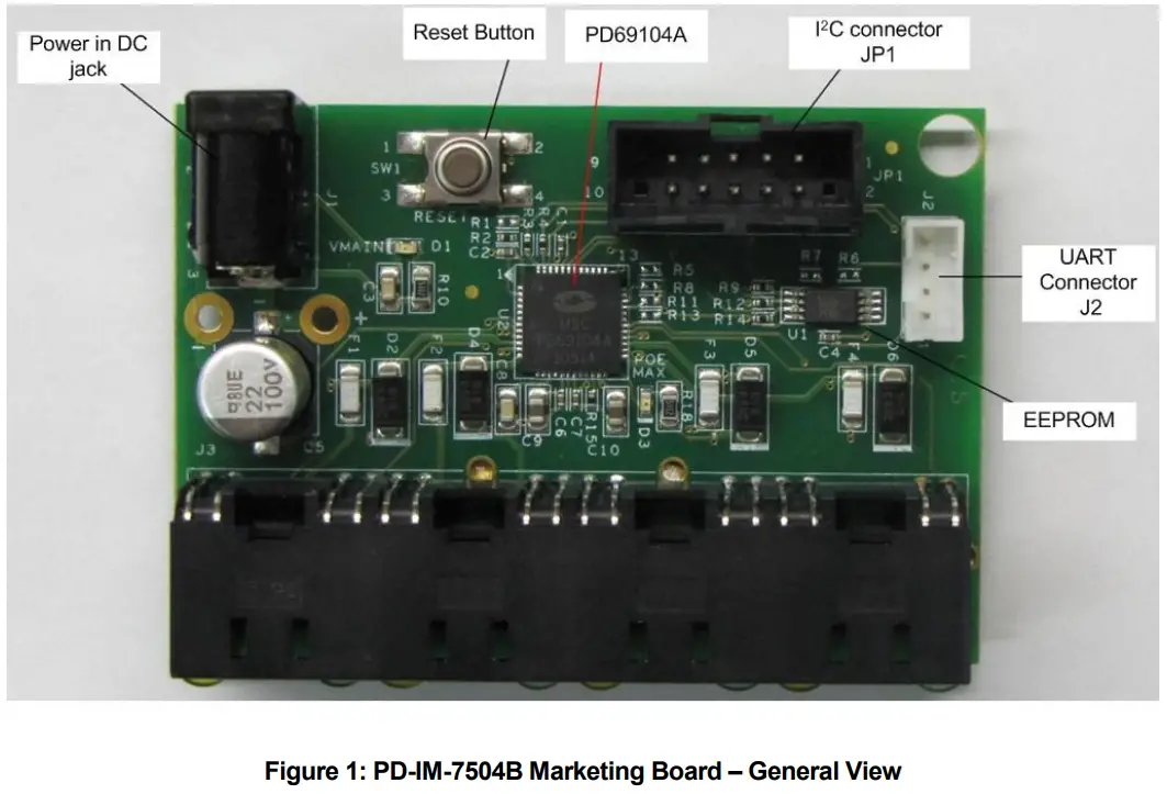
Microsemi’s PD-IM-7504B Marketing Board (see Figure 1) provides designers with the needed environment to evaluate the performance and implementation of PoE and PoE extended mode applications, based on PD69104A/B/B1 PoE Manager. The marketing board enables PoE designers to evaluate Microsemi’s PoE solution with maximum flexibility and ease in configuration
All necessary steps and connection instructions required for installing and operating this board are provided within this document.
2.1 Marketing Boards Ordering Information
Microsemi supplies the following Marketing Boards as detailed below:
| Ordering Number | Description |
| PD-IM-7504A | 1 Marketing Board that simulates a 4 ports PoE. |
2.2 Marketing Board Features
- Designed to support four RJ45 ports, PoE application, and PoE extended mode (2-pairs)
- Vin connector – DC jack
- On-board LEDs indicators
- Reset button
- EEPROM support
- I2C and UART communication connectors.
- Marketing Board working temperature: 0°c to +50°c
- RoHS compliant
2.3 Marketing Board Interfaces and Connections
Board has several interfaces:
- RJ45 interface: Running from PD69104A/B/B1 to 4 PDs (powered devices)
- Vin connectors: DC in (Vmain) connection (J1)
- LEDs indication: Vmain power OK, Power limit LEDs
- UART connector: for UART communication.
- I²C connector: for I²C communication or EEPROM configuration.
2.4 Physical Characteristics
The following table lists the Marketing Board’s physical characteristics.
Physical Characteristics
| Parameter | Value |
| Mechanical dimensions | 66 x 45 x 16 mm (L x W x H) |
2.5 Communication
- I²C –Marketing Board is set to work with I2C communication through connector JP1, with Aardvark (http://www.totalphase.com/products/aardvark_i2cspi/) or any other I²C master.
| Pin | JP1 Description |
| 1 | SCL |
| 2 | GND |
| 3 | SDA |
| 4 | |
| 5 | |
| 6 | |
| 7 | |
| 8 | |
| 9 | |
| 10 | WP ** |
** When configuring EEPROM, connect this pin to GND.
- UART- connecting through J2 pins:
| Pin | J2 Description |
| 1 | 3.3V (out) |
| 2 | Tx |
| 3 | Rx |
| 4 | GND |
- E² PROM – When no host controls the IC and configuration should be other than the default, an EEPROM may be used for uploading new configurations. EEPROM can be burned by JP1.
Physical Description
3.1 Package Contents
Upon opening the Marketing Board package, verify all parts itemized in the packing list are included. If any part is missing or seems damaged; contact a local representative or Microsemi’s Headquarters. Package contents for standard shipments are as follows:
- PD-IM-7504B Marketing Board
- 55V power supply Adapter + AC cord
3.2 Reset Button
The dedicated Reset button SW1 (see Figure 1) is utilized to reset the PD69104A/B/B1 PoE manager.
3.3 Connectors
The following sections provide both general and detailed information regarding unit connectors.
3.3.1 Connectors Table
The following table lists Marketing Board’s connectors.
Table 1: Connectors List
| # | Connector | Name | Description |
| 1 | J1 | Vin DC jack | 44V-57V DC input (Vmatn) connection used for powering the Marketing Board |
| 2 | J2 | UART connector | UART communication connector. (3.3V compatible) Can use PD-0600 (Microsemi USB to UART converter) or any equivalent equipment |
| 3 | J3 | RJ45 connectors | Four RJ45 ports for connecting to the powered device |
| 4 | JP1 | 12C connector | Connection to I2C communication through AARDVARK or any other equivalent equipment (3.3V compatible) |
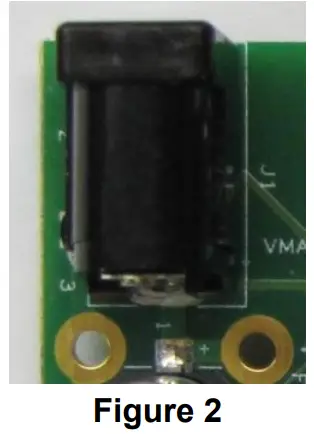
3.4 Vin DC jack connectors (J1)
See Figure 2.
DC in (Vmain) connection, used to power Marketing Board, 44V > Vmain > 57VDC.
Table 2: Vin Connectors
| Pin No. | Signal Name | Description |
| 1 | Vain (Vin +) | Positive main voltage (referenced to AGND) |
| Hole 1(right) | Vain (Vin +) | Used for soldering wires to the external power supply |
| Hole 2(left) | GND(Vin -) | Used for soldering wires to the external power supply |
Since provided power supply can’t support four ports PoE + full load (4*0.6A=2.4A), a wired connection can be used for connecting the laboratory power supply directly to PCB using the holes located near J1.
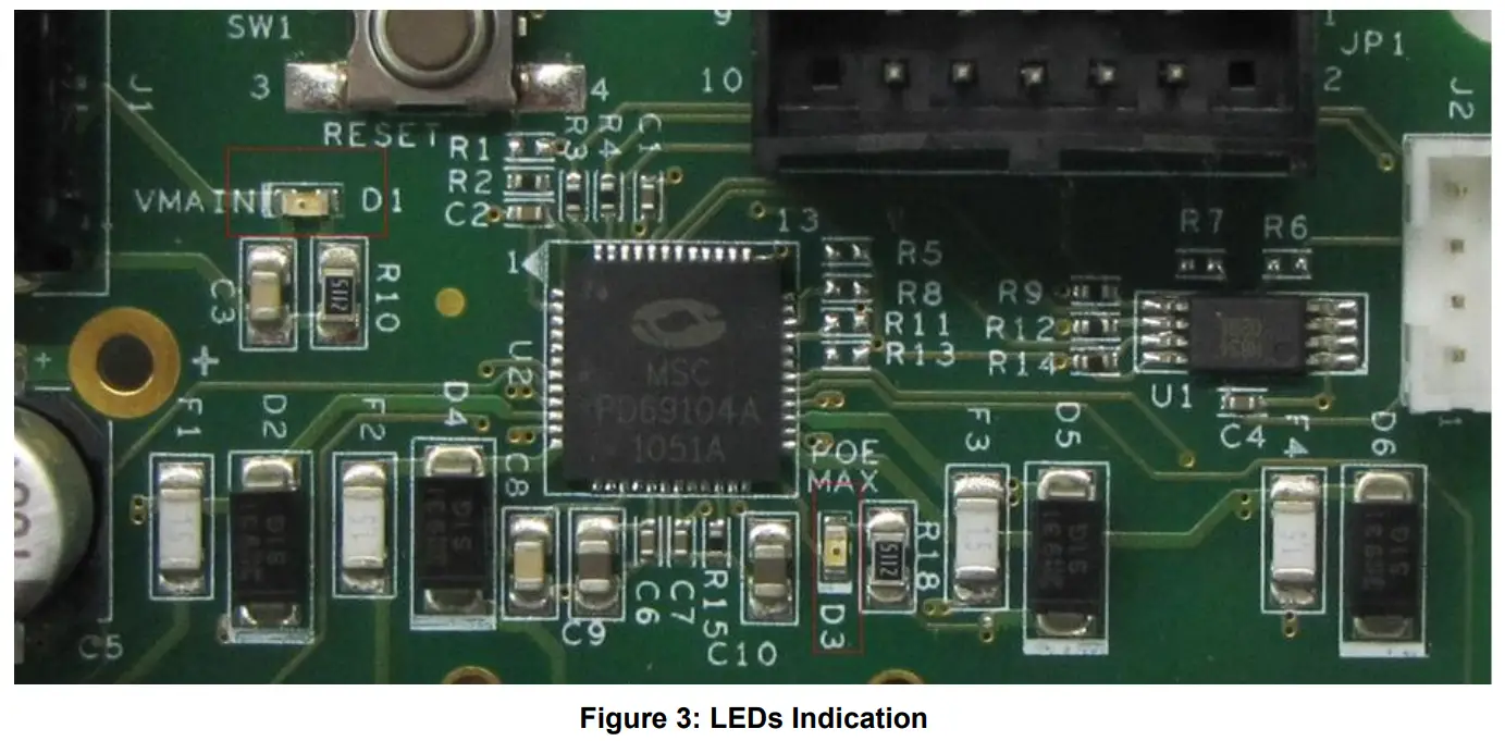
3.5 LEDs Indication
- D1 – VMAIN indication.
- D3 – MAX power indication. (Indicates power budget is reaching its limit)
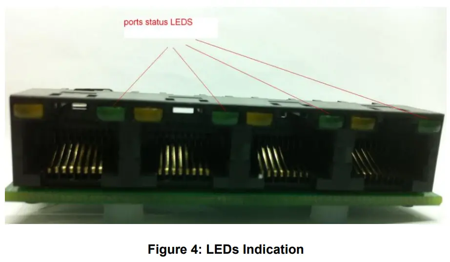
- Port Status LED– in front of each port in the RJ45 connector there is a green LED that indicates whether the port is operating. See Figure 4
Electrical Characteristics
The marketing board’s electrical characteristics are listed below:
Table 3: Electrical Characteristics
| Parameter | Symbol | Min. | Max. | Units |
| Main DC supply Vain | Vin | 44 | 57 | V |
| Port current | About | 0.6 | A |
Installation
This chapter describes the steps required for installing and operating the Marketing Board with any PoE application.
5.1 Preliminary Considerations and Safety Precautions
- Prior to powering the board, connect all required peripherals.
- Never hot swap peripherals units!
- Verify board is properly configured prior to turning on the power supply.
5.2 Default Configuration
- The current set is configured to AT mode (600mA). If the “AF” current (350mA) has to be changed, load 0Ω to R11.
- Communication mode set to I²C (R5 is loaded with 0Ω). If UART is required, disconnect R5 and connect 0Ω to R8.
- PoE Auto mode.
All configurations can be set by communication or EEPROM.
Relevant Documents
- PD69104A datasheet, catalog number DS_PD69104A
- PD69104B datasheet, catalogue number DS_PD69104B
- PD69104B1 datasheet, catalogue number DS_PD69104B1
- Serial Communication Protocol user guide PD63000_UG
- PD69104A reg. map user guide, catalog number 06-0480-056
- PD69104B reg. map user guide, catalogue number PD69104B_GENERIC_UG_REG_MAP
- Marketing board schema PD-1358G201
- PD69104B Based Design of a 4-port Auto Mode System AN-198, catalog number 06-0134-080
The information contained in the document (unless it is publicly available on the Web without access restrictions) is the PROPRIETARY AND CONFIDENTIAL information of Microsemi and cannot be copied, published, uploaded, posted, transmitted, distributed or disclosed, or used without the express duly signed written consent of Microsemi. If the recipient of this document has entered into a disclosure agreement with Microsemi, then the terms of such Agreement will also apply. This document and the information obtained herein may not be modified, by any person other than authorized personnel of Microsemi. No license under any patent, copyright, trade secret, or other intellectual property right is granted to or conferred upon you by disclosure or delivery of the information, either expressly, by implication, inducement, estoppels, or otherwise. Any license under such intellectual property rights must be approved by Microsemi in writing and signed by an officer of Microsemi.
Microsemi reserves the right to change the configuration, functionality, and performance of its products at any time without any notice. This product has been subject to limited testing and should not be used in conjunction with life support or other mission-critical equipment or applications. Microsemi assumes no liability whatsoever, and Microsemi disclaims any express or implied warranty, relating to the sale and/or use of Microsemi products including liability or warranties relating to fitness for a particular purpose, merchantability, or infringement of any patent, copyright, or another intellectual property right. Any performance specifications believed to be reliable but are not verified and the customer or user must conduct and complete all performance and another testing of this product as well as any user or customer’s final application. User or customer shall not rely on any data and performance specifications or parameters provided by Microsemi. It is the customer’s and user’s responsibility to independently determine the suitability of any Microsemi product and to test and verify the same. The information contained herein is provided “AS IS, WHERE IS” and with all faults, and the entire risk associated with such information is entire with the User. Microsemi specifically disclaims any liability of any kind including for consequential, incidental, and punitive damages as well as lost profit. The product is subject to other terms and conditions which can be located on the web at http://www.microsemi.com/legal/tnc.asp
Revision History
| Revision Level / Date | Para. Affected/Page | Description |
| 1.0 / 10-Feb-11 | Initial revision | |
| 1.1 / 09-June-13 | Update to support PD69104B/1 |
For support contact: [email protected]
Visit our website at: www.microsemi.com
Catalog Number: PD69104B_UG_EVB
Microsemi
Analog Mixed Signal Group
Copyright © 2013
Rev. 1.1, 09-June-13
1 Enterprise, Aliso Viejo, CA 92656, USA;
Within the USA: (800) 713-4113,
Outside the USA: (949) 221-7100
Fax: (949) 756-0308
Downloaded from Arrow.com.


