
EBYTE SM-CO-P01 Carbon Monoxide Module
Disclaimer
EBYTE reserves all rights to this document and the information contained herein.
Products, names, logos and designs described herein may in whole or in part be subject to intellectual property rights. Reproduction, use, modification or disclosure to third parties of this document or any part thereof without the express permission of EBYTE is strictly prohibited.
The information contained herein is provided “as is” and EBYTE assumes no liability for the use of the information. No warranty, either express or implied, is given, including but not limited, with respect to the accuracy, correctness, reliability and fitness for a particular purpose of the information. This document may be revised by EBYTE at any time. For most recent documents, visit www.ebyte.com.
Note:
The contents of this manual are subject to change due to product version upgrades or other reasons. Chengdu Ebyte Electronic Technology Co.,Ltd. reserves the right to make changes to the contents of this manual without notice or suggestion. This manual serves only as a user guide and Chengdu Ebyte Electronic Technology Co.,Ltd. endeavors to provide accurate information in this manual, but Chengdu Billionaire Electronics Co., Ltd. does not ensure that the contents are completely error-free and that all statements, information and suggestions in this manual do not constitute any express or implied warranty.
Product Overview
Brief Introduction
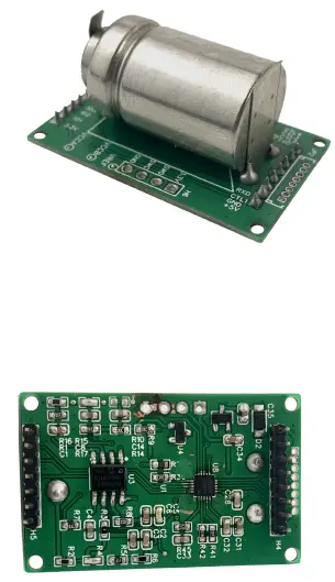
This module is widely used in the whole machine development of household gas leakage alarm and gas leakage detection components. The input power supply, induction probe and signal output in the sensor are completely isolated. Safe and reliable, small size, easy to install.
Feature
This product adopts high-sensitivity electrochemical probe with stable signal and high precision. It has the characteristics of wide measurement range, fast response speed, convenient use and easy installation. In particular, it has the basic functions of a household gas leakage alarm, and only needs external status indication, buzzer, relay, and solenoid valve to achieve the function of a household gas leakage alarm that meets the national standard.
Main parameters
| detect gas | carbon monoxide (gas) |
| sensor type | Electrochemistry |
| Interface Type | 8pin and 7pin 2.0mm header |
| Signal output | TTL serial port (Modbus-RTU protocol) |
| Response time | ≤30 s |
| Recovery Time | ≤30 s |
| Operating Voltage | DC 4.8V~5.3V |
| Working current | ≤5mA |
| Measurement range | 0~10000PPM |
| Resolution | 1PPM |
| Alarm value | Can be set (default 150PPM) |
| precision | ±50PPM (when the concentration is 150PPM) |
| life expectancy | 10 Year |
| follow the standard | National standard GB 15322.2 |
| Use environment | Temperature: -10 ~ 55 ℃ Humidity: 20% ~ 90% RH |
| storage environment | Temperature: -20 ~ 60 ℃ Humidity: 20% ~ 65% RH |
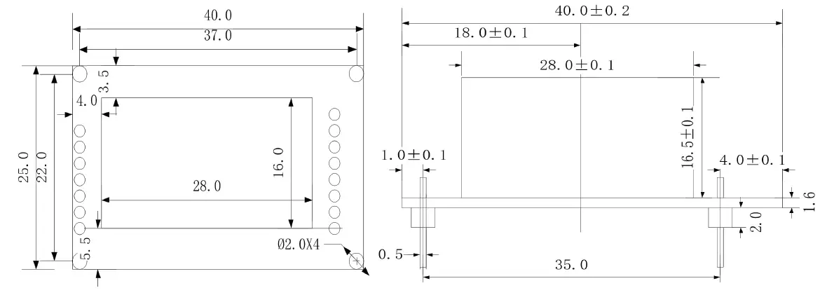
| Dimensions | 40mm×25mm×24mm |
 Pin function description
| pin number | definitio n | Function Description |
| 1 | VCC | 5V module power input |
| 2 | GND | reference place |
| 3 | CTL1 | Control output 1: 1. Continuously low level when there is no alarm or fault. 2. In the alarm state, the continuous high level. |
| 4 | RXD | Serial port RXD data receiving pin |
| 5 | TXD | Serial port TXD data transmission pin |
| 6 | CTL2 | Control output 2: 1. Continuously low level when there is no alarm or fault. 2. In the alarm state, the continuous high level. |
| 7 | CTL3 | Control output 3, buzzer control: high level beep |
| 8 | CTL4 | Control output 4, fault light control: high level on, low level off |
| 9 | VDD | Module 3.3V output, output current <100mA |
| 10 | IO1 | Alarm light control port: high level on, low level off |
| 11 | IO2 | Power light control port: high level on, low level off |
| 12 | IO3 | Self-test key input port: low level key is valid |
| 13 | IO4 | NC (keep floating) |
| 14 | IO5 | NC (keep floating) |
| 15 | IO6 | NC (keep floating) |
Introduction to work status
- Power-on self-test
When the power is turned on, the three lights are turned on in turn. After a delay of about 5 minutes, the buzzer will beep once and enter the normal working state, and the “power” light will flash. - Normal working condition
When the module is in no fault or alarm state, the “Power” light flashes. In this state, press the “self-test” button, the module will perform acousto-optic self-test. - Alarm status
When there is no fault in the module and the gas concentration on site is higher than the alarm setting value, the “alarm” light is always on, the buzzer makes a rapid sound, and a control signal is output. At this point, you can press the “self-test” button to mute the sound.
When the gas concentration drops to within the alarm setting value, the module automatically returns to normal working state. - Fault status
When the sensor fails, the “fault” light is always on, and the buzzer makes intermittent sounds.
| Working status | Fault light (recommended yellow) | warning light (recommende d red) | power light (recommende d green) | buzzer |
| normal status | extinguished | extinguished | flicker | silent |
| fault state | Always bright | extinguished | extinguished | Tweet intermittently |
| Alarm status | extinguished | Always bright | extinguished | Tweet intermittently |
| Self-check status | running water lamp | Keep tweeting 5 times | ||
“Self-check” key: Press the “Self-check” key in normal state to carry out self-check; in alarm state, press the “Self-check” key to silence the alarm.
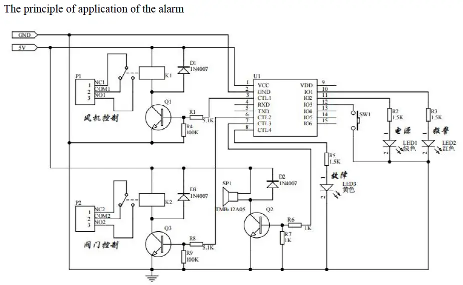
System Frame Diagram
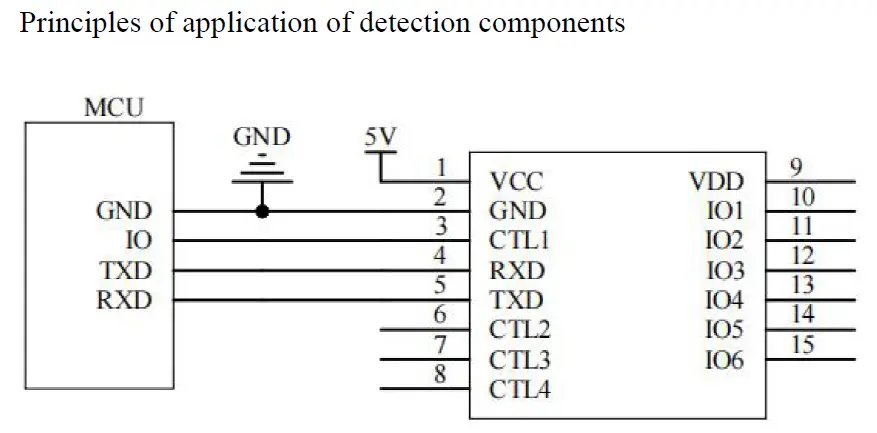
Principles of application of detection components
 Product selection
| SM- | company no. | |||
| CO- | Methane | |||
| P01 | TTL serial communication (Modbus-RTU protocol) | |||
| N01- | 485 serial communication (Modbus-RTU protocol ) | |||
| 8 | Flat card rail shell |
Configuration software installation and use
Our company provides supporting “sensor monitoring software”, which can easily use the computer to read the parameters of the sensor, and flexibly modify the device ID and address of the sensor.
Note that there is only one sensor on the bus when using automatic acquisition by software.
Sensor connected to computer
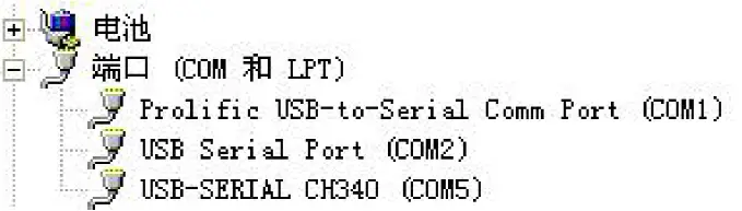
After the sensor is correctly connected to the computer via USB to TTL and provides power, you can see the correct COM port in the computer (check the COM port in “My Computer – Properties – Device Manager – Port”).
 Open the data package, select “Debugging Software”—“Parameter Configuration Software”, find
  and open it.
If the COM port is not found in the device manager, it means that you have not installed the USB to TTL driver (included in the data package) or the driver has not been installed correctly, please contact a technician for help.
Use of Sensor Monitoring Software
- The configuration interface is shown in the figure. First, obtain the serial port number according to the method in Chapter 3.1 and select the correct serial port.
- Click the test baud rate of the software, the software will test the baud rate and address of the current device, the default baud rate is 9600bit/s, and the default address is 0x01.
- Modify the address and baud rate according to the needs of use, and at the same time, you can query the current functional status of the device.
- If the test is unsuccessful, please re-check the equipment wiring and driver installation
Communication protocol
Communication basic parameters
| coding | 8 bit binary |
| data bits | 8 bits |
| parity bit | None |
| stop bit | 1 person |
| error checking | CRC (Redundant Cyclic Code) |
| baud rate | 2400bit/s, 4800bit/s, 9600 bit/s can be set, the factory default is 9600bit/s |
Data Frame Format Definition
Using Modbus-RTU communication protocol, the format is as follows: Initial structure ≥4 bytes of time
- Address code = 1 byte
- Function code = 1 byte
- Data area = N bytes
- Error check = 16-bit CRC code
- Time to end structure ≥ 4 bytes
Address code: the address of the transmitter, which is unique in the communication network (factory default 0x01).
function code:
| function code | meaning | operable register address |
| 0x03 | read register data | 0x02、0x100~0x10D |
| 0x10 | write multiple registers | 0x102~0x10D |
Data area: The data area is the specific communication data, pay attention to the high byte of the 16bits data first!CRC code: two-byte check code.
Host query frame structure:
| address code | function code | register start addre ss | register le ngth | Check code low | Check code high |
| 1 Byte | 1 Byte | 2 Byte | 2 Byte | 1 Byte | 1 Byte |
Slave response frame structure:
| address c ode | function code | number of v alid bytes | data area | second data a rea | Nth data area | check code |
| 1 Byte | 1 Byte | 1 Byte | 2 Byte | 2 Byte | 2 Byte | 2 Byte |
register address
| register address | quantity | meaning | status | data range |
| 0x02 | 1 | Gas concentration | read only | 0~10000PPM |
| 0x100 | 1 | Device model | read only | 0~0xFFFF |
| 0x101 | 1 | Device software version | read only | 0~0xFFFF |
| 0x102 | 10 | device name | read and write | 0~0xFFFF |
| 0x10C | 1 | Device address | read and write | 0~0xFF |
| 0x10D | 1 | Serial port properties | read and write | Same with Serial Port Properties Register |
Serial port properties:
| data bits | meaning |
| BIT15~BIT8 | Parity check selection 0: No verification (factory default) |
| 1: odd parity 2: Even parity | |
| BIT7~BIT0 | Baud rate selection 0: 1200bps 1: 2400bps 2: 4800bps 3: 9600bps(Factory default) 4: 19200bps |
Communication protocol example and explanation
Example 1: Read the gas concentration value of device address 0x01 Query frame (hexadecimal):
| address c ode | function co de | starting address | Data length | Check code low | Check code hi gh |
| 0x01 | 0x03 | 0x00 0x02 | 0x00 0x01 | 0x25 | 0xCA |
Response frame (hexadecimal):
| address c ode | function cod e | return valid number of b ytes | Gas concen tration value | check code low | check code high |
| 0x01 | 0x03 | 0x02 | 0x00 0x03 | 0xF8 | 0x45 |
Gas concentration calculation:
Concentration: 0003 H (hex) = 3PPM
Example 2: Modify the device address 0x01 to 0x02 Query frame (hexadecimal):
|
address code |
function code |
starting address |
Data length | data area w ord Section num ber (2*N) |
data area |
check code |
| 0x01 | 0x10 | 0x01 0x0C | 0x00 0x01 | 0x02 | 0x00 0x02 | 0x37 0x9D |
Response frame (hexadecimal):
| address c ode | function cod e | starting address | Data length | check code low | check code high |
| 0x01 | 0x10 | 0x01 0x0C | 0x00 0x01 | 0xC0 | 0x36 |
Notice
- It is forbidden to insert or unplug or touch the sensor on the module by hand.
- It is forbidden to modify or shift the installation state of electronic components.
- The module should avoid contact with organic solvents (including silica gel and other adhesives), coatings, pharmaceuticals, oils and high-concentration gases.
- The module cannot withstand excessive impact or vibration.
- The module needs to be preheated for more than 20 minutes when it is powered on for the first time.
- Do not use this module in systems involving personal safety.
- Do not install the module in a strong air convection environment.
- Do not place the module in high-concentration organic gas for a long time.
About us
Technical support: [email protected]
Documents and RF Setting download link: www.ebyte.com
Thank you for using Ebyte products! Please contact us with any questions or suggestions: [email protected]
Phone: +86 028-61399028
Web: www.ebyte.com
Address: B5 Mould Park, 199# Xiqu Ave, High-tech District, Sichuan, China
Copyright ©2012–2021,Chengdu Ebyte Electronic Technology Co.,Ltd.


