JL Audio XDM8008 8 Channel Class D Full-Range CarMarine Amplifier
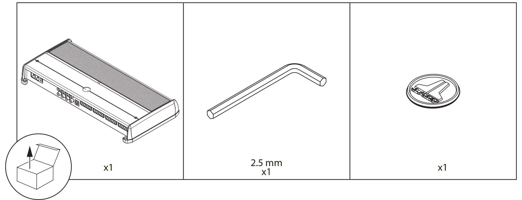
PARTS
INSTALLATION CONSIDERATIONS
- Installation requires appropriate tools and safety equipment. Professional installation is recommended.
- This product is water-resistant. Do not submerge or subject to high-pressure water spray.
- Before installation, turn off the audio system and disconnect the battery system from the audio system.
- When possible, install in a dry, well-ventilated location that does not interfere with factory installed systems. If a dry environment is not available, a location that is not exposed to heavy splashing may be used.
- Do not install in the engine compartment, any areas of extreme heat or where it will be directly exposed to the elements.
- Before cutting or drilling, check for potential obstacles behind mounting surfaces.
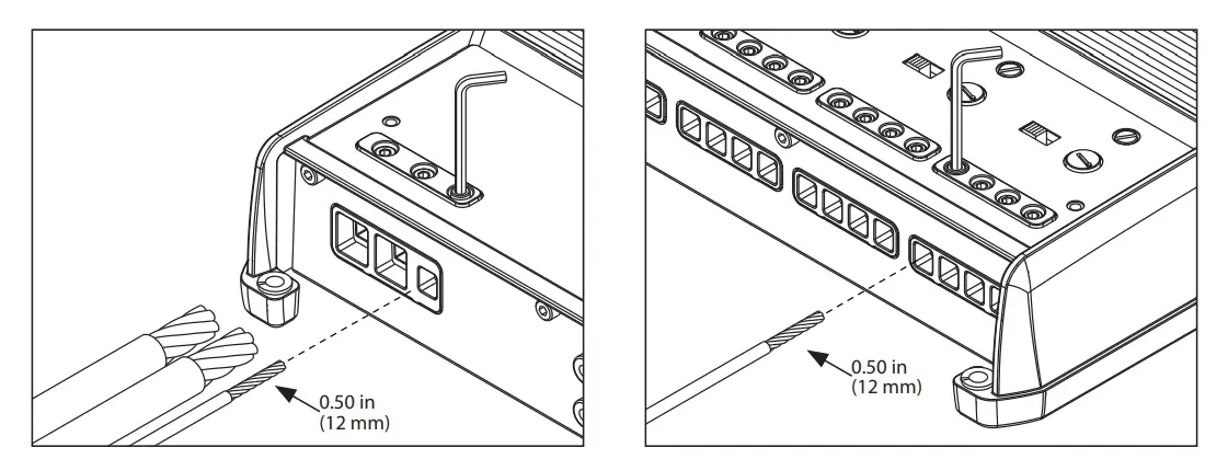
- Carefully route all system wiring away moving parts and sharp edges; secure with cable ties or wire clamps and use grommets and loom where appropriate to protect from sharp edges.
SAFETY CONSIDERATIONS
- Only use this product with 12 volt, negative round electrical systems. This product is not certified or approved for use in aircraft.
- Mount this product securely to prevent damage or injury in severe conditions.
- An appropriate fuse (or circuit breaker) at the main power wire is vital for vehicle/vessel safety and must be installed within 18 inches (45 cm) of the positive battery connection.
- For ABYC and NMEA applications, circuit protection is required within 7 inches (18 cm) of the battery, unless the cable is in an enclosure or conduit.
- Listen to your audio system at levels appropriate for operating conditions and hearing safety.
CONNECTIONS
| Connection | Description | Notes | |||
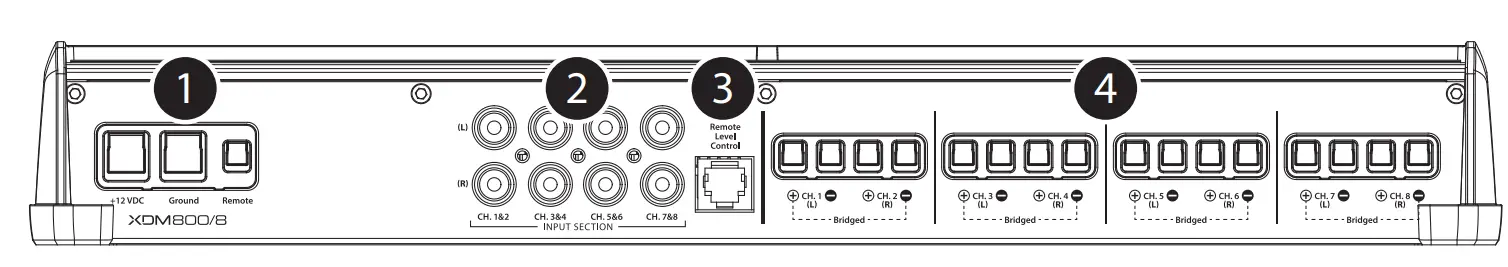
| 1 | +12 VDC | Positive (+12V) Power Connection |
| ||
| Ground | Negative (GND) Ground Connection |
| |||
| Remote | Positive (+12V) Activation Connection |
| |||
|
2 | CH. 1 Input | Left Input Signal, Black RCA |
| ||
| CH. 2 Input | Right Input Signal, Red RCA | ||||
| CH. 3 Input | Left Input Signal, Black RCA | ||||
| CH. 4 Input | Right Input Signal, Red RCA | ||||
| CH. 5 Input | Left Input Signal, Black RCA | ||||
| CH. 6 Input | Right Input Signal, Red RCA | ||||
| CH. 7 Input | Left Input Signal, Black RCA | ||||
| CH. 8 Input | Right Input Signal, Red RCA | ||||
| 3 | Remote Level Control | Remote Level Controller Connection (optional) (HD-RLC or MHD-RLC) |
| ||
| 4 | CH. 1 (L) Speaker Output |  | (+) Positive Speaker Output | CH. 1&2 Bridged (+) |
|
 | (–) Negative Speaker Output | ||||
| CH. 2 (R) Speaker Output | | (+) Positive Speaker Output | |||
| (–) Negative Speaker Output | CH. 1&2 Bridged (–) | |||
| CH. 3 (L) Speaker Output | | (+) Positive Speaker Output | CH. 3&4 Bridged (+) | ||
| (–) Negative Speaker Output | ||||
| CH. 4 (R) Speaker Output | | (+) Positive Speaker Output | |||
| (–) Negative Speaker Output | CH. 3&4 Bridged (–) | |||
| CH. 5 (L) Speaker Output | | (+) Positive Speaker Output | CH. 5&6 Bridged (+) | ||
| (–) Negative Speaker Output | ||||
| CH. 6 (R) Speaker Output | | (+) Positive Speaker Output | |||
| (–) Negative Speaker Output | CH. 5&6 Bridged (–) | |||
| CH. 7 (L) Speaker Output | | (+) Positive Speaker Output | CH. 7&8 Bridged (+) | ||
| (–) Negative Speaker Output | ||||
| CH. 8 (R) Speaker Output | | (+) Positive Speaker Output | |||
| (–) Negative Speaker Output | CH. 7&8 Bridged (–) | |||
| Control (Function) | Setting | Description | ||
| 5 | Status LED (indicates operating status) | Flashing Green | Amplifier Powering Up, Audio Output Muted | |
| Green | On-Normal Operation, Active Audio Output | |||
| Red | On-Safe Mode, Over-Temperature Condition, Audio Output Reduced
| |||
| Amber (yellow) | On-Safe Mode, Over-Current Condition, Audio Output Muted
| |||
| LEDs Off | Amplifier Turns Off (unexpectedly), Low-Voltage Condition
| |||
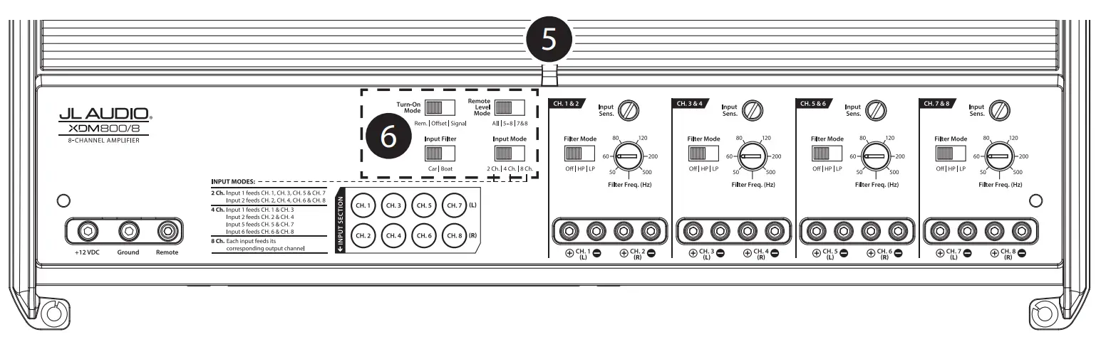
| 6 | Turn On Mode (configures activation method) | Remote | +12V Remote Turn-On (Preferred) • Controlled by a switched +12V circuit or turn-on output of your source unit/OEM interface | |
| Offset | DC Offset-Sensing (Automatic)
|
| ||
| Signal | Signal-Sensing (Automatic)
| |||
| Input Filter (configures input filter application) | Car | Select for most installations (automotive or marine) | ||
| Boat | Select if experiencing interference from high-current mechanical switches/devices | |||
| Input Mode (configures input signal connections) | 2 Ch. | Select when using CH. 1&2 inputs only
| ||
| 4 Ch. | Select when using CH. 1&2 and CH. 5&6 inputs
| |||
| 8 Ch. | Select when using all eight inputs | |||
| Remote Level Mode (configures HD-RLC operation – optional) | All | Adjusts level of all channels equally |
| |
| 5 – 8 | Adjusts level of channels 5, 6, 7 & 8 only | |||
| 7 & 8 | Adjusts level of channels 7 & 8 only | |||
| Control (Function) | Setting | Description | ||
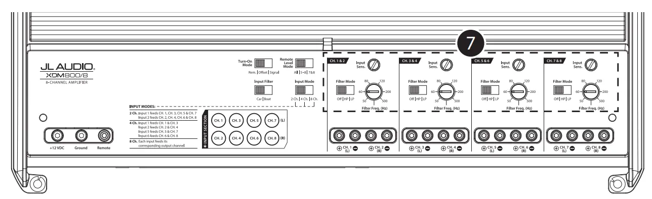
| 7 | Input Sens. adjusts each channel pair’s input stage) | Variable | Use to match the source unit’s output voltage with the inputs of each pair of amplifier channels. See Appendix A for detailed information. | |
| CH. 1&2 | Filter Mode (configures the filter of CH. 1&2) | Off | Filter defeated; passes full range of frequencies present at the inputs | |
| HP | Attenuates frequencies below the CH. 1&2 “Filter Freq. (Hz)” dial, at a rate of 12dB/octave | |||
| LP | Attenuates frequencies above the CH. 1&2 “Filter Freq. (Hz)” dial, at a rate of 12dB/octave | |||
| Filter Freq. (Hz) (adjusts filter cutoff frequency) | Variable | Use to adjust the cutoff frequency of channel 1&2’s active filter, from 50 Hz – 500 Hz / 12dB per octave | ||
| CH. 3&4 | Filter Mode (configures the filter of CH. 3&4) | Off | Filter defeated; passes full range of frequencies present at the inputs | |
| HP | Attenuates frequencies below the CH. 3&4 “Filter Freq. (Hz)” dial, at a rate of 12dB/octave | |||
| LP | Attenuates frequencies above the CH. 3&4 “Filter Freq. (Hz)” dial, at a rate of 12dB/octave | |||
| Filter Freq. (Hz) (adjusts filter cutoff frequency) | Variable | Use to adjust the cutoff frequency of channel 3&4’s active filter, from 50 Hz – 500 Hz / 12dB per octave | ||
| CH. 5&6 | Filter Mode (configures the filter of CH. 5&6) | Off | Filter defeated; passes full range of frequencies present at the inputs | |
| HP | Attenuates frequencies below the CH. 5&6 “Filter Freq. (Hz)” dial, at a rate of 12dB/octave | |||
| LP | Attenuates frequencies above the CH. 5&6 “Filter Freq. (Hz)” dial, at a rate of 12dB/octave | |||
| Filter Freq. (Hz) (adjusts filter cutoff frequency) | Variable | Use to adjust the cutoff frequency of channel 5&6’s active filter, from 50 Hz – 500 Hz / 12dB per octave | ||
| CH. 7&8 | Filter Mode (configures the filter of CH. 7&8) | Off | Filter defeated; passes full range of frequencies present at the inputs | |
| HP | Attenuates frequencies below the CH. 7&8 “Filter Freq. (Hz)” dial, at a rate of 12dB/octave | |||
| LP | Attenuates frequencies above the CH. 7&8 “Filter Freq. (Hz)” dial, at a rate of 12dB/octave | |||
| Filter Freq. (Hz) (adjusts filter cutoff frequency) | Variable | Use to adjust the cutoff frequency of channel 7&8’s active filter, from 50 Hz – 500 Hz / 12dB per octave | ||
APPENDIX A
Input Sensitivity Level Setting
Follow the steps below to adjust the input sensitivity of each amplifier channel pair to achieve overall system balance.
| Necessary Equipment |
Full range channel/amplifier applications: 1 kHz Subwoofer channel/amplifier applications: 50 Hz
|
| The Nine-Step Procedure |
| 1. Disconnect the speaker(s) from the amplifier’s speaker output connectors. |
| 2. Turn off all processing (bass/treble, loudness, EQ, etc.) on the source unit, processors (if used) and amplifier. Set the fader control to center position and the subwoofer level control to 3/4 of maximum, if used. |
| 3. Turn all “Input Sens.” controls all the way down. |
| 4. Set the source unit volume to 3/4 of full volume. This will allow for reasonable gain overlap with moderate clipping at full volume. |
| 5. Using the chart below, determine the target voltage for input sensitivity adjustment according to the nominal impedance of the speaker system connected to the amplifier outputs. |
| 6. Verify that you have disconnected the speakers before proceeding. Play a track with an appropriate sine wave (within the frequency range to be amplified) at 3/4 source unit volume. |
| 7. Connect the AC voltmeter to the speaker output terminals of the amplifier. If the channel pair is operating in stereo, it is only necessary to measure one channel. If bridged, make sure you test the voltage at the correct terminals (L+ and R–). |
| 8. Increase the “Input Sens.” control until the target voltage is observed with the voltmeter. |
| 9. Once you have adjusted each channel section to its maximum low-distortion output level, reconnect the speaker(s). The “Input Sens.” controls can now be adjusted downward if the amplifier requires attenuation to achieve the desired system balance. |
| IMPORTANT! |
|
|
| Nominal Impedance | Target AC Voltage | |
| Stereo | Bridged | |
| 8Ω | 17.3 V | 34.6 V |
| 4Ω | 17.3 V | 28.3 V |
| 3Ω | 16.0 V | not recommended |
| 2Ω | 14.1 V | not recommended |
SPECIFICATIONS
| Amplifier Section | ||||
| Amplifier Topology | NexD™ Ultra-High Speed Class D | |||
| Power Supply Type | Unregulated MOSFET Switching | |||
| Minimum Copper Power/GND Wire | 4 AWG (Note: CCA/Copper Clad Aluminum wire is not recommended.) | |||
| Recommended Fuse | 80 A | |||
| Rated RMS Power @ 14.4V, <1% THD+N | 75W x 8 @ 4 Ω | 100W x 8 @ 2 Ω | ||
| 150W x 4 @ 8 Ω Bridged | 200W x 4 @ 4 Ω Bridged | |||
| Rated RMS Power @ 12.5V, <1% THD+N | 60W x 8 @ 4 Ω | 90W x 8 @ 2 Ω | ||
| 120W x 4 @ 8 Ω Bridged | 180W x 4 @ 4 Ω Bridged | |||
| Frequency Response | 12 Hz – 22 kHz (+0, -1dB) | |||
| S/N Ratio (A-weighted, 20 Hz–20 kHz noise bandwidth) | >104 dB (Referred to rated power), >84 dB (Referred to 1W) | |||
| Damping Factor | >150 / 50 Hz @ 4 Ω, >75 / 50 Hz @ 2 Ω | |||
| Input Section | ||||
| Number of Inputs | 8 (Four Stereo Pairs) | |||
| Input Type | Differential-Balanced with RCA jack inputs | |||
| Input Voltage Range | 200mV – 4V RMS | |||
| Signal Processing | ||||
| Filter Type | CH. 1&2 | CH. 3&4 | CH. 5&6 | CH. 7&8 |
| Active, 12dB/octave, High-Pass or Low-Pass (50 – 500 Hz), defeat able | ||||
| Remote Level Control | HD-RLC or MHD-RLC (optional). Full mute to 0 dB range. | |||
| Dimensions | ||||
| L x W x H | 14.73 in. x 7.09 in. x 2.05 in. (374 mm x 180 mm x 52 mm) | |||
Due to ongoing product development, all specifications are subject to change without notice.