acer K272HL Monitor Lifecycle Extension User Guide
Important Safety Notice
Product Announcement:
This product is certificated to meet RoHS Directive and Lead-Free produced definition. Using approved critical components only is recommended when the situation to replace defective parts. Vender assumes no liability express or implied, arising out of any unauthorized modification of design or replacing non-RoHS parts. Service providers assume all liability
Qualified Repairability:
Proper service and repair is important to the safe, reliable operation of all series products. The service providers recommended by vender should being aware of notices listed in this service manual in order to minimize the risk of personal injury when perform service procedures. Furthermore, the possible existed improper repairing method may damage equipment or products. It is recommended that service engineers should have repairing knowledge, experience, as well as appropriate product training per new model before performing the service procedures.
NOTICE:
- To avoid electrical shocks, the products should be connect to an authorized power cord, and turn off the master power switch each time before removing the AC power cord.
- To prevent the product away from water or explosed in extremely high humility environment.
- To ensure the continued reliability of this product, use only original manufacturer’s specified parts.
- To ensure following safety repairing behavior, put the replaced part on the components side of PWBA, not solder side.
- To ensure using a proper screwdriver, follow the torque and force listed in assembly and disassembly procedures to screw and unscrew screws.
- Using Lead-Free solder to well mounted the parts.
- The fusion point of Lead-Free solder requested in the degree of 220°C.
Exploded Diagram
Product Exploded Diagram
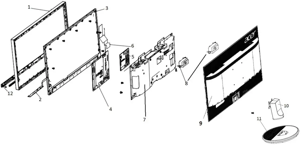
INDEX | DESCRIPTION |
1 | MID-FRAME |
2 | PCBA CTRL BD |
3 | LCDM 27W AUO M270HVN02.3Q0 Z |
4 | PCBA SPS BD |
5 | PCBA IF BD |
6 | FFC LVDS 30P P1 B276HL |
7 | ASSY SHD AH1 1A1D1H+SPK V276HL |
8 | #SPK*2 2.5W 4OHM 320/320MM |
9 | ASSY RC 1A1D1H+SPK DB22A V276H |
10 | ASSY CLMN K272HL |
11 | ASSY BASE K272HL |
| 12 | ASSY TRIM K272HL |
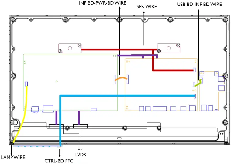
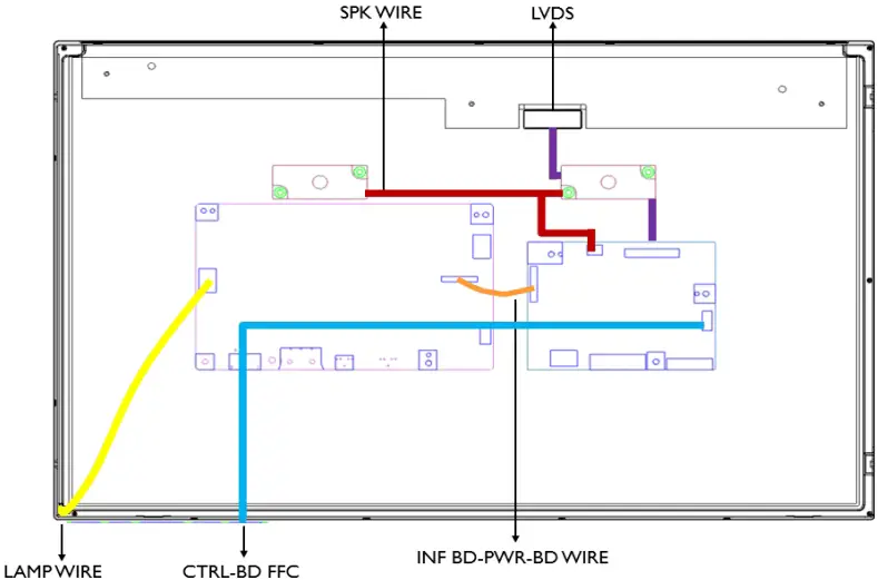
Wiring connectivity diagram
There are four types of wiring diagrams for model K272HL. The wiring connectivity position will be different according to the ACTUAL PCBA connector position. Please base on different SKU refer to below diagram.
NOTE: INF BD= Interface Board, PWR BD=Power Board, CTRL BD= Control Board
- SKU with USB

- . SKU without USB

Mechanical Instruction
Tools Required
List the type and size of the tools that would typically can be used to disassemble the product to a point where components and materials requiring selective treatment can be removed.
Tool Description:
- working table
- Screw-driver: Philips-head screwdriver, Hex-head screwdriver
- Knife
- glove
- cleaning cloth
- ESD protection
Disassembly and Assembly SOP
K272HL
Disassembly Procedures | |
Preparation before disassemble
| |
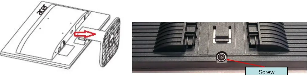
| S1 Disassemble the RC(Rear Case), stand and base | Before Disassembling & Assembling, monitor need to be put on the sponge and the Insulation glove must be wore during the process. Disassemble Stand and Base from the RC(Rear Case). Unlock RC screws. Disassemble RC from monitor. |
 | |
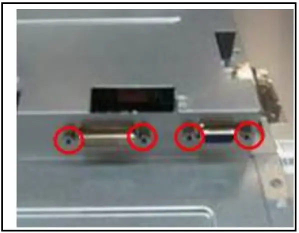
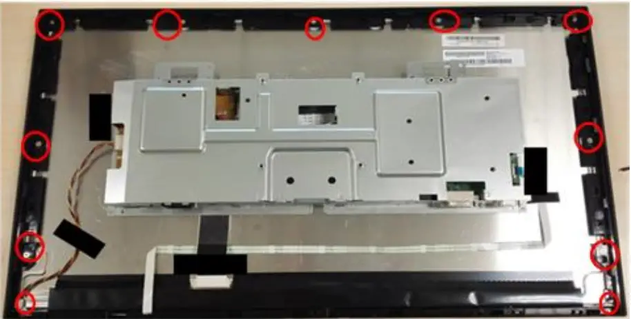
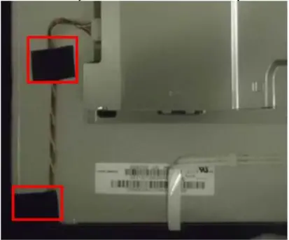
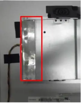
| S2 Disassemble SHD and MF | Tear down AL-Tape off SHD(Shielding) as picture 1. Unlock the Hexagonal screws as picture 2. Unlock 9 MF screws and 2 trim screws as picture 3. |
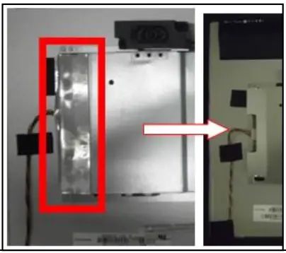   | |
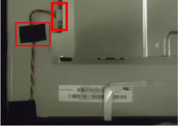
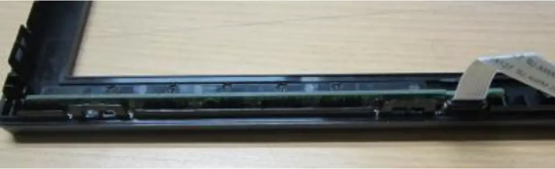
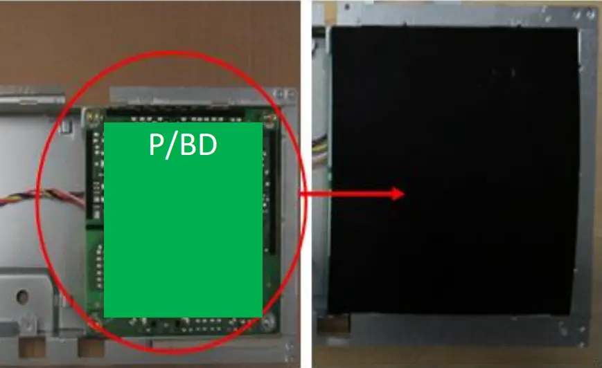
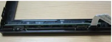
| S3 Disassemble the lamp wire | Tear off the tape on the lamp wire and etract the lamp wire form the P/BD(Power Board) as the picture |
 | |
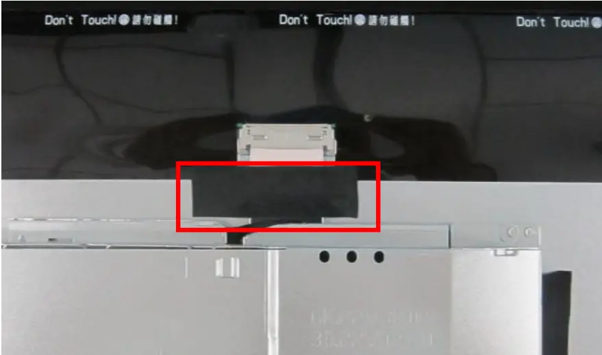
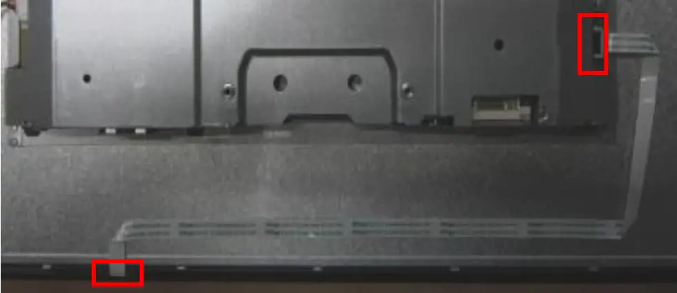
| S4 Disassemble LVDS cable and CTRL BD | Tear off the tape, pull out the FFC as picture 1. Pull the CTRL BD-FFC out of the PCBA and the CTRL BD, tear off the tape and disassemble the CTRL BD-FFC |
  | |
| S5 Disassemble the Bezel from panel. | Tear off the tapes, take out the Panel and the CTRL BD of the Bezel |
 | |
| S6 Disassemble I/F BD and P/BD from SHD. | Disassembled the Mylar and unlock all screws. Disassemble the I/F BD from the SHD and extract the P/BD wire. Extract the FFC LVDS from the I/F BD. Disassemble the P/BD from the SHD. |
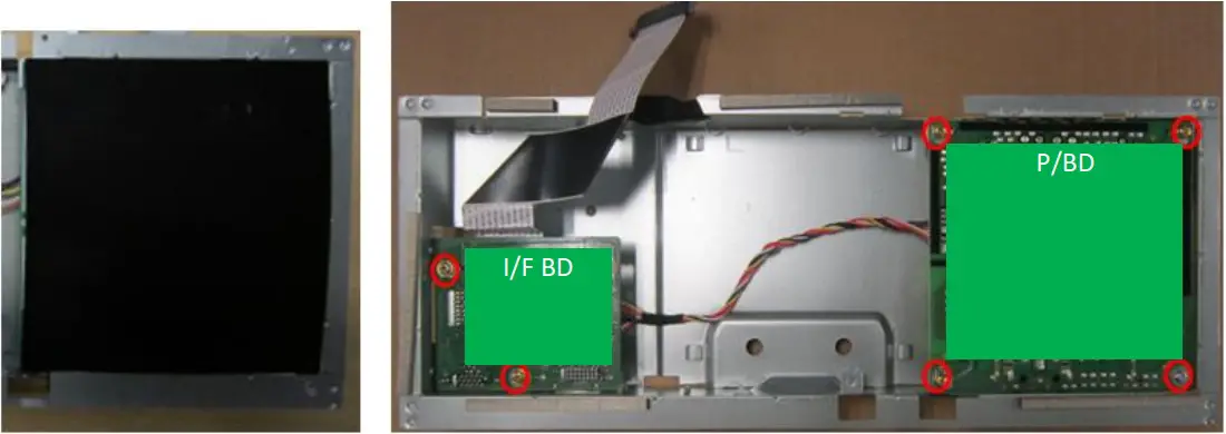 | |
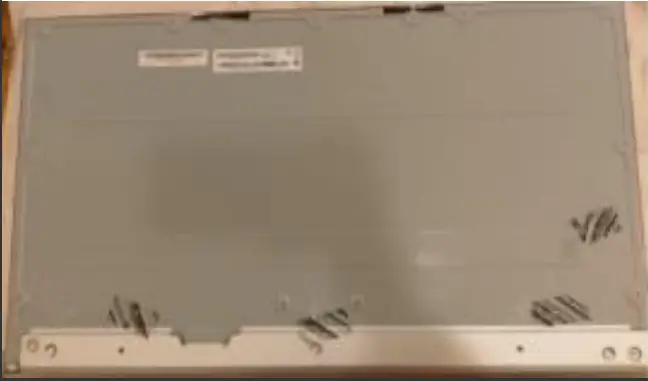
![]() NOTE: Circuit boards >10 cm² has been highlighted with the yellow rectangle as above image shows. Please detach the Circuit boards and follow local regulations for disposal.
NOTE: Circuit boards >10 cm² has been highlighted with the yellow rectangle as above image shows. Please detach the Circuit boards and follow local regulations for disposal.
Assembly Procedures | |
Preparation before disassemble
| |
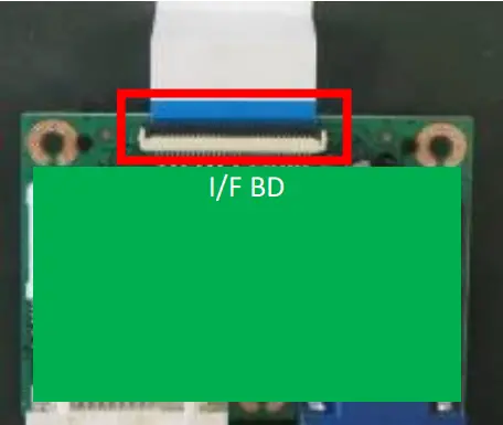
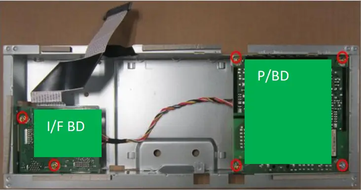
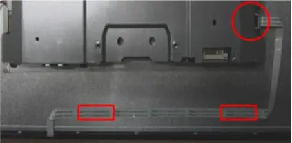
| S1 Assemble I/F BD and P | Before Disassembling & Assembling, monitor need to be put on the sponge and the Insulation glove must be wore during the process. Insert the FFC to the I/F. Insert the P/BD-Wire to the I/F BD and the P/BD. Place the I/F BD and the Power BD to main SHD. stick one tape on the SHD remarked with red circle and lock all screws as the picture. Put Mylar on the Power BD |
   | |
| S2 Assemble MF and Panel | ake the Panel and insert lamp wire to panel Assemble the MF to the panel ,and lock 9 screws to the MF as the picture |
PICTURE 1 | |
| S3 Assemble SHD | Lock the Hexagonal screws as picture 1. Use jig to put the SHD in correct position on Panel. Take off the jig and stick two AL tapes as picture 2 |
PICTURE 1 PICTURE 2 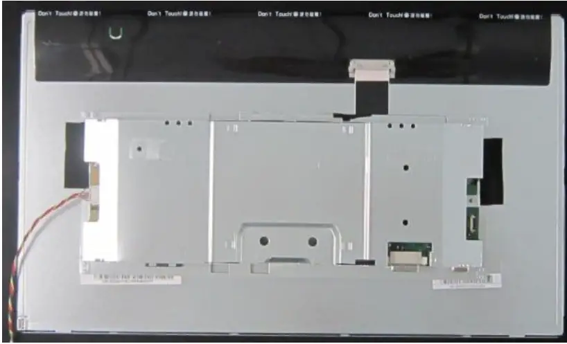 Note: please refer to Appendix for the jig and select “None” for page scaling item 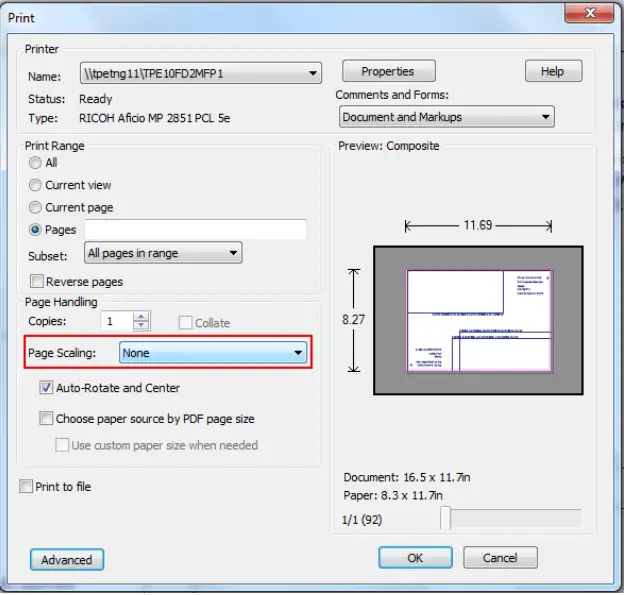 | |
| S4 Assemble LVDS cable | Insert the LVDS cable to the Panel and stick one tape on LVDS cable |
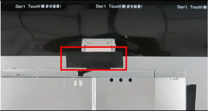 | |
| S5 Assemble the lamp wire | Insert the lamp wire to the P/BD . Stick 2 tape to fasten the lamp wire and one AL-Tape on SHD as the picture. |
  | |
| S6 Assemble CTRL-BD | Insert the CTRL BD-FFC to CTRL BD as circle frame, and insert them into the bezel. Assemble the panel on the bezel. Stick Mylar on CTRL BD FFC as square frame and Insert the CTRL BD -FFC to the PCBA as circle frame. |
  | |
| S7 Assemble RC, stand and base | Assemble the RC with screw. Assembly the Stand and the Base to Monitor |
PICTURE 1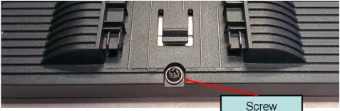 PICTURE 2 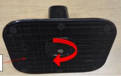 PICTURE 3 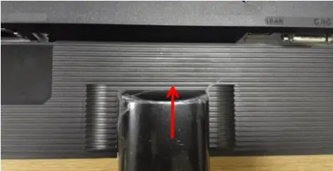 | |
Troubleshooting
TROUBLESHOOTING
Before sending your LCD monitor for servicing, please check the trouble-shooting list below to see if you can self-diagnose the problem.
(VGA Mode)
Problems | Curren! Slays | Remedy |
No Picture | LEO ON |
|
| LEO OFF |
| |
| ||
| LED displays amber cola |
| |
| ||
Abnormal Picture | Unstable picture |
|
| Display is missing, center shift, or too small or too large in display size |
| |
| ||
Abnormal Sound (Only Audio-Input model) (Optional) | No sound, or sound level is too low | Check the audio cable with the host PC is connected. |
| Check if the volume setup of the host PC is in minimum position and try to raise the volume level |
(HDMI/DP Mode)
| Problems | Current Status | Remedy |
| No Picture | LED ON |
|
| LED OFF |
| |
| ||
| LED displays amber color |
| |
| ||
| Abnormal Sound (Only Audio-Input model) (Optional) | No sound, or sound level is too low | Check the audio cable with the host PC is connected. |
| Check if the volume setup of the host PC is in minimum position and try to raise the volume level. |
FRU List
This chapter gives you the FRU (Field Replaceable Unit) listing in global configurations of ACER K272HL. Refer to this chapter whenever ordering for parts to repair or for RMA (Return Merchandise Authorization).
Please note that WHEN ORDERING FRU PARTS, you should c heck the most up-to-date information available on your regional web or channel. For whatever reasons a part number change is made, it will not be noted on the printed Service Guide. For AUTHORIZED SERVICE PROVIDERS, your office may have a DIFFERENT part number code from those given in the FRU list of this printed Service Guide. You MUST use the local FRU list provided by your regional office to order FRU parts for repair and service of customer machines
NOTE: To scrap or to return the defective parts, you should follow the local government ordinance or regulations on how to dispose it properly, or follow the rules set by your regional office on how to return it.
| Category | ACER DESCRIPTION | Description | PART NO. |
 | LED LCD Panel AUO 27’H FHD None Glare M270HVN02.3 Q0-Z19 LF 300nit 12ms VA | LCDM 27W AUO M270HVN02.3Q0 Z | KL.27005.021 |
| BOARD | |||
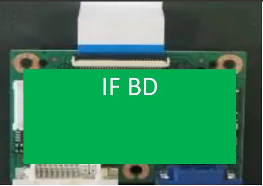 | MAIN BD | PCBA IF BD MI VA270H AUO H+S | 55.T5UM3.001 |
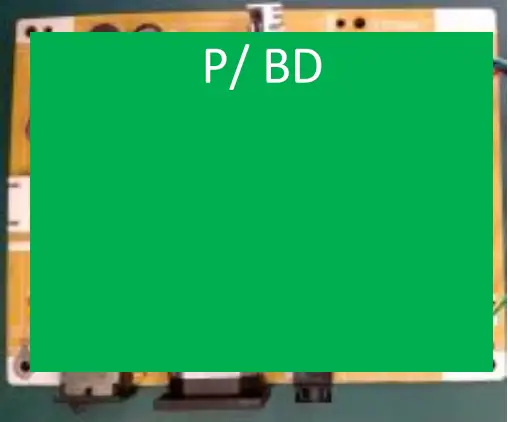 | POWER BD | PCBA SPS BD MI H+S V276HL AUO | 55.T5UM3.002 |
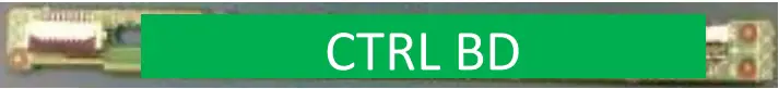 | CONTROL BOARD | PCBA CTRL BD SMD B276HL | 55.T4HM3.003 |


