
 Interface Manual
A2 HART
SignalFire Model: A2-HART-XXXX
The SignalFire A2-HART Node has the following features:
- HART communication loop. Supports up to 4 HART devices, reads up to 4 process variables from each connected HART device.
- Provides 18VDC to HART communication loop.
- One counter/frequency inputs, up to 2kHz. Open drain or pulse input supported
- Reports state of dry contact inputs, open/closed.
- One 32Bit count totalizer
- Low power operation from a 3 “D” cell lithium battery pack or A2-HCSolar system (external power from 3.5 to 5.0VDC may be used in place of the battery)
- Sends data to a SignalFire Buffered Modbus Gateway
- AES128bit Encryption
- Remote configuration and remote PACTware/Radar Master support
Specifications
| Enclosure Size | 7.0” tall × 4.25” wide × 3.0” deep (not including attached antenna) |
| Power Source | Internal Lithium battery pack SignalFire Part Number: Bat-3XD Solar battery system SignalFire Part Number: IQSB-2XD-Solar |
| Temperature Rating | -40°C to +85°C |
| Radio Frequency | 500mW, 902-928MHz ISM Band, FHSS radio |
| Compliance | FCC Part 15 compliant radio |
Connections and Components
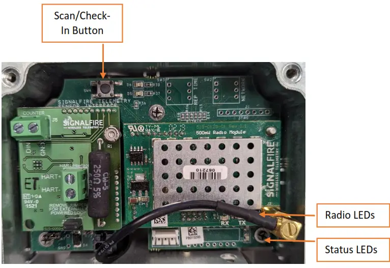
Radio LEDs
– The Radio TX LED (green) flashes each time a radio packet is sent. This LED will blink rapidly while searching for the radio network.
– The Radio RX LED (red) blinks on each received radio packet.
Status LEDs
– The Active LED (green) will blink at boot up and will blink rapidly when the sensor is being powered.
– The ERROR LED (red) will blink to indicate an error condition.
Scan/Checkin Button
– If this button is pressed the A2will apply power to the sensor for the configured sensor on time and scan for the HART sensor. If the Hart sensor is detected the HART_STATUS LED will blink once and its data will be read. The A2 will also send the collected sensor data to the gateway.
Setup
The nodes need to be set up for correct operation before being fielded. The configurable items include:
– Network selection
– Encryption Settings
– Check-in period selection
– Modbus Slave ID setting
– Sensor on time
Settings are made using the SignalFire Toolkit PC application and a serial programming cable.
For legacy devices that have the rotary and DIP switches installed, the Modbus Slave ID can also be set using the switches.
Using the SignalFire Toolkit
The SignalFire Toolkit application can be downloaded at www.signal-fire.com/customer. After installation, launch the software and the main toolkit window will open:
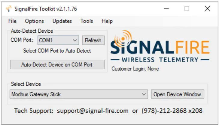 Select the COM port associated with the A2 Node and click “Auto-Detect Device on COM Port.” This will open the device configuration window, where all device settings can be configured.
Network Setting
The network is set using the SignalFire Toolkit. The network, network group, and Encryption Key/Corporate ID settings must match those of the gateway (and other nodes) in order for them to communicate. For legacy devices that have the rotary switches installed, the network is set using rotary switch SW2 on the upper right of the board. If set to zero then the network can be set using the ToolKit software.
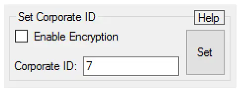
Encryption
Starting with A2 version r72, it is possible to encrypt over-the-air transmissions to prevent tampering.
Encryption keys replace the Corporate ID system, so it is important that all devices connected to a Gateway have the same encryption key as well as network and network group number. To set up a node to use encryption, click the checkbox labeled Enable Encryption inside the Set Corporate ID box:
 The encryption key box. For more details, click the Help button.
The box will then change into a Set Encryption Key box, and it will prompt instead for the encryption key you would like to use. Note that keys may not contain spaces or angle brackets. Enter it and then press Set. This will cause the node to drop its network, and only attempt to join networks that use the same encryption key. If you are setting up a new network, you will need to set the encryption key on all of your devices. If you are adding a node to a legacy network, you can simply set the Corporate ID without clicking the Enable Encryption box, it will remain compatible with the older system.
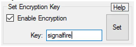 Setting the encryption key.
It is also possible to hide your encryption key so it cannot be read. This is the most secure option, but if you forget your key, there is no way to recover it – you have to reset the key on every device on its network. To enable this option, select Set Encryption Key Unrecoverable under the Settings menu.
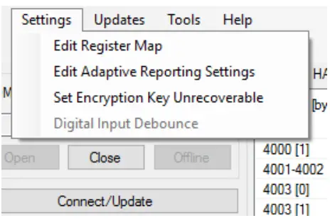 Setting the encryption key to be unrecoverable.
Modbus Slave ID
The Modbus Slave ID can be set with the SignalFire Toolkit, or with the DIP switch located on legacy devices.
The DIP switch takes an 8-bit binary input which is converted into a slave ID from 1 to 240. In the picture
below switch 1 and 2 are on, which is 00000011 and results in a slave ID of 3.
The least significant bit (LSB)
is on the right and is labeled 1 above the row of switches. The A2 must be power cycled after setting the DIP switch.
Note: The DIP switch must be set to 0 (all switches off) in order to set the Slave ID with the SignalFire Toolkit.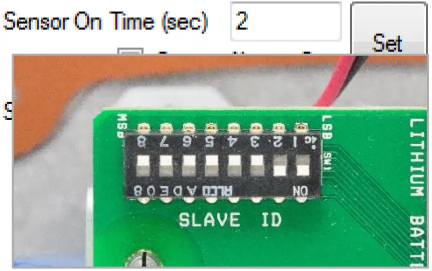
Sensor Settings
The A2-HART Node will supply 18 volts to the sensor. The sensor warm-up time must also be configured. The default is 2 seconds which is used for most pressure and other simple sensors. Radar sensors often require a longer warm-up time. Contact your sensor manufacturer or SignalFire for details.
Check-In Interval
The check-in period is set using the SignalFire ToolKit.
For legacy devices that have the rotary switch SW1 in the upper right corner of the board, the check-in can be set using the switch. If set to position 0 the check-in interval can be configured using the ToolKit. The switch settings are shown in the following table:
| Switch Setting | Check-In Period |
| 0 | 1 min |
| 1 | 2 min |
| 2 | 4.5 min |
| 3 | 10 min |
| 4 | 30 min |
| 5 | 1 hr |
| 6 | 5 sec |
| 7 | 15 sec |
The default setting is 2 for a check-in period of 4.5 minutes.
Note: Settings 6 and 7 should only be used for testing or a non-battery pack-powered node as they will have a high power draw.
HART Sensor Connections
Wiring A HART sensor may then be connected to the system using the screw terminal connector on the connector daughterboard. HART sensors using the two HART terminals as shown in the following diagram: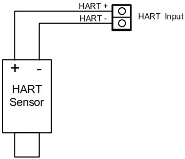
Up to 3 additional HART sensors may be daisy-chained in parallel.
The system will supply a minimum of 18 Volts to the sensors for 2 seconds (by default) and then read the HART data from each sensor. If 4 HART devices are connected the total loop current will be 16mA, resulting in 4V being dropped across the 250-ohm load resistor in the SignalFire node. This leaves 14V available to power the sensors.
Upon initial power-up, the SignalFire HART node will poll for HART devices addressed 1 through 4, to discover which nodes are connected. The node will read the Manufacturer and device ID for each discovered sensor and send this value to the gateway at each check-in. Also, the node will blink the green LED, D6 for each HART sensor that is detected. For example, if HART sensor IDs 2 and 4 are connected, D6 will blink twice, pause, and then blink four times.
To manually run the HART discovery process and force a check-in to the gateway, simply press switches SW4. The discovery process will be re-run automatically every 100 check-ins to see if any new nodes have been added to the loop.
Externally powered HART loop
If the HART loop is to be powered externally, remove jumper J3 from the HART card and configure the sensor on time to 0 seconds using the ToolKit. Connect the HART+ and HART- terminals in parallel to the HART devices. Note that in this configuration the 250ohm HART resistor must be installed in the loop as the 250ohm resistor on the A2 is no longer in series with the loop.
HART Sensor Configuration
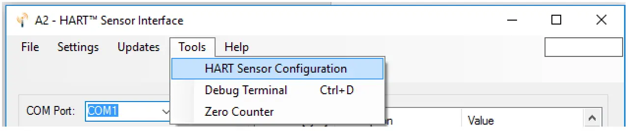
The A2 requires that the attached HART sensor is configured to HART ID 1, 2, 3, or 4 in “multi-drop” mode. The
sensor may be configured using a HART modem, or built-in display/buttons. Alternatively, the A2 provides tools that allow the HART ID of the attached sensor to be changed. To set the HART ID, go to the Tools dropdown menu and select HART Sensor Configuration.
If the sensor is not set to Sensor Always On, first click the large button to power the sensor for configuration.
Each click will power the sensor for 5 minutes, or until turned off. If the attached sensor has a warm-up time wait until the sensor is fully powered on before the next step.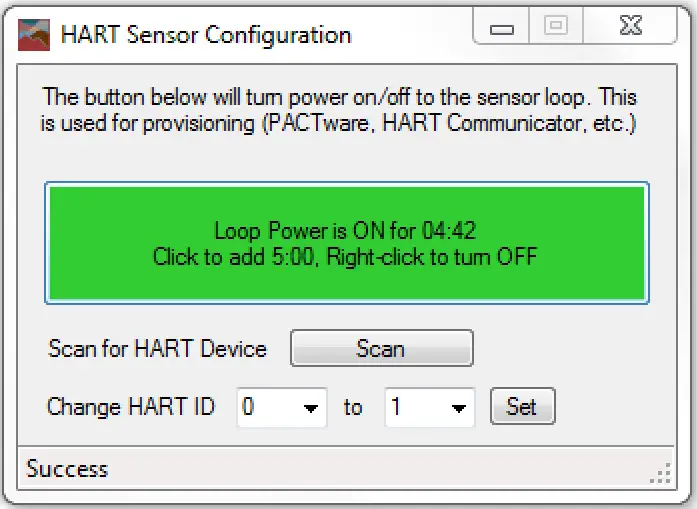
To change the HART ID the initial ID must be known. To find the ID, click Scan. Most sensors default to 0. To change the ID select the existing ID on the left, select 1, 2, 3 or 4 on the right, and click the Set button. If only a single HART device is connected it should be configured as HART ID 1.
Digital Input
The counter input may be either open collector type (sinking ground), dry contact inputs, or voltage pulse (up to 15V) type. The input can count up to 2000 Hz.
The counter input may be connected to the board as shown in the following diagrams:
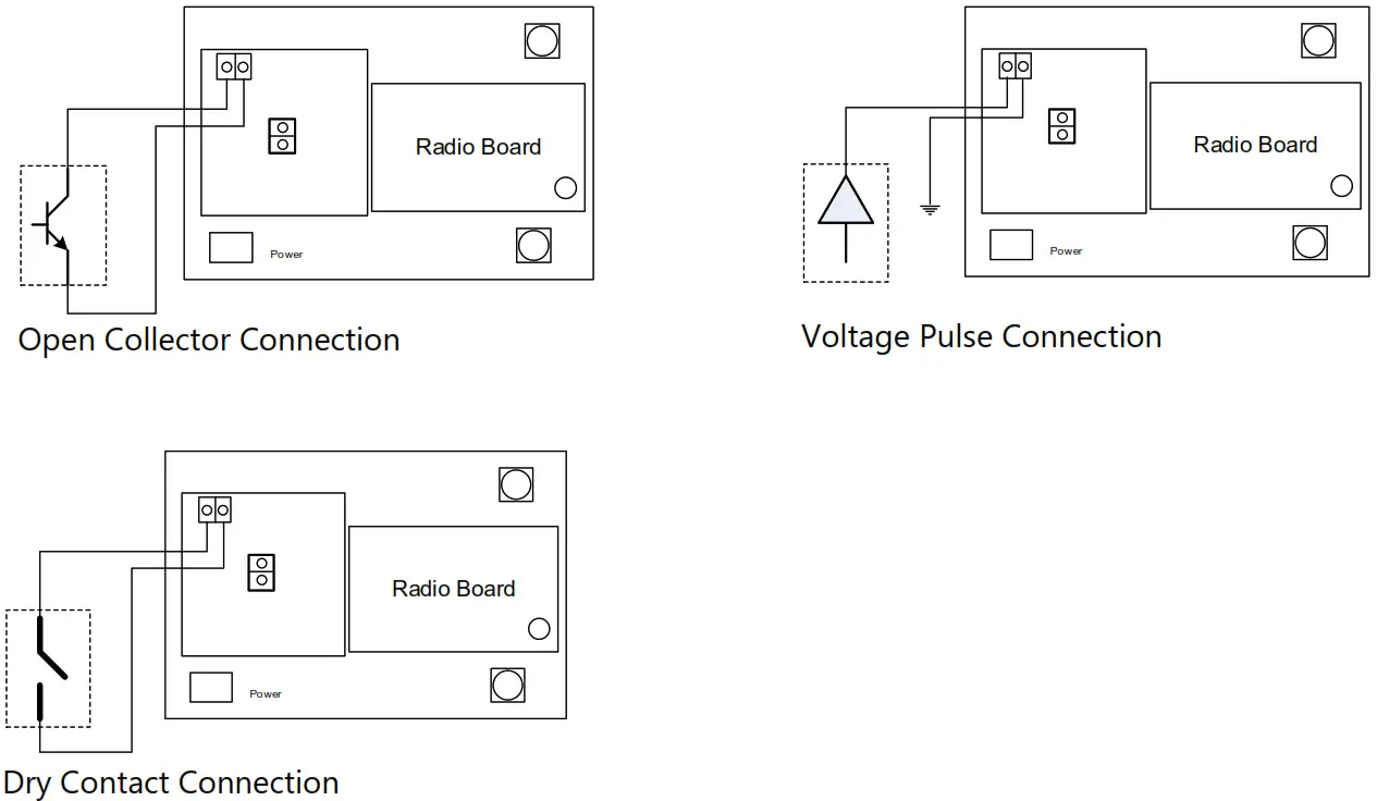
The count accumulates and the current count is stored into non-volatile memory. If the system is reset the counts will revert to the last stored value from the non-volatile memory. The system also reports the state of the contact closure input at the time of check-in.
Digital Input Debounce
In cases where it is desired to accurately totalize digital input counts, it may be necessary to enable the digital input debounce timer. The debounce timer is useful when dealing with dry contacts that may otherwise produce extra counts when they close. To enable the digital debounce, open the configuration window for the node in the SignalFire Toolkit and select Digital Input Debounce from the Settings menu. A typical value for a dry contact would be 100mS. Any extra counts due to contact bounce within the bounce time setting will be ignored.
Remote Modbus Register Mapping
The A2-HART sends data to a SignalFire Telemetry Modbus Gateway. The data that is sent to the gateway is available at the gateway in registers where it can then be read by a Modbus RTU.
Consequently, the node needs to have a unique (to the network it is in) Modbus slave ID which the gateway will use to store its unique data.
Modbus Registers
Every check-in period, the sensor(s) are read and data is sent to the gateway. The gateway will save the data under the set Modbus ID in 16-bit registers. If a HART device does not return all four variables, the ‘units code’ and variable register values will be set to 0 for any unreturned values.
The register map for this system is below.
Register Map
| Register Number | Register Address (Offset) | Description |
| 41004 | 1003 | Digital Input state (1=closed, 0=open) |
| 41005-41006 | 1004-1005 | 32-bit Hardware counter, 1004=high word |
| 41007 | 1006 | Average frequency over the last check-in period times 10 |
| 41012 | 1011 | Ave. counts per minute over the check-in period times 10 |
| 41013 | 1012 | Frequency over 2 seconds at check-in time times 10 |
| 42001 | 2000 | HART ID 1: Manufacturer’s ID Code/Device Type (ID=MSB, Device=LSB) |
| 42002 | 2001 | HART ID 1: Device ID Number (ID high bite = MSB, ID mid byte = LSB) |
| 42003 | 2002 | HART ID 1: Device ID Number, HART Status (ID low byte=MSB, Status=LSB) |
| 42004 | 2003 | HART ID 1: PV & SV Units Code (PV=MSB, SV=LSB) |
| 42005 | 2004 | HART ID 1: TV & QV Units Code (TV=MSB, QV=LSB) |
| 42006-42007 | 2005-2006 | HART ID 1: Primary Variable (PV) (two registers) (float) |
| 42008-42009 | 2007-2008 | HART ID 1: Secondary Variable (SV) (two registers) (float) |
| 42010-42011 | 2009-2010 | HART ID 1: Tertiary Variable (TV) (two registers) (float) |
| 42012-42013 | 2011-2012 | HART ID 1: Quaternary Variable (QV) (two registers) (float) |
| 42014 | 2013 | HART ID 2: Manufacturer’s ID Code/Device Type (ID=MSB, Device=LSB) |
| 42015 | 2014 | HART ID 2: Device ID Number (ID high bite = MSB, ID mid byte = LSB) |
| 42016 | 2015 | HART ID 2: Device ID Number, HART Status (ID low byte=MSB, Status=LSB) |
| 42017 | 2016 | HART ID 2: PV & SV Units Code (PV=MSB, SV=LSB) |
| 42018 | 2017 | HART ID 2: TV & QV Units Code (TV=MSB, QV=LSB) |
| 42019-42020 | 2018-2019 | HART ID 2: Primary Variable (PV) (two registers) (float) |
| 42021-42022 | 2020-2021 | HART ID 2: Secondary Variable (SV) (two registers) (float) |
| 42023-42024 | 2022-2023 | HART ID 2: Tertiary Variable (TV) (two registers) (float) |
| 42025-42026 | 2024-2025 | HART ID 2: Quaternary Variable (QV) (two registers) (float) |
| 42027 | 2026 | HART ID 3: Manufacturer’s ID Code/Device Type (ID=MSB, Device=LSB) |
| 42028 | 2027 | HART ID 3: Device ID Number (ID high bite = MSB, ID mid byte = LSB) |
| 42029 | 2028 | HART ID 3: Device ID Number, HART Status (ID low byte=MSB, Status=LSB) |
| 42030 | 2029 | HART ID 3: PV & SV Units Code (PV=MSB, SV=LSB) |
| 42031 | 2030 | HART ID 3: TV & QV Units Code (TV=MSB, QV=LSB) |
| 42032-42033 | 2031-2032 | HART ID 3: Primary Variable (PV) (two registers) (float) |
| 42034-42035 | 2033-2034 | HART ID 3: Secondary Variable (SV) (two registers) (float) |
| 42036-42037 | 2035-2036 | HART ID 3: Tertiary Variable (TV) (two registers) (float) |
| 42038-42039 | 2037-2038 | HART ID 3: Quaternary Variable (QV) (two registers) (float) |
| 42040 | 2039 | HART ID 4: Manufacturer’s ID Code/Device Type (ID=MSB, Device=LSB) |
| 42041 | 2040 | HART ID 4: Device ID Number (ID high bite = MSB, ID mid byte = LSB) |
| 42042 | 2041 | HART ID 4: Device ID Number, HART Status (ID high byte=MSB, Status=LSB) |
| 42043 | 2042 | HART ID 4: PV & SV Units Code (PV=MSB, SV=LSB) |
| 42044 | 2043 | HART ID 4: TV & QV Units Code (TV=MSB, QV=LSB) |
| 42045-42046 | 2044-2445 | HART ID 4: Primary Variable (PV) (two registers) (float) |
| 42047-42048 | 2046-2047 | HART ID 4: Secondary Variable (SV) (two registers) (float) |
| 42049-42050 | 2048-2049 | HART ID 4: Tertiary Variable (TV) (two registers) (float) |
| 42051-42052 | 2050-2051 | HART ID 4: Quaternary Variable (QV) (two registers) (float) |
| 42053 | 2052 | Bitmap of the Sensors Read in Last Check-in |
| 49987 | 9986 or 65523 | Low Battery Alarm (0 = battery above 3.0V, 1 = battery below 3.0V) |
| 49988 | 9987 or 65524 | Major revision number for the mainboard |
| 49989 | 9988 or 65525 | Minor revision number for the mainboard |
| 49990 | 9989 or 65526 | Major revision number for the radio |
| 49991 | 9990 or 65527 | Minor revision number for the radio |
| 49992 | 9991 or 65528 | High 16 bits of SFTS node address |
| 49993 | 9992 or 65529 | Low 16 bits of SFTS node address (the radio ID) |
| 49994 | 9993 or 65530 | Slave ID readback |
| 49995 | 9994 or 65531 | Received signal strength of the last packet from the slave |
| 49996 | 9995 or 65532 | The battery voltage of the Modbus client, in millivolts |
| 49997 | 9996 or 65533 | Minutes until this slave will time out, unless new data is received |
| 49998 | 9997 or 65534 | Number of registers cached for this slave device |
| 49999 | 9998 or 65535 | Remote device type. 35 for A2_HART. |
Note: HART Register values are only reported if the HART device is detected. For example, if only HART ID 1 is connected registers 2013-2051 will not be reported to the Gateway.
Configuration / Debug
Debug and configuration information is available if a connection is made via the debug port on the main board. A USB converter cable (available from SignalFire) must be used for this interface. Debug and advanced configuration may be done using the SignalFire Toolkit PC application.
Revision History
| Revision | Date | Changes/Updates |
| 2.4 | 8/3/2016 | Updated layout. Added section on encryption |
| 2.5 | 12/13/21 | Updated for new HART card and no DIP switches, updated register map |
Technical Support and Contact Information
SignalFire Telemetry
140 Locke Dr, Suite B
Marlborough, MA 01752
(978) 212-2868
[email protected]
Rev 2.5
SignalFire Telemetry


