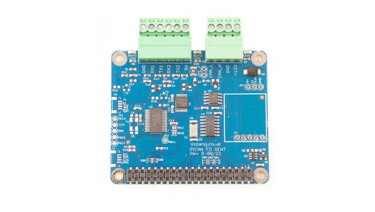
SK Pang RSP-PICANFDSENT PICAN FD and SENT Board for Raspberry Pi
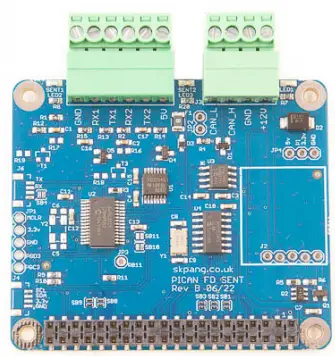
- Product name: PICAN FD and SENT Board for Raspberry Pi
- Model number: RSP-PICANFDSENT
- Manufacturer: SK Pang Electronics Ltd
Introduction
- This PiCAN FD board with SAE J2716 SENT. Classic CAN and CAN FD is provided by the Microchip MCP2518FD IC.
- SAE J2716 SENT is provided by a dsPIC33 micro-controller. Communication to the Pi is over UART on ttyS0 using ASCII text commands. Example SENT GUI app is available written in Python3 and tkinter.
- The firmware is updatable using the Microchip UnifiedHost java app. This requires the Raspberry Pi running in GUI mode.
Easy to install SocketCAN driver. Programming can be done in Python. - Optional 3A SMPS module which can power the PiCAN FD SENT board and Raspberry Pi from 7 to 24v external supply.
CAN Features
- Arbitration Bit Rate upto 1Mbps
- Data Bit Rate up to 8Mbps
- CAN FD Controller modes
- Mixed CAN2.0B and CANFD mode
- Conforms to ISO11898-1:2015
- High speed SPI Interface
- CAN connection via 4way screw terminal
- 120Ω terminator ready
- LED indicator (GPIO04)
- Four fixing holes, comply with Pi Hat standard
- SocketCAN driver, appears as can0 and can1 to application
- Interrupt RX on GPIO25
SAE J2716 SENT Features
- Two independent SAE J2716 SENT channels
- Each channel can be configured for Tx or Rx
- Configurable Tick Time and Frame Time
- Status LED for each channel
- 5v DC output to power small sensor
- Powered by Microchip dsPIC33 micro-controller with updatable firmware
- Communicate to the Pi via ASCII text commands on ttyS0
- Python3 demo GUI app on Raspberry Pi
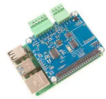
Hardware Installation
Before installing the board make sure the Raspberry Pi is switched off. Carefully align the 40way connector on top of the Pi. Use spacer and screw (optional items) to secure the board.
Screw Terminal Plugs
The CAN connections is made via the 4way screw terminal plug on J3 and SENT on J5.
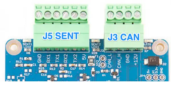
| J5 SENT | Function |
| 1 | GND |
| 2 | RX1 |
| 3 | TX1 |
| 4 | RX2 |
| 5 | TX2 |
| 6 | +5v |
| J3 CAN-Bus | Function |
| 1 | CAN_L |
| 2 | CAN_H |
| 3 | GND |
| 4 | +12v |
CAN-BUS 120W Terminator
There is a 120W fitted to the board. To use the terminator solder a 2way header pin to JP2 then insert a jumper.
LEDs
There is a red LED (LED1) fitted to the board. This is connected to GPIO04. LED2 and LED3 are the SENT status light which is controlled by the dsPIC33.
Optional
SMPS. Switch mode power supply module option, this is a 5v module that can power the board and the Raspberry Pi. It has an input voltage range of 7v to 24v.
Software Installation
It is best to start with a brand new Raspbian image. Download the latest from:
- After first time boot up, do an update and upgrade first.
- sudo apt-get update
- sudo apt-get upgrade
- sudo reboot
- Add these lines to the end of file:
- enable_uart=1
- dtparam=spi=on
- dtoverlay=mcp251xfd,spi0-0,interrupt=25
- Reboot Pi:
sudo reboot
Installing CAN Utils
- Install the CAN utils by:
sudo apt-get install can-utils - Bring Up the Interface
- You can now bring the CAN interface up with CAN 2.0B at 500kbps:
sudo /sbin/ip link set can0 up type can bitrate 500000 - or CAN FD at 500kpbs / 2Mbps. Use copy and paste to a terminal.
sudo /sbin/ip link set can0 up type can bitrate 500000 dbitrate 2000000 fd on sample-point .8 dsample-point .8 - Connect the PiCAN FD LIN board to your CAN network. To send a CAN 2.0 message use :
cansend can0 7DF#0201050000000000 - This will send a CAN ID of 7DF. Data 02 01 05 – coolant temperature request. To send a CAN FD message with BRS use :
cansend can0 7df##15555555555555555 - To send a CAN FD message with no BRS use :
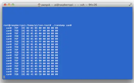
cansend can0 7df##05555555555555555 - Connect the PiCAN to a CAN-bus network and monitor traffic by using command:
cansend can0
- You can now bring the CAN interface up with CAN 2.0B at 500kbps:
- You should see something like this:

Python Installation and Use
- Ensure the driver for PiCAN FD is installed and working correctly first. Clone the pythonCan repository by:
git clone https://github.com/hardbyte/python-can cd python-can sudo python3 setup.py install - Check there is no error been displayed. Bring up the can0 interface:
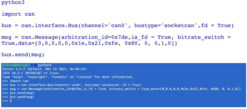
sudo /sbin/ip link set can0 up type can bitrate 500000 dbitrate 2000000 fd on sample-point .8 dsample-point .8 - Now start python3 and try the transmit with CAN FD and BRS set.

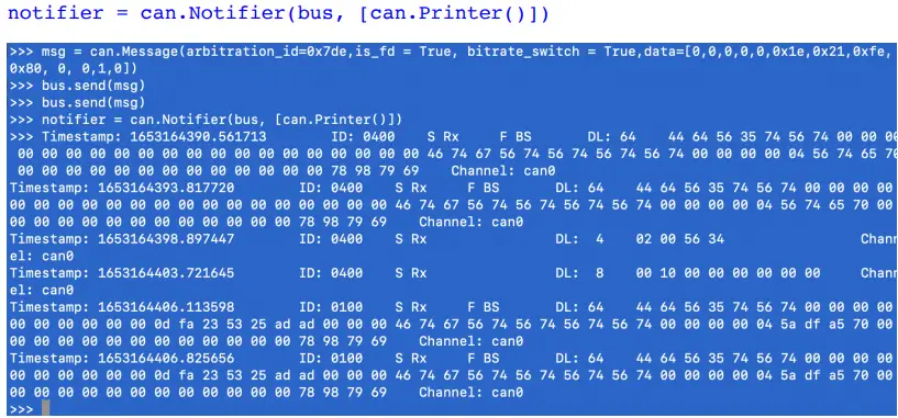
- To received messages and display on screen type in: notifier = can.Notifier(bus, [can.Printer()])

- Documentation for python-can can be found at :
https://python-can.readthedocs.io/en/stable/index.html - More expamles in github:
https://github.com/skpang/PiCAN-FD-Python-examples
SENT Usage
- The SENT controller is communicated to the Pi over the UART on ttyS0 port at 115200 8-N-1 setting.
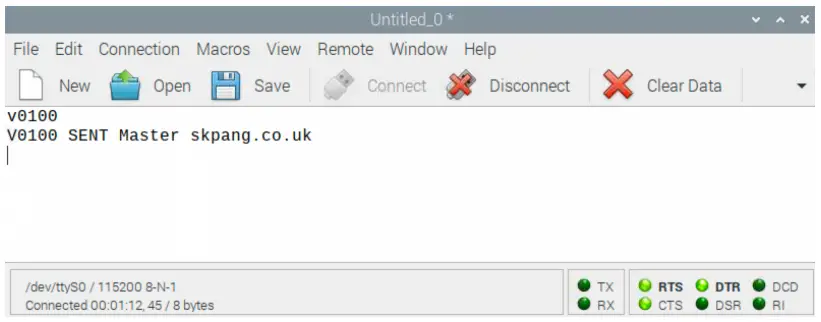
- Using Coolterm for Raspberry Pi or a text base terminal. Set the port to /dev/ttyS0 / 115200 8-N-1 and connect.
- On the terminal type in ‘v’ and press enter. Type in ‘V’ and press enter.
- You should see a reply like this screen:

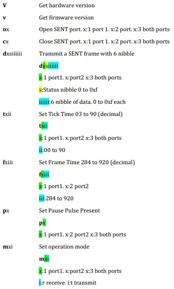
ASCII Command Set
To control the SENT port a simple ASCII command is sent from the Pi to the PICAN FD LIN board.
Commands from Pi to the PiCAN FD SENT board
The command requires a carriage return character (0x0D). All values are in hex.
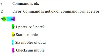
Data from PiCAN FD SENT board to Pi
After each command is received, an acknowledge character is sent back to the Pi
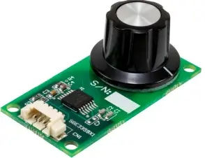
Example 1. Port 1 to receive at 3us tick rate. Device such as Microchip LXE3302AR001 – LX3302A Inductive Position sensor.
To setup port 1 to receive at 3us tick rate.
Command string:
- m1r
- t103
- o1
You should now see a series of data returned like shown below:
- d10E66E66F
- d10E66E66F
- d10E66E66F
- d10E66E66F
- d10E66E66F
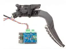
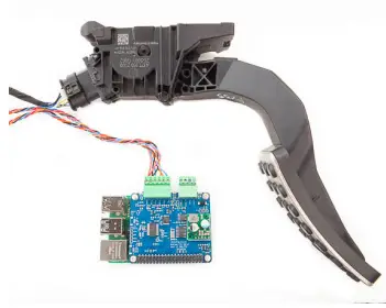
Example 2. To read the output of a vehicle accelerator pedal. This SENT device has two outputs.
To setup port 1 and 2 to receive at 3us tick rate.
Command string:
- m3r
- t103
- t203
- o3
You should now see a series of data returned like shown below
- d140EFFCFE
- d200776CF6
- d140EE15F8
- d2007685F6
SENT GUI Demo
A simple GUI interface is available to download from github:
https://github.com/skpang/PiCAN_SENT_GUI_demo
To run the program start a terminal and type in:
python3 pican-sent.py
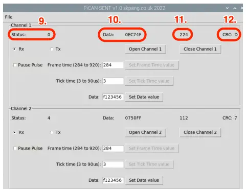
You should see a screen shown below:
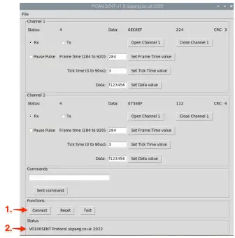
- Click the Connect button to connect to the PiCAN FD SENT board.
- Check the Status box is updated.
Example 1. Connect an accelerator pedal to the board.

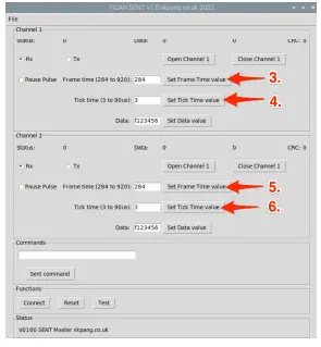
Now click. - Set Frame Time value for Channel 1
- Set Tick Time value for Channel 1
- Set Frame Time value for Channel 2
- Set Tick Time value for Channel 1

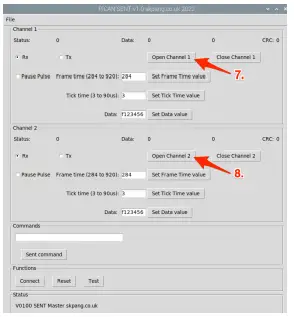
To open the channels click. - Click Open Channel 1
- Click Open Channel 2
You should now see data from both channels.

- Status nibble
- Six data nibble in hex
- First 3 data nibble converted to decimal
- CRC nibble
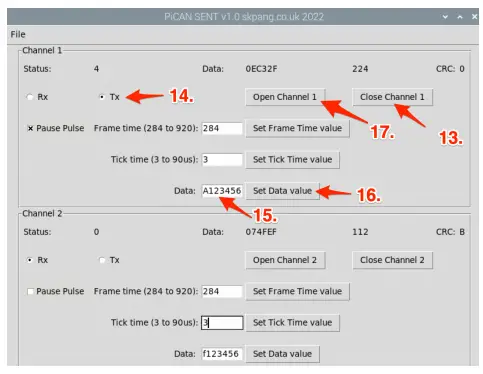
Example 2. Transmitting SENT frames

To transmit SENT frames, click. - Close Channel button
- Tx radio button
- Enter status and data values
- Set Data value button
- Open Channel 1 button
The example data values are
Status nibble : A
Data nibble : 123456
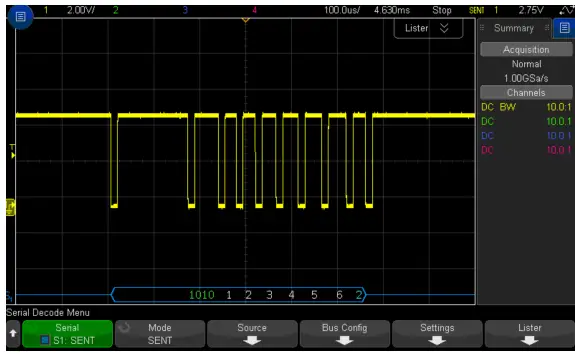
From a scope you should see a waveform like shown below:
This should a status nibble of 0xA. Six data nibble and a CRC of 0x2.
SK Pang Electronics Ltd Ó 2022 www.skpang.co.uk


