![]() Battery monitor
Battery monitor
Installation and user manual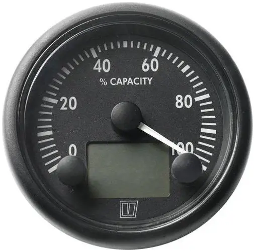 BATMONB
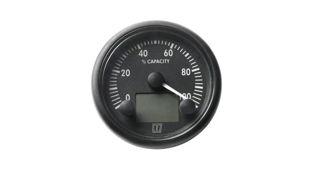
BATMONB Battery Monitor
Introduction
The Vetus battery monitor can be used to measure the charge condition of the battery and also, while discharging, the time remaining before the battery will be completely discharged.
The following functions can be read:
- the charge condition of the battery
- the charge or discharge current
- the voltage
- the time limit before the battery is completely discharged.
A number of alarms can also be set.
The battery monitor can be connected to both a 12 Volt and a 24 Volt system, with negative earthed or earth free (2 pole).
1.1 Explanation used text formatting
‘Text’ : Reference to information on separate sheet.
Text: Text in the display.
Installation
2.1 Meter
- Click the ring onto the meter. Make a hole in the panel and fit the meter.
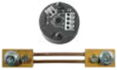
2.2 Shunt, converter and main battery cables
- Install the shunt near the battery or batteries
- Place the converter as close as possible to the shunt and keep the connecting wires between shunt and converter as short as possible.
- Fit a fuse and a main switch in the positive “+” cable.
- Use cable terminals to connect the cables to the shunt, the fuse and the switch. Preferably fit cable terminals by crimping.
- Tighten bolts and nuts securely to ensure a good connection.
– Cable cross-section to be used
| Maximum charge or discharge current | Minimum cross-section battery main cable |
| 70 A | 10 mm2 (AWG 8) |
| 100 A | 16 mm2 (AWG 6) |
| 140 A (135 A) | 25 mm2 (AWG 4) |
| 185 A (180 A) | 35 mm2 (AWG 2) |
| 230 A (210 A) | 50 mm2 (AWG 1) |
![]() Warning!
Warning!
Large currents through too thin wires or contact resistances caused by poor connections can lead to wires or plug connections becoming very hot and could cause a fire.![]() NOTE
NOTE
The shunt resistance supplied is suitable for a maximum current of 200 A. A current larger than 200 A will not be measured correctly.
2.3 Connections
Consult the wiring diagrams, on the separate sheet, how to connect the battery monitor.
For 3 different installations a wiring diagram is supplied:
- Installation with internal combustion engine with 1 battery
- Installation with internal combustion engine with 2 batteries and a battery splitter.
- Installation with electrical propulsion
Consult diagram 4 how to connect a warning buzzer.
Set-up
The instrument must first be set-up before it can be used.
Once it has been set correctly this only has to be done again when the battery or the shunt is replaced.
NOTE
On the separate sheet ‘Operation and Setup’ all the actions to be performed are shown.
- Switch on the power, battery main switch and key switch.
When the power is switched on the pointer on the instrument will indicate the charge condition and on the display the charge or discharge current will be displayed.
3.1 Checking connections shunt to converter
A charging current is shown as positive (no sign before the value of the current).
A discharging current is shown as negative (a “–” sign before the value of the current).
If the polarity of the current is not displayed correctly, then exchange the wires at the converter (3 and 4) which are connected to the shunt.
Use the push button switches to display other information and to carry out the set-up. See ‘Operation and Setup’ on the separate sheet.
3.2 Battery capacity
- Go to Battery Monitor Setup see ‘2 Operation’.
- Press both push buttons simultaneously for at least 3 seconds to select Battery Monitor Setup , see ‘3 Entering battery capacity’. Battery is now selected.
- Press the right push button to enter Battery mode.
- Adjust the value of the battery capacity and press both push buttons simultaneously for at least 3 seconds to confirm.
![]() TIP
TIP
If the battery is in poor condition (old, often been discharged and re-charged, etc.) then enter a lower value then the battery capacity as stated on the battery. A battery of 3 years old can have a capacity of only 80 %.
3.3 Shunt
De supplied shunt is specified for 200 A/100 mV.
If a shunt with a different specification is installed the value for the shunt must be adapted.
- Go to Battery Monitor Setup see ‘2 Operation’.
- Press both push buttons simultaneously for at least 3 seconds to select Battery Monitor Setup, see ‘4 Entering current capacity shunt’.
- Press the left push button once to select Shunt.
- Press the right push button to enter Shunt mode.
- Adjust the value of the shunt and press both push buttons simultaneously for at least 3 seconds to confirm.
| Specification shunt | Value to be set |
| 200 A / 100 mV | 200 A |
| 100 A / 100 mV | 100 A |
| 80 A / 60 mV | 133 A |
| 100 A / 60 mV | 167 A |
| 200 A / 60 mV | 333 A |
3.4 Calibration
- Go to Current, see ‘2 Operation’.
- Short-circuit connections 3 and 4 on the converter.
- Calibrate the instrument if a current is indicated of more than + or – 0.2 A.
- Press both push buttons simultaneously for at least 3 seconds to calibrate the instrument, see ‘5 Calibration current measurement’.
- Remove the short-circuit and re-connect the converter to the shunt.
3.5 Charge condition
Make sure that the battery is fully charged
- Go to Charge, see ‘2 Operation’.
- Press both push buttons simultaneously for at least 3 seconds to set 100 % charge condition, see ‘6 Setting 100 % charge condition’.
3.6 Setting alarms
3 different alarms can be set using the instrument:
– battery charge condition too low: standard setting 20.0%
– battery voltage too low: standard setting 10.0 V
– battery voltage too high: standard setting 30.0 V
- Follow the directions given in ‘1 Summary Operation and Setup’ to set the alarms.
Operating
When the power is switched on the pointer on the instrument will indicate the charge condition and on the display the charge or discharge current will be displayed.
- Press the right push button repeatedly to show the other information in the display, see the separate sheet ‘Operation and Setup’. The pointer will continue to indicate the battery capacity.
4.1 Setting dial illumination
- Go to Dimmer Control, see ‘2 Operation’.
- Dim the brightness by pressing the left push button for at least 3 seconds.
- Increase the brightness by pressing the right push button for at least 3 seconds.
See ‘7 Setting dial illumination’.
4.2 Alarms
In case an alarm condition occurs the warning symbol will be displayed every 30 seconds.
An audible alarm sounds if a buzzer is connected. Press one of the push buttons to switch off the audible alarm. See 3.6 Setting alarms, for setting the alarms.
Trouble shooting
| Problem | Possible cause | Solution |
| The minus sign is displayed together with the charging current instead of the discharge current | Shunt and converter are incorrect connected. | Reverse the connections from the shunt to the converter (3 and 4), see 3.1. |
| Current value is incorrectly displayed. | Calibration of the instrument is required. | Calibrate the instrument, see 3.4. |
| The value entered for the shunt is incorrect. | Enter the correct value, see 3.3. | |
| Charge condition is incorrectly displayed. | The battery capacity entered is incorrect | Enter the correct value, see 3.2. |
| The 100 % charge condi- tion has not been entered with a fully charged battery. | Enter the 100 % charge condition correctly, see 3.5 | |
| An alarm for a too low charge condition. | The charge condition is too low. | Charge the battery. |
| The value entered for the alarm is too high. | Enter a lower value, see 3.6. | |
| An alarm for a too low volt- age. | Voltage is too low. | Charge the battery. |
| The value entered for the alarm is too high. | Enter a lower value, see 3.6. | |
| An alarm for a too high voltage. | Voltage is too high. | Check the alternator voltage regulator and/or the battery charger. |
| The value entered for the alarm is too low. | Enter a higher value, see 3.6. |
Technical data
| Power supply | 12 .. 24 V direct current |
| Power consumption | |
| without dial illumination | 45 mA at 12 V, 30 mA at 24 V |
| dial illumination | 55 mA at 12 V, 35 mA at 24 V |
| Shunt supplied | 200 A / 100 mV |
| Protection | IP66 (only the front of the instrument, after installation) |
| Ambient temperature | 0 .. 50°C |
Display
| Range | Resolution | |
| Voltage | 9 .. 32.6 V | 0.1 V |
| Current | -200 .. +200 A | 0.5 A, for a 200 A / 100 V shunt |
| Battery capacity | 0 .. 100% | 0.1% (digital) |
| Discharge time | 0 .. 999 hour | 0.1 hour |
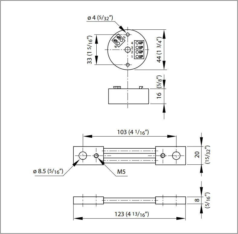
Overall dimensions
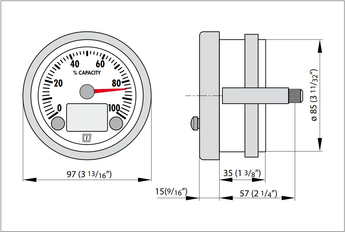 |  |
 | |
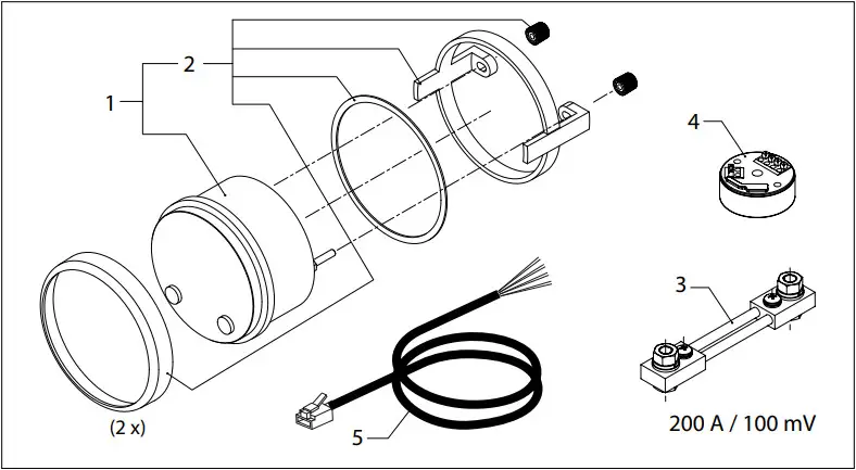
| BATMON | Service onderdelen | Service parts | ||
| pos. | qty | part | be naming | description |
| 1 | 1 | BATM001B | Instrument, zwart | Meter, black |
| 1 | BATM001W | Instrument, wit | Meter, white | |
| 2 | 1 | BATM002 | Montage set | Mounting set |
| 3 | 1 | BATM003 | Shunt | Shunt |
| 4 | 1 | BATM004 | Converter | Converter |
| 5 | 2 | BATM005 | Kabel | Cable |
![]() Fokkerstraat 571 – 3125 BD SCHIEDAM – HOLLAND
Fokkerstraat 571 – 3125 BD SCHIEDAM – HOLLAND
Tel.: +31 (0)88 4884700 – [email protected] – www.vetus.com
Printed in the Netherlands
090433.01 2022-01


