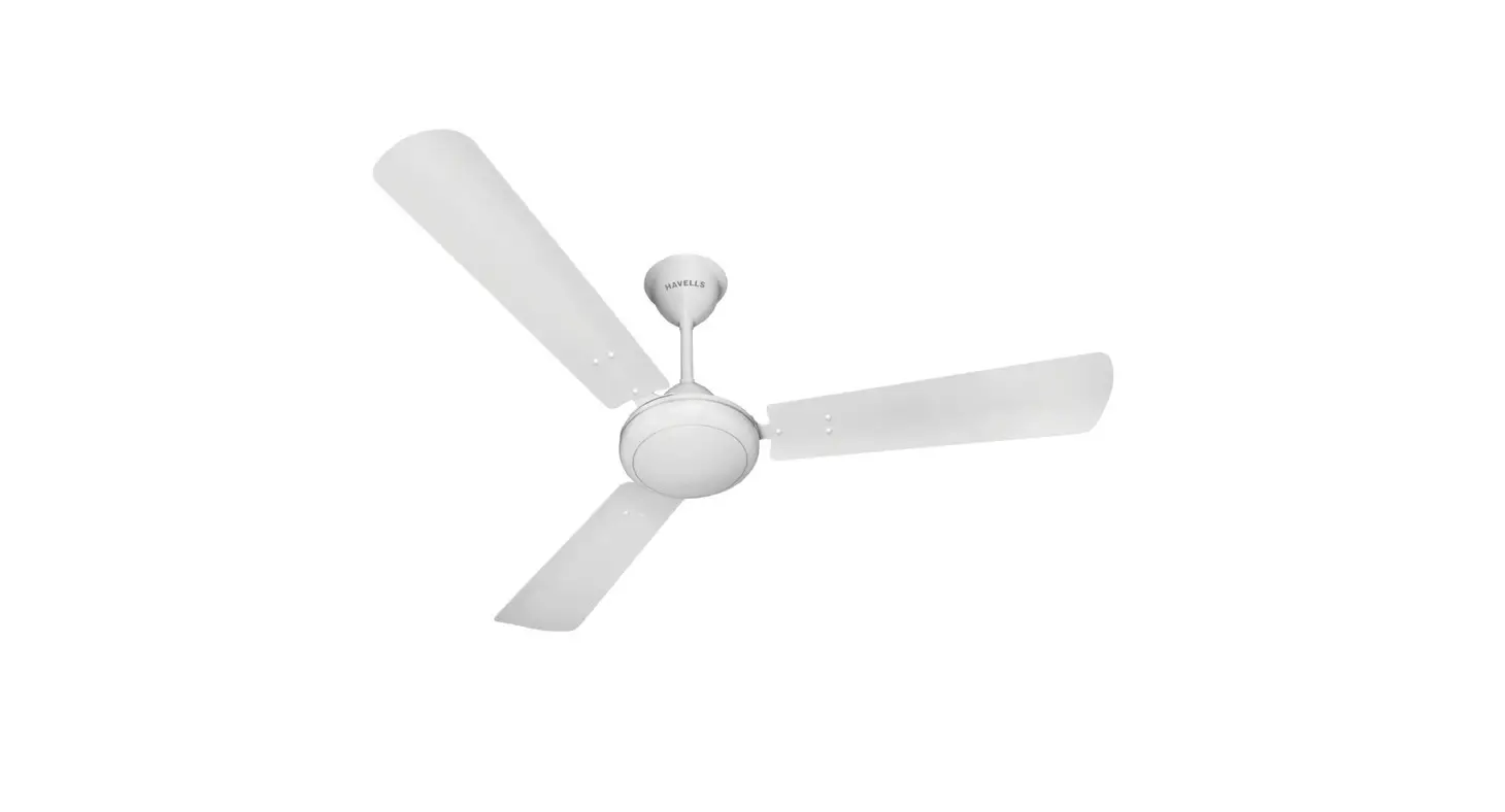
Ceiling Fan H-6555
H-5655 CEILING FAN
1-800-295-5510
uline.com
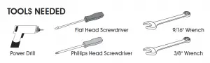
TOOLS NEEDED

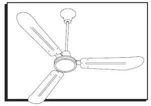
PARTS
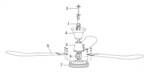
REPLACEMENT PARTS LIST
# | DESCRIPTION |
1 | 18″ Downrod with Rubber Support |
2 | Lower Canopy |
3 | J Hook |
4 | Upper Canopy |
5 | Blade |
6 | Capacitor |
7 | Motor Housing With Yoke |
NOTE: After opening carton, look for concealed damage. If concealed damage is found, immediately file claim with carrier.
SAFETY
![]() WARNING! Disconnect power supply before wiring connections are made to prevent possible electric shock or damage to equipment.
WARNING! Disconnect power supply before wiring connections are made to prevent possible electric shock or damage to equipment.![]() WARNING! Do not operate any fan with a damaged cord or plug. Do not run cord under carpeting. Do not cover cord with throw rugs, runners or similar coverings. Do not route cord under furniture or appliances. Arrange cord away from traffic area and where it will not be tripped over.
WARNING! Do not operate any fan with a damaged cord or plug. Do not run cord under carpeting. Do not cover cord with throw rugs, runners or similar coverings. Do not route cord under furniture or appliances. Arrange cord away from traffic area and where it will not be tripped over.![]() WARNING! Read and follow instructions carefully. Failure to comply with instructions could result in fire, electric shock, injury to persons and/or damage to equipment.
WARNING! Read and follow instructions carefully. Failure to comply with instructions could result in fire, electric shock, injury to persons and/or damage to equipment.![]() WARNING! Do not use an extension cord with this fan.
WARNING! Do not use an extension cord with this fan.
CAUTION! Follow all maintenance procedures enclosed.
![]() DANGER! Failure to properly ground unit could result in severe electrical shock or death.
DANGER! Failure to properly ground unit could result in severe electrical shock or death.
1. All wiring should conform to the National Electrical Code ANSI/NFPA 70-1999 (NEC) in the United States, CEC and local regulations.
2. Do not mount in an area that will allow the ceiling fan to come in contact with moisture.
3. Make certain the entire installation is grounded as a precaution against possible electrical shock.
4. Do not exceed maximum amperage rating of the ceiling fan, as overloading can result in damage to ceiling fan.
5. When wiring an electrical appliance or device, follow all electrical and safety codes, as well as the most recent NEC, CEC and local regulations and the Occupational Safety and Health Act (OSHA).
6. Suitable for use with solid state speed control.
0521 IH-5655
INSTALLATION
This model is manufactured with a cord and a molded three prong electrical plug, which can be installed directly into an electrical outlet.
NOTE: For installation to open web steel joist, use the threaded J hook as supplied. For wood joist construction, use J hook with lag threads (not included). For attachment in concrete, drill concrete anchors into the concrete, as applicable to NEC, CEC and local regulation.
WARNING! To reduce the risk of personal injury, do not bend the blade brackets when installing the brackets, balancing the blades or cleaning the fan. Do not insert foreign objects in between rotating fan blades.
- Prior to installation, ensure all pre-installed set screws, cotter pins and locknuts are tight and secure.
- Slide lower canopy (2) down to the rubber gasket to create a tight seal. Tighten set screw.
- Wind one nut down to bottom of J hook (3) towards the curve. Add a lock washer and then flat washer on top of the nut.
WARNING! Make certain crimps on safety loop are secure (See Figure 1). Make certain safety cable is attached properly to hook or structural member. Failure to comply with instructions could result in personal injury and/or property damage.
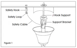
4. Drill a 5/32″ pilot hole for safety hook (See Figure 1) within a 12″ radius of J hook (3) for fan. Wind one nut down to bottom of safety hook towards the loop. Add a lock washer and slide safety hook through pilot hole. Slide lock washer on top side of the safety hook and add nut. Tighten so lock washers on top and bottom of the structure are secure.
J Hook Support Support Bracket
5. Drill a 1/2″ pilot hole for J hook. Put J hook (3) through pilot hole in joist. Add flat washer and then lock washer and nut. Do not tighten completely until fan is put in place on J hook.
NOTE: A lubricant should not be used on the single mounting screw. Pilot hole should be drilled no larger than the minor diameter of the mounting screw threaded. At least 1/” (38mm) of the threaded part of the mounting screw should be secured into a structural joist to provide secure mounting.
IMPORTANT! If a shorter down rod is required, read steps on page 3.
6. Loosen set screw on upper canopy (4) on fan down rod (1) and lower the canopy to make room to place rubber grommet onto mounting J hook.
7. Tighten top nut on J hook to raise fan into proper installation position.
WARNING! When installed properly, the blades will hang 10′ above the floor level. It is critical that the J hook and nut adjustment are done so that the blades will be a minimum 12″ from the ceiling. If your ceiling is less than 12′, then the hook and down rod must be recessed into the ceiling so that the blades are mounted 10′ above the floor level to meet OSHA standards.
8. Raise upper canopy (4) up the down rod to cover hook. Leave 1/8″ gap between upper canopy (4) and hanging surface so down rod does not move off center, which could make fan wobble or vibrate and transmit motor noise to ceiling surface. Tighten set screw on upper canopy (4).
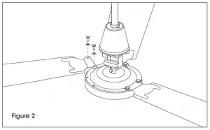
9. Attach blades (5) to motor housing (7) with blade bolts already installed in motor housing. The blade should be positioned below the blade arm bracket when attaching to the motor to get proper air flow and direction. (See Figure 2)
INSTALLATION CONTINUED
CHANGING TO SHORTER DOWNROD:
- Loosen and remove bolt, cotter pin and nut on the fan downrod support bracket. (See Figure 1)
- Slide upper canopy (4) and lower canopy (2) off of the downrod (1) and over the wires and safety cable.
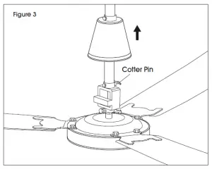
- Loosen set screw and remove cotter pin at the motor and slide the downrod (1) over the wires and safety cable. (See Figure 3)

- Take the shorter downrod and start to reverse steps three to one.
- Slide the shorter downrod over the wire and safety cable and insert into yoke.
- Insert bolt through the yoke and downrod, making certain you do not damage the wires. Once the bolt is in place, re-insert the cotter pin and bend the longer side backwards so it will not slide out.
- Tighten the set screws to 10 foot/lbs. of torque.
- Slide the lower canopy (2) over the wires, safety cable and downrod (1) until it sits on top of the yoke, and tighten the set screw.
- Slide the upper canopy (4) over the wires, safety cable and downrod, and do not tighten the set screw.
- Attach rubber grommet and support bracket to the top of the downrod using bolt, cotter pin and nut. Make certain you do not damage the wires inside the downrod. Tighten the nut to 10 foot/lbs. of torque, re-insert the split pin and bend the longer side backwards so the pin will not slide out.
- Return to the installation instructions.
NOTE: The shorter downrod, when installed properly, is a minimum 10′ above the floor level. It is critical that the J hook and nut adjustment are done so that the blades will be a minimum 12″ from the ceiling. If your ceiling is less than 12′, then the hook and downrod must be recessed into the ceiling so that the blades are mounted 10′ above the floor level to meet OSHA standards.
MAINTENANCE
DANGER! Always disconnect the power supply before servicing the ceiling fan or working with the unit for any reason.
WARNING: Parts replacement and troubleshooting should be performed only by qualified personnel.
WARNING: Do not place fingers or objects in the ceiling fan while motor is connected to the power source.
WARNING: Do not attach foreign objects to the blades of the ceiling fan.
WARNING: Do not use gasoline, benzene, thinner, harsh cleaners, etc., which are dangerous and will damage the ceiling fan.
CAUTION! If you see noticeable vibration, wobbling or wear, the fan should be removed from service and repaired or replaced by a qualified maintenance technician or electrician.
TROUBLESHOOTING
DANGER! Always disconnect the power supply before servicing the ceiling fan or working with the unit for any reason.
WARNING: Parts replacement and troubleshooting should be performed only by qualified personnel.
TROUBLESHOOTING
OPERATING ISSUE Fan will not start. Fan is too fast/slow. Fan makes noise.
Fan wobbles.
OPERATING ISSUE | RECOMMENDATIONS |
Fan will not start. | a) Check fuses and circuit breakers. |
Fan is too fast/slow. | a) Check voltage at fan connection. |
Fan makes noise. | a) Check motor case to make certain all visible screws are snug. |
Fan wobbles. | a) Check that all blade brackets are screwed firmly to motor case. |
PAGE 4 OF 12
1-800-295-5510
uline.com
0521 IH-5655
H-5655 VENTILADOR DE TECHO
800-295-5510
uline.mx


![Hunter Ceiling Fan [59646,51221,51427] Installation Manual](https://static-data1.manualsee.com/1/img/142/40661/2021/01/Hunter-Ceiling-Fan-596465122151427-Installation-Manual.jpg "Hunter Ceiling Fan [59646,51221,51427] Installation Manual")

