
![]() Instruction Manual
Instruction Manual
DCCS623
20V Max* Pruner
www.DEWALT.COM
If you have questions or comments, contact us.
1-800-4-DeWALT
DCCS623 20V Max* Pruner
Components
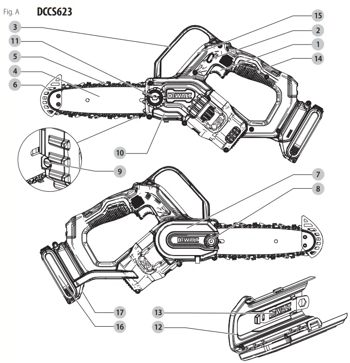
| 1 Trigger switch 2 Lock‑off lever 3 Front hand guard 4 Guide bar 5 Saw chain 6 Bar tip guard 7 Sprocket cover 8 Bar lock nut | 9 Chain tensioning screw 10 Oil level indicator 11 Oil cap 12 Scabbard 13 Wrench 14 Rear handle 15 Front handle 16 Battery Pack 17 Battery release button |
| Fig. B 75–100% charged | Fig. C Indicators/Témoin/Indicador |
| 51–74% charged | Charging Bloc-piles en Cours Bloc-piles en Cours |
< 50% charged |  |
The pack needs to be charged |  Hot/Cold Pack Delay Hot/Cold Pack Delay |
 |  |
 |  |
 |  |
 |  |
 |  |
 |  |
![]() WARNING: Read all safety warnings and all instructions. Failure to follow the warnings and instructions may result in electric shock, fire, and/or serious injury.
WARNING: Read all safety warnings and all instructions. Failure to follow the warnings and instructions may result in electric shock, fire, and/or serious injury.
WARNING: To reduce the risk of injury, read the instruction manual.
Intended Use
The DCCS623 pruner is designed for pruning applications up to 6″ (152 mm) in diameter.
DO NOT use under wet conditions or in presence of flammable liquids or gases.
This pruner is a professional power tool.
DO NOT let children come into contact with the tool. Supervision is required when inexperienced operators use this tool.
Definitions: Safety Alert Symbols and Words
This instruction manual uses the following safety alert symbols and words to alert you to hazardous situations and your risk of personal injury or property damage.![]() DANGER: Indicates an imminently hazardous situation that, if not avoided, will result in death or serious injury.
DANGER: Indicates an imminently hazardous situation that, if not avoided, will result in death or serious injury.![]() WARNING: Indicates a potentially hazardous situation that, if not avoided, could result in death or serious injury.
WARNING: Indicates a potentially hazardous situation that, if not avoided, could result in death or serious injury.![]() CAUTION: Indicates a potentially hazardous situation which, if not avoided, may result in minor or moderate injury. (Used without a word) Indicates a safety-related message.
CAUTION: Indicates a potentially hazardous situation which, if not avoided, may result in minor or moderate injury. (Used without a word) Indicates a safety-related message.![]() NOTICE: Indicates a practice not related to personal injury which, if not avoided, may result in property damage.
NOTICE: Indicates a practice not related to personal injury which, if not avoided, may result in property damage.
GENERAL POWER TOOL SAFETY WARNINGS
WARNING: Read all safety warnings, instructions, illustrations, and specifications provided with this power tool. Failure to follow all instructions listed below may result in electric shock, fire, and/or serious injury.
SAVE ALL WARNINGS AND INSTRUCTIONS FOR FUTURE REFERENCE.
The term “power tool” in the warnings refers to your mains‑operated (corded) power tool or battery‑operated (cordless) power tool.
- Work Area Safety
a ) Keep the work area clean and well-lit. Cluttered or dark areas invite accidents.
b ) Do not operate power tools in explosive atmospheres, such as in the presence of flammable liquids, gases, or dust. Power tools create sparks that may ignite dust or fumes.
c ) Keep children and bystanders away while operating a power tool. Distractions can cause you to lose control. - Electrical Safety
a ) Power tool plugs must match the outlet. Never modify the plug in any way. Do not use any adapter plugs with earthed (grounded) power tools. Unmodified plugs and matching outlets will reduce the risk of electric shock.
b ) Avoid body contact with earthed or grounded surfaces, such as pipes, radiators, ranges, and refrigerators. There is an increased risk of electric shock if your body is earthed or grounded.
c ) Do not expose power tools to rain or wet conditions. Water entering a power tool will increase the risk of electric shock.
d ) Do not abuse the cord. Never use the cord for carrying, pulling, or unplugging the power tool. Keep the cord away from heat, oil, sharp edges, or moving parts. Damaged or entangled cords increase the risk of electric shock.
e ) When operating a power tool outdoors, use an extension cord suitable for outdoor use. The use of a cord suitable for outdoor use reduces the risk of electric shock.
f ) If operating a power tool in a damp location is unavoidable, use a ground fault circuit interrupter (GFCI) protected supply. The use of a GFCI reduces the risk of electric shock. - Personal Safety
a ) Stay alert, watch what you are doing, and use common sense when operating a power tool. Do not use a power tool while you are tired or under the influence of drugs, alcohol, or medication. A moment of inattention while operating power tools may result in serious personal injury.
b ) Use personal protective equipment. Always wear eye protection. Protective equipment such as a dust mask, non‑skid safety shoes, hard hats, or hearing protection used for appropriate conditions will reduce personal injuries.
c ) Prevent unintentional starting. Ensure the switch is in the off‑position before connecting to a power source and/or battery pack, picking up, or carrying the tool. Carrying power tools with your finger on the switch or energizing power tools that have the switch on invites accidents.
d ) Remove any adjusting key or wrench before turning the power tool on. A wrench or a key left attached to a rotating part of the power tool may result in personal injury.
e ) Do not overreach. Keep proper footing and balance at all times. This enables better control of the power tool in unexpected situations.
f ) Dress properly. Do not wear loose clothing or jewelry. Keep your hair, clothing, and gloves away from moving parts. Loose clothes, jewelry, or long hair can be caught in moving parts.
g ) If devices are provided for the connection of dust extraction and collection facilities, ensure these are connected and properly used. The use of dust collection can reduce dust‑related hazards.
h ) Do not let familiarity gained from the frequent use of tools allow you to become complacent and ignore tool safety principles. A careless action can cause severe injury within a fraction of a second. - Power Tool Use and Care
a ) Do not force the power tool. Use the correct power tool for your application. The correct power tool will do the job better and safer at the rate for which it was designed.
b ) Do not use the power tool if the switch does not turn on and off. Any power tool that cannot be controlled with the switch is dangerous and must be repaired.
c ) Disconnect the plug from the power source and/or remove the battery pack, if detachable, from the power tool before making any adjustments, changing accessories, or storing power tools. Such preventive safety measures reduce the risk of starting the power tool accidentally.
d ) Store idle power tools out of the reach of children and do not allow persons unfamiliar with the power tool or these instructions to operate the power tool. Power tools are dangerous in the hands of untrained users.
e ) Maintain power tools and accessories. Check for misalignment or binding of moving parts, breakage of parts, and any other condition that may affect the power tool’s operation. If damaged, have the power tool repaired before use. Many accidents are caused by poorly maintained power tools.
f ) Keep cutting tools sharp and clean. Properly maintained cutting tools with sharp cutting edges are less likely to bind and are easier to control.
g ) Use the power tool, accessories and tool bits, etc. in accordance with these instructions, taking into account the working conditions and the work to be performed. Use of the power tool for operations different from those intended could result in a hazardous situation.
h ) Keep handles and grasping surfaces dry, clean, and free from oil and grease. Slippery handles and grasping surfaces do not allow for safe handling and control of the tool in unexpected situations. - Battery Tool Use and Care
a ) Recharge only with the charger specified by the manufacturer. A charger that is suitable for one type of battery pack may create a risk of fire when used with another battery pack.
b ) Use power tools only with specifically designated battery packs. Use of any other battery packs may create a risk of injury and fire.
c ) When the battery pack is not in use, keep it away from other metal objects, like paper clips, coins, keys, nails, screws, or other small metal objects, that can make a connection from one terminal to another. Shorting the battery terminals together may cause burns or a fire.
d ) Under abusive conditions, liquid may be ejected from the battery; avoid contact. If contact accidentally occurs, flush with water. If liquid contacts the eyes, additionally seek medical help. Liquid ejected from the battery may cause irritation or burns.
e ) Do not use a battery pack or tool that is damaged or modified. Damaged or modified batteries may exhibit unpredictable behavior resulting in fire, explosion, or risk of injury.
f ) Do not expose a battery pack or tool to fire or excessive temperature. Exposure to fire or temperature above 265 °F (130 °C) may cause an explosion.
g ) Follow all charging instructions and do not charge the battery pack or tool outside the temperature range specified in the instructions. Charging improperly or at temperatures outside the specified range may damage the battery and increase the risk of fire. - Service
a ) Have your power tool serviced by a qualified repair person using only identical replacement parts. This will ensure that the safety of the power tool is maintained.
b ) Never service damaged battery packs. Service of battery packs should only be performed by the manufacturer or authorized service providers.
Pruner Safety Warnings
a ) Keep all parts of the body away from the saw chain when the pruner is operating. Before you start the pruner, make sure the saw chain is not contacting anything. A moment of inattention while operating pruners may cause entanglement of your clothing or body with the saw chain.
b ) Always hold the pruner with your right hand on the rear handle and your left hand on the front handle. Holding the pruner with a reversed hand configuration increases the risk of personal injury and should never be done.
c ) Hold the power tool by insulated gripping surfaces only, because the saw chain may contact hidden wiring. Saw chains contacting a “live” wire may make exposed metal parts of the pruner “live” and could give the operator an electric shock.
d ) Wear safety glasses and hearing protection. Further protective equipment for, the head, hands, legs, and feet is recommended. Adequate protective clothing will reduce personal injury from flying debris or accidental contact with the saw chain.
e ) Do not operate a pruner in a tree. Operation of a pruner while up in a tree can result in personal injury.
f ) Always keep proper footing and operate the pruner only when standing on fixed, secure and level surfaces. Slippery or unstable surfaces may cause a loss of balance or control of the pruner.
g ) When cutting a limb that is under tension, be alert for spring back. When the tension in the wood fibers is released, the spring-loaded limb may strike the operator and/or throw the pruner out of control.
h ) Use extreme caution when cutting brush and saplings. The slender material could catch the saw chain and be whipped toward you or pull you off balance.
i ) Carry the pruner by the front handle with the pruner switched off and away from your body.
When transporting or storing the pruner always fit the guide bar scabbard. Proper handling of the pruner will reduce the likelihood of accidental contact with the moving saw chain.
j ) Follow instructions for lubricating, chain tensioning, and changing accessories. An improperly tensioned or lubricated chain could break the pruner chain.
k ) Keep handles dry, clean, and free from oil and grease. Greasy, oily handles are slippery, causing loss of control.
l ) Cut wood only. Do not use pruner for purposes not intended. For example: do not use a pruner for cutting plastic, masonry, or non‑wood building materials. Use of the pruner for operations different than intended could result in a hazardous situation.
m ) Maintain a firm grip, with thumbs and fingers encircling the pruner handles, with both hands on the pruner. Maintaining control of the pruner will reduce the risk of losing control. Do not let go of the pruner.
n ) Do not overreach and do not cut above shoulder height. This enables better control of the pruner in unexpected situations.
o ) Only use replacement bars and chains specified by the manufacturer. Incorrect replacement bars and chains can cause chain breakage and increase the risk of injury.
p ) Follow the manufacturer’s sharpening and maintenance instructions for the pruner chain. Decreasing the depth gauge height can lead to an increased risk of injury.
Causes and Operator Prevention of Kickback:
Kickback may occur when the nose or tip of the guide bar touches an object, or when the wood closes in and pinches the saw chain in the cut.
Tip contact in some cases may cause a sudden reverse reaction, kicking the guide bar up and back toward the operator.
Pinching the saw chain along the top of the guide bar may push the guide bar rapidly back toward the operator.
Either of these reactions may cause you to lose control of the saw which could result in serious personal injury. Do not rely exclusively upon the safety devices built into your saw.
As a pruner user, you should take several steps to keep your cutting jobs free from accidents or injuries.
Kickback is the result of tool misuse and/or incorrect operating procedures or conditions and can be avoided by taking proper precautions as given below:
a ) Maintain a firm grip, with thumbs and fingers encircling the pruner handles, with both hands on the saw, and position your body and arm to allow you to resist kickback forces. Kickback forces can be controlled by the operator, if proper precautions are taken. Do not let go of the pruner.
b ) Do not overreach and do not cut above shoulder height. This helps prevent unintended tip contact and enables better control of the pruner in unexpected situations.
c ) Only use replacement bars and chains specified by the manufacturer. Incorrect replacement bars and chains may cause chain breakage and/or kickback.
d ) Follow the manufacturer’s sharpening and maintenance instructions for the saw chain.
Decreasing the depth gauge height can lead to increased kickback.
The Following Precautions Should Be Followed to Minimize Kickback:
- Grip saw firmly. Hold the pruner firmly with both hands when the motor is running. Use a firm grip with thumbs and fingers encircling the pruner handles. Pruner will pull forward when cutting on the bottom edge of the bar, and push backward when cutting along the top edge of the bar.
- Do not overreach.
- Keep proper footing and balance at all times.
- Don’t let the nose of the guide bar contact a log, branch, ground, or other obstruction.
- Don’t cut above shoulder height.
- Use devices such as low kickback chains and reduced kickback guide bars that reduce the risks associated with kickbacks.
- Only use replacement bars and chains specified by the manufacturer or the equivalent.
- Never let the moving chain contact any object at the tip of the guide bar.
- Keep the working area free from obstructions such as other trees, branches, rocks, fences, stumps, etc. Eliminate or avoid any obstruction that your saw chain could hit while you are cutting through a particular log or branch.
- Keep your saw chain sharp and properly tensioned. A loose or dull chain can increase the chance of kickback. Check tension at regular intervals with the motor stopped and the tool unplugged, never with the motor running.
- Begin and continue cutting only with the chain moving at full speed. If the chain is moving at a slower speed, there is a greater chance for a kickback to occur.
- Cut one log at a time.
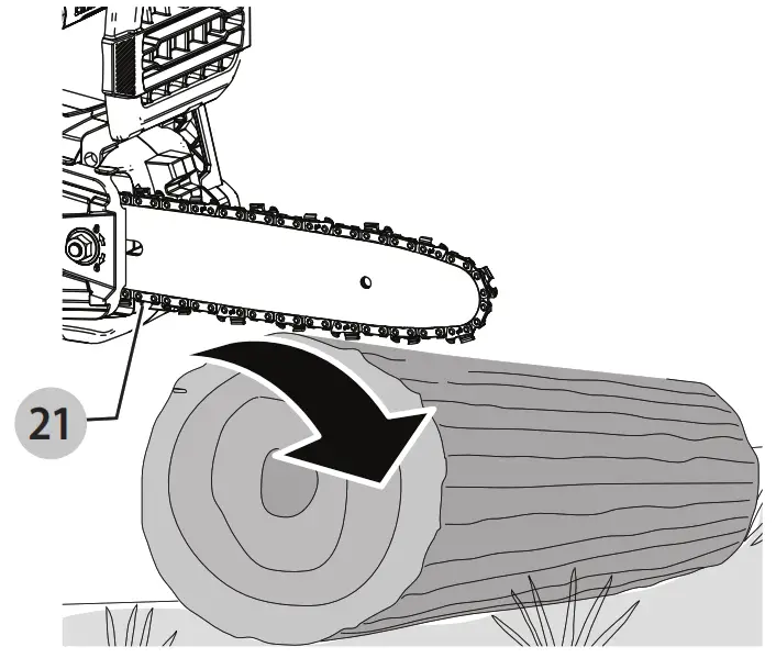
- Use extreme caution when re‑entering a previous cut. Engage the ribbed bumpers 21 onto the wood and allow the chain to reach full speed before proceeding with a cut.
- Do not attempt plunge cuts or bore cuts.
- Watch for shifting logs or other forces that could close a cut and pinch or fall into the chain.
Kickback Safety Features![]() WARNING: The following features are included on your saw to help reduce the hazard of kickback; however such features will not totally eliminate this dangerous reaction. As a pruner user do not rely only on safety devices. You must follow all safety precautions, instructions, and maintenance in this manual to help avoid kickbacks and other forces which can result in serious injury.
WARNING: The following features are included on your saw to help reduce the hazard of kickback; however such features will not totally eliminate this dangerous reaction. As a pruner user do not rely only on safety devices. You must follow all safety precautions, instructions, and maintenance in this manual to help avoid kickbacks and other forces which can result in serious injury.
- Reduced‑Kickback Guide Bar, designed with a small radius tip which reduces the size of the kickback danger zone on the bar tip. A reduced ‑ kickback guide bar is one that has been demonstrated to significantly reduce the number and seriousness of kickbacks when tested in accordance with safety requirements for electric pruners.
- Low‑Kickback Chain, designed with a contoured depth gauge and guard link which deflects kickback force and allows the wood to gradually ride into the cutter. A low‑kickback chain is a chain that has met the kickback performance requirements of ANSI B175.1–2012.
- Do not operate the pruner while in a tree, on a ladder, on a scaffold, or on an unstable surface.
- Hold the tool by insulating gripping surfaces when performing an operation where the cutting tool may contact hidden wiring. Contact with a “live” wire will make exposed metal parts of the tool “live” and shock the operator.
- Do not attempt operations beyond your capacity or experience. Read thoroughly and understand completely all instructions in this manual.
- Before you start the pruner, make sure the saw chain is not contacting any object.
- Do not operate a pruner with one hand! Serious injury to the operator, helpers, or bystanders may result from a one-handed operation. A pruner is intended for two‑handed Use only.
- Keep the handles dry, clean, and free of oil or grease.
- Do not allow dirt, debris, or sawdust to build up on the motor or outside air vents.
- Stop the pruner before setting it down.
- Do not cut vines and/or small underbrush.
- Use extreme caution when cutting small-size brushes and saplings because slender material may catch the saw chain and be whipped toward you or pull you off balance.
Pruner Names and Terms
- Bucking ‑ The process of cross-cutting a felled tree or log into lengths.
- Motor Brake (if equipped) ‑ A device used to stop the saw chain when the trigger is released.
- Pruner Powerhead ‑ A pruner without the saw chain and guide bar.
- Bucking ‑ The process of cross-cutting a felled tree or log into lengths.
- Motor Brake (if equipped) ‑ A device used to stop the saw chain when the trigger is released.
- Pruner Powerhead ‑ A pruner without the saw chain and guide bar. guides the saw chain.
- Scabbard/Guide Bar Cover ‑ Enclosure fitted over guide bar to help prevent tooth contact when the saw is not in use.
- Kickback ‑ The backward or upward motion, or both of the guide bar occurring when the saw chain near the nose of the top area of the guide bar contacts any object such s a log or branch, or when the wood closes in and pinches the saw chain in the cut.
- Kickback, Pinch ‑ The rapid pushback of the saw which can occur when the wood closes in and pinches the moving saw chain in the cut along the top of the guide bar.
- Kickback, Rotational ‑ The rapid upward and backward motion of the saw which can occur when the moving saw chain near the upper portion of the tip of the guide bar contacts an object, such as a log or branch.
- Limbing ‑ Removing the branches from a fallen tree.
- Low‑Kickback Chain ‑ A chain that complies with the kickback performance requirements of ANSI B175.1–2012 (when tested on a representative sample of pruners.)
- Normal Cutting Position ‑ Those positions assumed in performing the bucking and felling cuts.
- Notching Undercut ‑ A notch cut in a tree that directs the tree’s fall.
- Rear Handle ‑ The support handle is located at or toward the rear of the saw.
- Reduced Kickback Guide Bar ‑ A guide bar that has been demonstrated to reduce kickback significantly.
- Replacement Saw Chain ‑ A chain that complies with kickback performance requirements of ANSI B175.1–2012 when tested with specific pruners. It may not meet the ANSI performance requirements when used with other saws.
- Saw Chain ‑ A loop of the chain having cutting teeth, that cut the wood, and that is driven by the motor and is supported by the guide bar.
- Ribbed Bumper ‑ The ribs used when felling or bucking to pivot the saw and maintain position while sawing.
- Switch ‑ A device that when operated will complete or interrupt an electrical power circuit to the motor of the pruner.
- Switch Linkage ‑ The mechanism that transmits motion from a trigger to the switch.
- Switch Lockout ‑ A movable stop that prevents the unintentional operation of the switch until manually actuated.
Additional Safety Information
![]() WARNING: Never modify the power tool or any part of it. Damage or personal injury could result.
WARNING: Never modify the power tool or any part of it. Damage or personal injury could result.![]() WARNING: ALWAYS use safety glasses. Everyday eyeglasses are NOT safety glasses. Also, use a face or dust mask if the operation is dusty. ALWAYS WEAR CERTIFIED SAFETY EQUIPMENT:
WARNING: ALWAYS use safety glasses. Everyday eyeglasses are NOT safety glasses. Also, use a face or dust mask if the operation is dusty. ALWAYS WEAR CERTIFIED SAFETY EQUIPMENT:
- ANSI Z87.1 eye protection (CAN/CSA Z94.3),
- ANSI S12.6 (S3.19) hearing protection,
- NIOSH/OSHA/MSHA respiratory protection.
![]() WARNING: Some dust contains chemicals known to the State of California to cause cancer, birth defects, or other reproductive harm. Some examples of these chemicals are:
WARNING: Some dust contains chemicals known to the State of California to cause cancer, birth defects, or other reproductive harm. Some examples of these chemicals are:
- compounds in fertilizers,
- compounds in insecticides, herbicides, and pesticides,
- arsenic and chromium from chemically treated lumber.
To reduce your exposure to these chemicals, wear approved safety equipment such as dust masks that are specially designed to filter out microscopic particles.
- Avoid prolonged contact with dust from power sanding, sawing, grinding, drilling, and other construction activities. Wear protective clothing and wash exposed areas with soap and water. Allowing dust to get into your mouth and eyes, or lay on the skin may promote the absorption of harmful chemicals.
![]() WARNING: Use of this tool can generate and/or disperse dust, which may cause serious and permanent respiratory or another injury. Always use NIOSH/OSHA-approved respiratory protection appropriate for dust exposure. Direct particles away from the face and body.
WARNING: Use of this tool can generate and/or disperse dust, which may cause serious and permanent respiratory or another injury. Always use NIOSH/OSHA-approved respiratory protection appropriate for dust exposure. Direct particles away from the face and body.![]() WARNING: Always wear proper personal hearing protection that conforms to ANSI S12.6 (S3.19) during use. Under some conditions and duration of use, noise from this product may contribute to hearing loss.
WARNING: Always wear proper personal hearing protection that conforms to ANSI S12.6 (S3.19) during use. Under some conditions and duration of use, noise from this product may contribute to hearing loss.![]() CAUTION: When not in use, place the tool on its side on a stable surface where it will not cause a tripping or falling hazard. Some tools with a large battery pack will stand upright but may be easily knocked over.
CAUTION: When not in use, place the tool on its side on a stable surface where it will not cause a tripping or falling hazard. Some tools with a large battery pack will stand upright but may be easily knocked over.
- Air vents often cover moving parts and should be avoided.
Loose clothes, jewelry, or long hair can be caught in moving parts.
The label on your tool may include the following symbols. The symbols and their definitions are as follows:
V ……………………. volts
Hz ………………….. hertz
min ………………… minutes![]() or DC …… direct current
or DC …… direct current![]() …………………. Class I Construction (grounded)
…………………. Class I Construction (grounded)
…/min ………….. per minute
BPM ……………….. beats per minute
IPM ………………… impacts per minute
RPM ……………….. revolutions per minute
sfpm ………………. surface feet per minute
SPM ……………….. strokes per minute
A ……………………. amperes
W …………………… watts![]() or AC ……….. alternating current
or AC ……….. alternating current![]() or AC/DC …. alternating or direct current
or AC/DC …. alternating or direct current
![]() …………………. Class II Construction (double insulated)
…………………. Class II Construction (double insulated)
no ………………….. no load speed
n ……………………. rated speed
m/s ………………… meters per second![]() …………………. earthing terminal
…………………. earthing terminal![]() …………. safety alert symbol
…………. safety alert symbol![]() …………. Visible radiation
…………. Visible radiation![]() …………. Wear respiratory protection
…………. Wear respiratory protection![]() …………. Wear eye protection
…………. Wear eye protection![]() …………. Wear hearing protection
…………. Wear hearing protection![]() …………. Read all documentation
…………. Read all documentation
CSPM ………. Cut strokes per minute![]() …………. Do not leave in the rain
…………. Do not leave in the rain![]() …………. Do not use the front hand guard as a handle
…………. Do not use the front hand guard as a handle![]() ………… Tip contact can cause the guide bar to move suddenly upward and backward, which can cause serious injury
………… Tip contact can cause the guide bar to move suddenly upward and backward, which can cause serious injury![]() ………… Contact of the guide bar tip with any object should be avoided
………… Contact of the guide bar tip with any object should be avoided![]() ……….. The rotational direction of the saw chain
……….. The rotational direction of the saw chain …… Always use two hands when operating the pruner
BATTERIES AND CHARGERS
The battery pack is not fully charged out of the carton.
Before using the battery pack and charger, read the safety instructions below and then follow the charging procedures outlined. When ordering replacement battery packs, be sure to include the catalog number and voltage.
READ ALL INSTRUCTIONS
Important Safety Instructions for All Battery Packs![]() WARNING: Read all safety warnings, instructions, and cautionary markings for the battery pack, charger, and product. Failure to follow the warnings and instructions may result in electric shock, fire, and/or serious injury.
WARNING: Read all safety warnings, instructions, and cautionary markings for the battery pack, charger, and product. Failure to follow the warnings and instructions may result in electric shock, fire, and/or serious injury.
- Do not charge or use the battery pack in explosive atmospheres, such as in the presence of flammable liquids, gases, or dust. Inserting or removing the battery pack from the charger may ignite dust or fumes.
- NEVER force the battery pack into the charger. DO NOT modify the battery pack in any way to fit into a non‑compatible charger as the battery pack may rupture causing serious personal injury. Consult the chart at the end of this manual for the compatibility of batteries and chargers.
- Charge the battery packs only in DeWALT chargers.
- DO NOT splash or immerse in water or other liquids.
- DO NOT allow water or any liquid to enter the battery pack.
- Do not store or use the tool and battery pack in locations where the temperature may reach or exceed 104 °F (40 °C) (such as outside sheds or metal buildings in summer). For the best life store battery packs in a cool, dry location.
NOTE: Do not store the battery packs in a tool with the trigger switch locked on. Never tape the trigger switch in the ON position. - Do not incinerate the battery pack even if it is severely damaged or completely worn out. The battery pack can explode in a fire. Toxic fumes and materials are created when lithium‑ion battery packs are burned.
- Do not expose a battery pack or appliance to fire or excessive temperature. Exposure to fire or temperature above 265 °F (130 °C) may cause an explosion.
- Follow all charging instructions and do not charge the battery pack or appliance outside of the temperature range specified in the instructions. Charging improperly or at temperatures outside of the specified range may damage the battery and increase the risk of fire.
- If battery contents come into contact with the skin, immediately wash the area with mild soap and water. If battery liquid gets into the eye, rinse water over the open eye for 15 minutes or until irritation ceases. If medical attention is needed, the battery electrolyte is composed of a mixture of liquid organic carbonates and lithium salts.
- Contents of opened battery cells may cause respiratory irritation. Provide fresh air. If symptoms persist, seek medical attention.
- Battery liquid may be flammable if exposed to a spark or flame.
- Never attempt to open the battery pack for any reason. If the battery pack case is cracked or damaged, do not insert it into the charger. Do not crush, drop or damage the battery pack. Do not use a battery pack or charger that has received a sharp blow, been dropped, run over, or damaged in any way (e.g., pierced with a nail, hit with a hammer, stepped on). Damaged battery packs should be returned to the service center for recycling.
Storage Recommendations
The best storage place is one that is cool and dry, away from direct sunlight and excess heat or cold. Store the fully charged battery pack out of the charger.
Battery Pack Cleaning Instructions
Dirt and grease may be removed from the exterior of the battery pack using a cloth or soft non‑metallic brush. Do not use water or any cleaning solutions.
Fuel Gauge Battery Packs (Fig. B)
Some battery packs include a fuel gauge. When the fuel gauge button is pressed and held, the LED lights will indicate the approximate level of charge remaining. This does not indicate tool functionality and is subject to variation based on product components, temperature, and end‑user application.
Transportation
![]() WARNING: Fire hazard. Do not store, carry, or transport the battery pack so that metal objects can contact exposed battery terminals. For example, do not place the battery pack in aprons, pockets, tool boxes, product kit boxes, drawers, etc., with loose nails, screws, keys, coins, hand tools, etc. When transporting individual battery packs, make sure that the battery terminals are protected and well insulated from materials that could contact them and cause a short circuit. NOTE: Li‑ion battery packs should not be put in checked baggage on airplanes and must be properly protected from short circuits if they are in carry‑on baggage.
WARNING: Fire hazard. Do not store, carry, or transport the battery pack so that metal objects can contact exposed battery terminals. For example, do not place the battery pack in aprons, pockets, tool boxes, product kit boxes, drawers, etc., with loose nails, screws, keys, coins, hand tools, etc. When transporting individual battery packs, make sure that the battery terminals are protected and well insulated from materials that could contact them and cause a short circuit. NOTE: Li‑ion battery packs should not be put in checked baggage on airplanes and must be properly protected from short circuits if they are in carry‑on baggage.
shipping the DeWALT FlEXVOlT® Battery Pack
The DeWALT FLEXVOLT® battery pack has a battery cap that should be used when shipping the battery pack.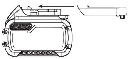
Attach the cap to the battery pack to ready it for shipping. This converts the battery pack to three separate 20V batteries. The three batteries have the Watt-hour rating labeled “Shipping” on the battery pack. If shipping without the cap or in a tool, the pack is one battery at the Watt-hour rating labeled “Use”.
Example battery pack label:
USE: 120 Wh SHIPPING: 3 x 40 Wh
In this example, the battery pack is three batteries with 40 Watt hours each when using the cap. Otherwise, the battery pack is one battery with 120 Watt-hours.
The RBRC® Seal
Please take your spent battery packs to an authorized DeWALT service center or to your local retailer for recycling. In some areas, it is illegal to place spent battery packs in the trash. You may also contact your local recycling center for information on where to drop off the spent battery pack. Do not place in curbside recycling. For more information visit www.call2recycle.org. or call the toll-free number in the RBRC® Seal. 
RBRC® is a registered trademark of Call 2 Recycle, Inc.
Important Safety Instructions for All Battery Chargers
![]() WARNING: Read all safety warnings, instructions, and cautionary markings for the battery pack, charger, and product. Failure to follow the warnings and instructions may result in electric shock, fire, and/or serious injury.
WARNING: Read all safety warnings, instructions, and cautionary markings for the battery pack, charger, and product. Failure to follow the warnings and instructions may result in electric shock, fire, and/or serious injury.
- DO NOT attempt to charge the battery pack with any chargers other than a DeWALT charger. DeWALT chargers and battery packs are specifically designed to work together.
- These chargers are not intended for any use other than charging DeWALT rechargeable battery packs. Charging other types of battery packs may cause them to overheat and burst, resulting in personal injury, property damage, fire, electric shock, or electrocution.
- Do not expose the charger to rain or snow.
- Do not allow water or any liquid to enter the charger.
- Pull by the plug rather than the cord when disconnecting the charger. This will reduce the risk of damage to the electric plug and cord.
- Make sure that the cord is located so that it will not be stepped on, tripped over, or otherwise subjected to damage or stress.
- Do not use an extension cord unless it is absolutely necessary. The use of improper extension cords could result in a risk of fire, electric shock, or electrocution.
- When operating a charger outdoors, always provide a dry location and use an extension cord suitable for outdoor use. The use of a cord suitable for outdoor use reduces the risk of electric shock.
- An extension cord must have an adequate wire size (AWG or American Wire Gauge) for safety. The smaller the gauge number of the wire, the heavier the cord and thus the greater it’s capacity. An undersized cord will cause a drop in line voltage resulting in loss of power and overheating. The following table shows the correct size to use depending on the total length of all extension cords plugged together, and the nameplate ampere rating. If in doubt, use the next heavier gauge.
Minimum gauge for Cord sets
| Volts | Total Length of Cord in Feet (meters) | ||||
| 120V | 25 (7.6) | 50 (15.2) | 100 (30.5) | 150 (45.7) | |
| Ampere Rating | American Wire Gauge | ||||
| More Than | Not More Than | ||||
| 0 | 6 | 18 | 16 | 16 | 14 |
| 6 | 10 | 18 | 16 | 14 | 12 |
| 10 | 12 | 16 | 16 | 14 | 12 |
| 12 | 16 | 14 | 12 | Not Recommended | |
- Do not place any object on top of the charger or place the charger on a soft surface that might block the ventilation slots and result in excessive internal heat. Place the charger in a position away from any heat source. The charger is ventilated through slots in the top and the bottom of the housing.
- Do not operate the charger with a damaged cord or plug. Have them replaced immediately.
- Do not operate the charger if it has received a sharp blow, been dropped, or otherwise damaged in any way. Take it to an authorized service center.
- Do not disassemble the charger; take it to an authorized service center when service or repair is required. Incorrect reassembly may result in a risk of electric shock, electrocution, or fire.
- The charger is designed to operate on standard 120V household electrical power. Do not attempt to use it on any other voltage. This does not apply to the vehicular charger.
- Foreign materials of a conductive nature, such as but not limited to, grinding dust, metal chips, steel wool, aluminum foil, or any buildup of metallic particles should be kept away from the charger cavities and ventilation slots.
- Always unplug the charger from the power supply when there is no battery pack in the cavity.
Charging a Battery (Fig. C)
- Plug the charger into an appropriate outlet.
- Insert and fully seat battery pack 16. The red charging light(s) will continuously blink while charging.
- Charging is complete when the red charging light(s) remain(s) continuously ON. The battery pack can be left in the charger or removed. Some chargers require the battery pack release button to be pressed for removal.
 WARNING: Only charge batteries in air temperatures over 40 ° F (4.5 ° C) and below 104 ° F (+40 ° C).
 - The charger will not charge a faulty battery pack, which may be indicated by the charging light(s) staying OFF. Take the charger and battery pack to an authorized service center if the light(s) stay(s) OFF.
Note: Refer to the label near the charging light(s) on the charger for blink patterns. Older chargers may have additional information and/or may not have a yellow indicator light.
Note: To remove the battery pack, some chargers require the battery pack release button to be pressed.
Hot/Cold Pack Delay
When the charger detects a battery pack that is too hot or too cold, it automatically starts a Hot/Cold Pack Delay, suspending charging until the battery pack has reached an appropriate temperature. The charger then automatically switches to the pack charging mode. This feature ensures maximum battery pack life.
A cold battery pack may charge at a slower rate than a warm battery pack.
The hot/cold pack delay will be indicated by the red light(s) continuing to blink but with the yellow light continuously ON. Once the battery pack has reached an appropriate temperature, the yellow light will turn OFF and the charger will resume the charging procedure.
DCB118 and DCB1112 Chargers
The DCB118 and DCB1112 chargers are equipped with an internal fan designed to cool the battery pack. The fan will turn on automatically when the battery pack needs to
be cooled.
Never operate the charger if the fan does not operate properly or if ventilation slots are blocked. Do not permit foreign objects to enter the interior of the charger.
Electronic Protection System
Li‑Ion tools are designed with an Electronic Protection system that will protect the battery pack against overloading, overheating or deep discharge. The tool will automatically turn off and the battery pack will need to be recharged.
Important Charging Notes
- The longest life and best performance can be obtained if the battery pack is charged when the air temperature is between 65 °F – 75 °F (18 ° C– 24 °C). DO NOT charge when the battery pack is below +40 °F (+4.5 °C), or above +104 °F (+40 °C). This is important and will prevent serious damage to the battery pack.
- The charger and battery pack may become warm to the touch while charging. This is a normal condition and does not indicate a problem. To facilitate the cooling of the battery pack after use, avoid placing the charger or battery pack in a warm environment such as in a metal shed or an uninsulated trailer.
- If the battery pack does not charge properly:
a. Check the operation of the receptacle by plugging in a lamp or other appliance;
b. Check to see if the receptacle is connected to a light switch which turns the power off when you turn out the lights;
c. If charging problems persist, take the tool, battery pack, and charger to your local service center. - You may charge a partially used pack whenever you desire with no adverse effect on the battery pack.
Charger Cleaning Instructions
![]() WARNING: Shock hazard. Disconnect the charger from the AC outlet before cleaning. Dirt and grease may be removed from the exterior of the charger using a cloth or soft non‑metallic brush. Do not use water or any cleaning solutions.
WARNING: Shock hazard. Disconnect the charger from the AC outlet before cleaning. Dirt and grease may be removed from the exterior of the charger using a cloth or soft non‑metallic brush. Do not use water or any cleaning solutions.
Wall Mounting
Some DEWALT chargers are designed to be wall mountable or to sit upright on a table or work surface. If wall mounting, locate the charger within reach of an electrical outlet, and away from a corner or other obstructions which may impede airflow. Use the back of the charger as a template for the location of the mounting screws on the wall. Mount the charger securely using drywall screws (purchased separately) at least 1” (25.4 mm) long, with a screw head diameter of 0.28–0.35” (7–9 mm), screwed into wood to an optimal depth leaving approximately 7/32” (5.5 mm) of the screw exposed. Align the slots on the back of the charger with the exposed screws and fully engage them in the slots.
SAVE THESE INSTRUCTIONS FOR FUTURE USE
ASSEMBLY AND ADJUSTMENTS![]() WARNING: To reduce the risk of serious personal injury, turn the unit off and remove the battery pack before making any adjustments or removing/ installing attachments or accessories. An accidental start‑up can cause injury.
WARNING: To reduce the risk of serious personal injury, turn the unit off and remove the battery pack before making any adjustments or removing/ installing attachments or accessories. An accidental start‑up can cause injury.
Installing the Guide Bar and Saw Chain (Fig. A, D–H)![]() CAUTION: Sharp chain. Always wear protective gloves when handling the chain. The chain is sharp and can cut you when it is not running.
CAUTION: Sharp chain. Always wear protective gloves when handling the chain. The chain is sharp and can cut you when it is not running.![]() WARNING: Sharp moving chain. To prevent accidental operation, ensure that battery is removed from the tool before performing the following operations. Failure to do this could result in serious personal injury. If saw chain 5 and guide bar 4 are packed separately in the carton, the chain has to be attached to the bar, and both must be attached to the body of the tool.
WARNING: Sharp moving chain. To prevent accidental operation, ensure that battery is removed from the tool before performing the following operations. Failure to do this could result in serious personal injury. If saw chain 5 and guide bar 4 are packed separately in the carton, the chain has to be attached to the bar, and both must be attached to the body of the tool.
- Place the saw on a flat, firm surface.
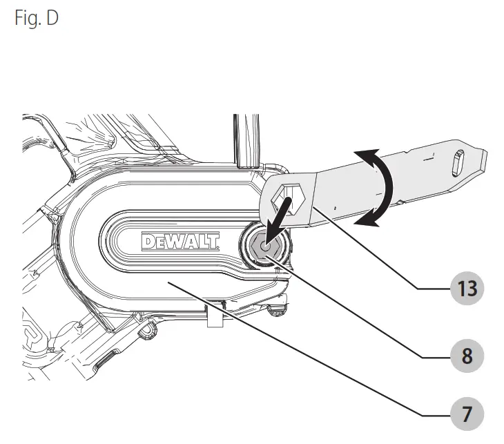
- Rotate the bar lock nut 8 counterclockwise with the wrench 13 provided.
- Remove sprocket cover 7, and bar lock nut 8.
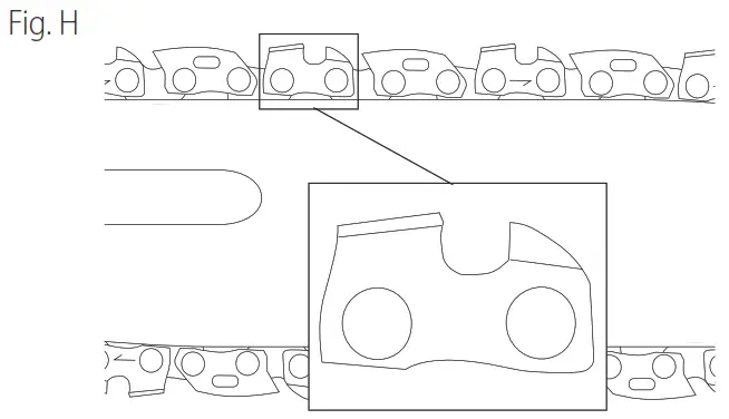
- Wearing protective gloves, grasp the saw chain 5 and wrap it around guide bar 4, ensuring the teeth are facing the correct direction (Fig. H).
- Ensure the chain is properly set in the slot around the entire guide bar.
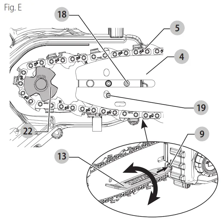
- Place the saw chain around the sprocket 22. While lining up the slot on the guide bar with chain tensioning pin 19, and bolt 18, on the base of the tool as shown in Fig. E.
- Once in place, hold the bar still, and replace the sprocket cover 7. Install the rear of the sprocket cover first, rotate it down, and make sure the bolt hole on the cover lines up with bolt 18, on the main housing.
- Install the bar lock nut 8 and rotate clockwise with the wrench 13 provided until snug, then loosen the nut one full turn, so that the saw chain can be properly tensioned.
- Rotate the chain tensioning screw 9 clockwise to increase tension as shown in Fig. E. Make sure the saw chain 5 is snug around the guide bar 4 . Tighten the bar lock nut 8 until snug.
- Follow the instructions in the section Adjusting Chain Tension.
Adjusting Chain Tension (Fig. A, D–G)
NOTE: Saw chain tension should be adjusted regularly before each use.
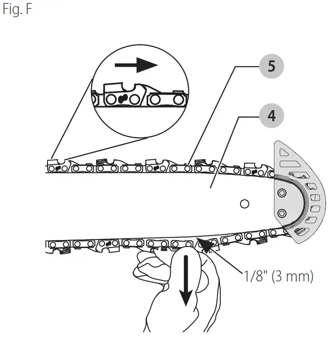
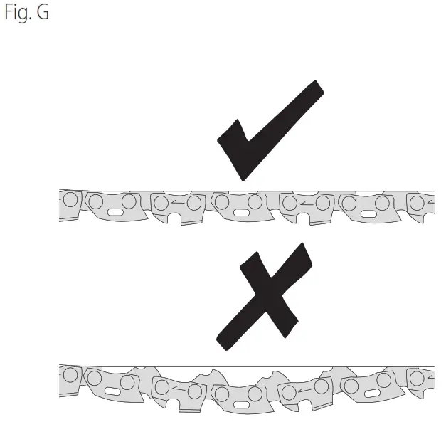
- With the saw still on a firm surface check the saw chain 5 tension. The tension is correct when the saw chain snaps back after being pulled 1/8″ (3 mm) away from the guide bar 4 with light force from the middle finger and thumb as shown in Fig. F. There should be no “sag” between the guide bar and the saw chain on the underside as shown in Fig. G.
- To adjust saw chain tension, loosen the bar lock nut 8.
- Rotate the chain tension screw 9 in the front of the housing using the flat screwdriver end of the wrench 13.
- Check saw chain tension, and adjust if needed.
- Do not over‑tension the saw chain as this will lead to excessive wear and will reduce the life of the guide bar and saw chain.
- Once the saw chain tension is correct, tighten the bar lock nut 8 until snug.
- A new chain stretches slightly during the first few hours of use. It is important to check the tension frequently (after disconnecting the battery remove the battery pack) during the first two hours of use.
Replacing the Saw Chain (Fig. A, F, H)![]() WARNING: Sharp moving chain. To prevent accidental operation, ensure that battery is removed from the tool before performing the following operations. Failure to do this could result in serious personal injury.
WARNING: Sharp moving chain. To prevent accidental operation, ensure that battery is removed from the tool before performing the following operations. Failure to do this could result in serious personal injury.![]() CAUTION: Sharp chain. Always wear protective gloves when handling the chain. The chain is sharp and can cut you when it is not running.
CAUTION: Sharp chain. Always wear protective gloves when handling the chain. The chain is sharp and can cut you when it is not running.![]() CAUTION: The chain speed of this product is 8.6 m/s.
CAUTION: The chain speed of this product is 8.6 m/s.
Only use chains that are rated at greater than 8.6 m/s.
- Place the saw on a flat, firm surface.
- Remove sprocket cover 7 as described in Installing the Guide Bar and Saw Chain section.
- To remove the saw chain 5, rotate the chain tension screw 9 in the front of the housing using the flat screwdriver end of the wrench. Turning the screw counterclockwise allows the guide bar 4 to recede and reduces the tension on the chain so that it may be removed.
- Wearing protective gloves, grasp the saw chain and lift the worn saw chain out of the groove in the guide bar.
- Ensure the guide bar is installed with the bar tip guard 6 positioned as shown in Fig. F.
- Place the new chain in the slot of the guide bar, making sure the saw teeth are facing the correct direction by matching the arrow and graphic of the saw chain on the sprocket cover 7 shown in Fig. H.
- Follow the instructions for Installing the Guide Bar and Saw Chain.
Replacement chains and bars are available from your nearest authorized service center.
The DCCS623 requires a replacement 8″ (203 mm) chain DWO1DT608. Replacement 8″ (203 mm) bar DWZCSB8P.
NOTE: Do not use replacement 8″ (203 mm) bar DWZCsB8.
Saw Chain and Guide Bar Oiling (Fig. A)
Auto Oiling System
This pruner is equipped with an auto-oiling system that keeps the saw chain and guide bar constantly lubricated.
- The oil level indicator 10 shows the level of the oil in the pruner. If the oil level is less than a quarter full, remove the battery from the pruner and refill the oil tank with the correct type of oil.
- Always empty the oil tank when finished cutting.
Note: Do not operate this pruner without oil.
Note: Always use a high‑quality, biodegradable bar and chain oil for proper saw chain and bar lubrication. When pruning trees, vegetable‑based bars, and chain oil are recommended, as mineral‑based oils may harm living trees. Never use dirty, used, or contaminated oil. Doing so may damage the tool.
Filling the Oil Reservoir
- Unscrew counterclockwise and then remove the oil cap 11. Fill the reservoir with the recommended bar and chain oil until the oil level has reached the top of the oil level indicator 10.
- Refit the oil cap and tighten it clockwise.
- Periodically switch the pruner off and check the oil level indicator to ensure the bar and chain are being properly oiled.
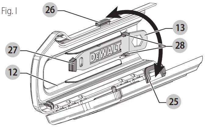
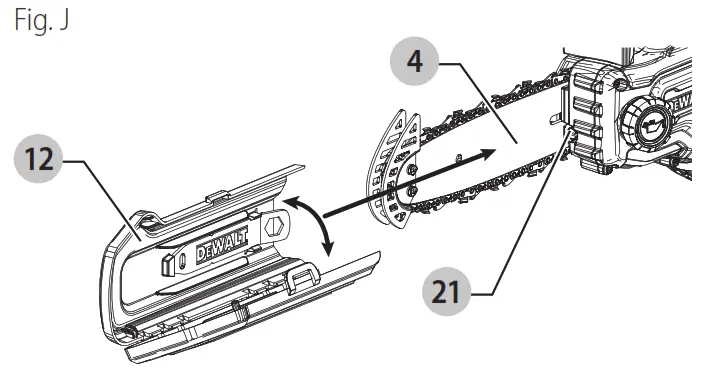
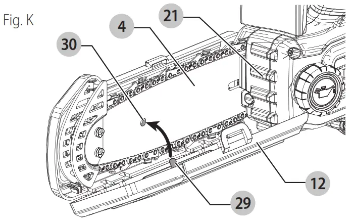
Scabbard and Wrench Storage (Fig. A, I–K)
The scabbard 12 has two functions, to cover the guide bar 4 when the tool is not in use and to store the wrench 13 .scabbard
- To open scabbard 12, lift up latch 25 and pull the two halves apart.
- Fit the scabbard 12 onto the guide bar 4 as shown in Fig. A, I–K. Ensure that the retaining pin 29 on the scabbard 12 aligns with the retaining hole 30 on the guide bar 4.
- To close scabbard 12, close the two halves and ensure that latch 25 is secured to notch 26.
Wrench
1. Open scabbard 12 to gain access to the wrench 13.
2. Remove wrench 13 by lifting the wrench to end up and away from the scabbard.
3. Store the wrench in the scabbard when finished. First, install the flat screwdriver end of the wrench into the retaining slot 27 and then press the wrench to end down until the retaining clips 28 firmly secure the wrench 13 in place.
Bar Tip Guard (Fig. A, K)![]() WARNING: Never operate the pruner without the bar tip guard properly mounted on the guide bar to prevent rotational kickback.
WARNING: Never operate the pruner without the bar tip guard properly mounted on the guide bar to prevent rotational kickback.
The bar tip guard 6 reduces the chance of chain 5 at the end of the guide bar 4 from coming into contact with objects which may cause the bar and chain to kick back toward the operator. In addition to reducing the chance of kickback, the bar tip guard 6 will reduce the chance of the chain from touching the ground.
Transporting Pruner (Fig. A, K)
- Always turn the unit off, remove the battery, and cover guide bar 4 with the scabbard 12 when transporting the pruner.
OPERATION
![]() WARNING: To reduce the risk of serious personal injury, turn the unit off and remove the battery pack before making any adjustments or removing/ installing attachments or accessories. An accidental start‑up can cause injury.
WARNING: To reduce the risk of serious personal injury, turn the unit off and remove the battery pack before making any adjustments or removing/ installing attachments or accessories. An accidental start‑up can cause injury.
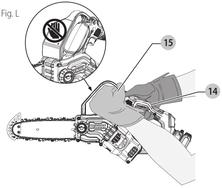
Proper Hand Position (Fig. A, L)![]() WARNING: To reduce the risk of serious personal injury, ALWAYS use proper hand position as shown. keeps
WARNING: To reduce the risk of serious personal injury, ALWAYS use proper hand position as shown. keeps
- Always turn the unit off, remove the battery, and cover guide bar 4 with the scabbard 12 when transporting the pruner. WARNING: To reduce the risk of serious personal injury, ALWAYS hold securely in anticipation of a sudden reaction.
Proper hand position requires the left hand on the front handle 15, under the front hand guard 3, with the right hand on the rear handle 14.
Note: DO NOT hold the saw by the front hand guard 3.
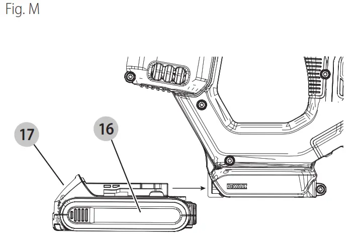
Installing and Removing the Battery Pack (Fig. M)![]() WARNING: Ensure the tool/appliance is in the off position before inserting the battery pack.
WARNING: Ensure the tool/appliance is in the off position before inserting the battery pack.
Note: For best results, make sure your battery pack is fully charged.
- To install the battery pack 16 into the tool handle, align the battery pack with the rails inside the tool’s handle and slide it into the handle until the battery pack is firmly seated in the tool and ensure that it does not disengage.
- To remove the battery pack from the tool, press the release button 17 and firmly pull the battery pack out of the tool handle. Insert it into the charger as described in the charger section of this manual.
Operating the Pruner (Fig. A)![]() WARNING: Read and understand all instructions.
WARNING: Read and understand all instructions.
Failure to follow all instructions listed below may result in electric shock, fire, and/or serious personal injury.
- Guard Against Kickbacks which can result in severe injury or death. See Important Safety Instructions guard Against Kickback, to avoid the risk of kickback.
- Do not overreach. Do not cut above chest height. Make sure your footing is firm. Keep feet apart. Divide your weight evenly on both feet.
- Use a firm grip with your left hand on the front handle 15 and your right hand on the rear handle 14 so that your body is to the left of the guide bar.
![]() WARNING: Do not hold the pruner by the front-hand guard. Keep the elbow of the left arm locked so that the left arm is straight to withstand a kickback.
WARNING: Do not hold the pruner by the front-hand guard. Keep the elbow of the left arm locked so that the left arm is straight to withstand a kickback.![]() WARNING: Never use a cross‑handed grip (left hand on the rear handle and right hand on the front handle).
WARNING: Never use a cross‑handed grip (left hand on the rear handle and right hand on the front handle).![]() WARNING: Never allow any part of your body to be in line with the guide bar when operating the chain pruner.
WARNING: Never allow any part of your body to be in line with the guide bar when operating the chain pruner.
- Never operate the pruner while in a tree, in an awkward position, or on a ladder or other unstable surface. You may lose control of the pruner causing severe injury.
- Keep the pruner running at full speed the entire time you are cutting.
- Allow the chain to cut for you. Exert only light pressure.
Do not put pressure on the pruner at end of the cut.
![]() WARNING: When not in use always have the chain brake (if equipped) engaged, the unit turned off, and remove the battery pack.
WARNING: When not in use always have the chain brake (if equipped) engaged, the unit turned off, and remove the battery pack.![]() WARNING: Never operate the pruner without the bar tip guard properly mounted on the guide bar to prevent rotational kickback.
WARNING: Never operate the pruner without the bar tip guard properly mounted on the guide bar to prevent rotational kickback.
ON/OFF Switch (Fig. A)![]() WARNING: Never attempt to lock a switch in the ON position.
WARNING: Never attempt to lock a switch in the ON position.
Always be sure of your footing and grip the pruner firmly with both hands with the thumb and fingers encircling both handles.
- To turn the unit on, push down on the lock-off lever 2, shown in Fig. A, and squeeze the trigger switch 1. Once the unit is running, you may release the lock-off lever.
- To keep the unit running you must continue to squeeze the trigger switch 1.
- To turn the unit off, release the trigger switch 1.
Note: If too much force is applied while making a cut the pruner will turn off. To restart the pruner, you must release the lock off lever 2 and the trigger switch 1 before the pruner will restart. Begin your cut again this time with less force. Allow the pruner to cut at its own pace.
Common Cutting Techniques Limbing
Removing the branches from a fallen tree. When limbing, leave larger lower limbs to support the log off the ground.
Remove the small limbs in one cut. Branches under tension should be cut from the bottom of the branch towards the top to avoid binding the pruner as shown below. Trim limbs from opposite sides keeping the tree stem between you and the pruner. Never make cuts with a pruner between your legs or straddle the limb to be cut.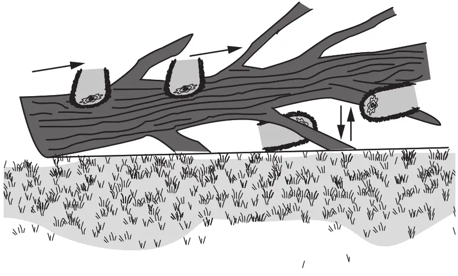
Bucking![]() WARNING: Recommend that first-time users should practice cutting on a pruner horse. Cutting a felled tree or log into lengths. How you should cut depends on how the log is supported. Use a pruner horse whenever possible as shown below.
WARNING: Recommend that first-time users should practice cutting on a pruner horse. Cutting a felled tree or log into lengths. How you should cut depends on how the log is supported. Use a pruner horse whenever possible as shown below.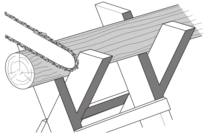
- Always start a cut with the pruner chain running at full speed.
- Place the ribbed bumper 21 of the pruner behind the area of the initial cut as shown below.
- Turn the pruner on then rotate the pruner chain and bar down into the tree, using the ribbed bumper as a hinge.
- Once the pruner gets to a 45 ° angle, level the pruner again and repeat the steps until you cut fully through.
- When the tree is supported along its entire length, make a cut from the top (over a buck), but avoid cutting the earth as this will dull your pruner quickly.
CUT FROM THE TOP (OVERBECK) AND AVOID CUTTING EARTH
• When supported at one end first, cut 1/3 the diameter from the underside (Funderburk). Then make the finishing cut by overbooking to meet the first cut as shown below.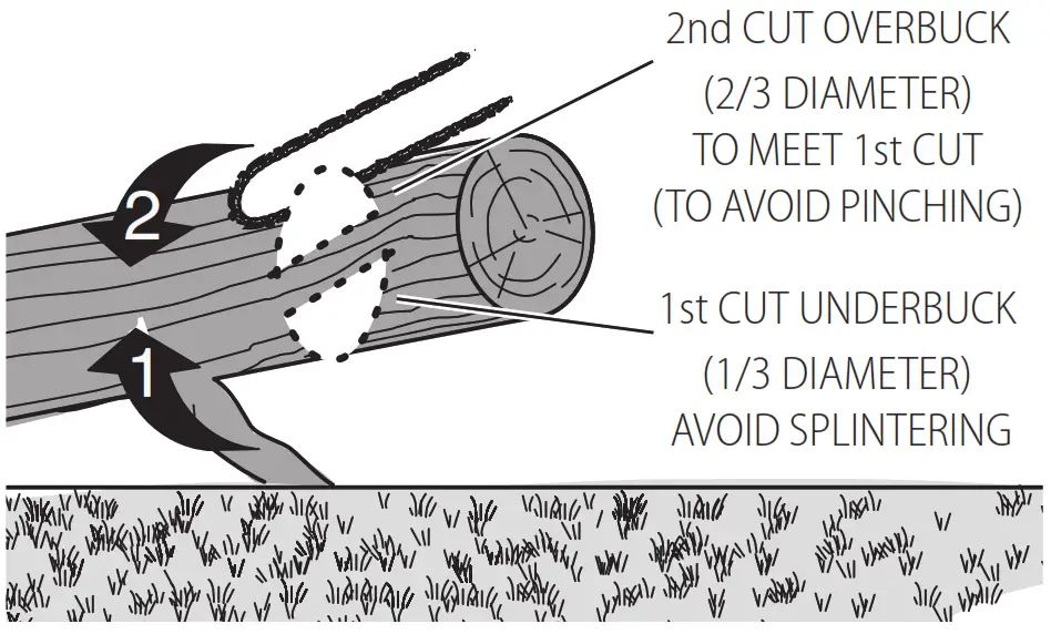
• When supported at both ends. First, cut 1/3 down from the top overbook. Then make the finished cut by under-bucking the lower 2/3 to meet the first cut as shown below.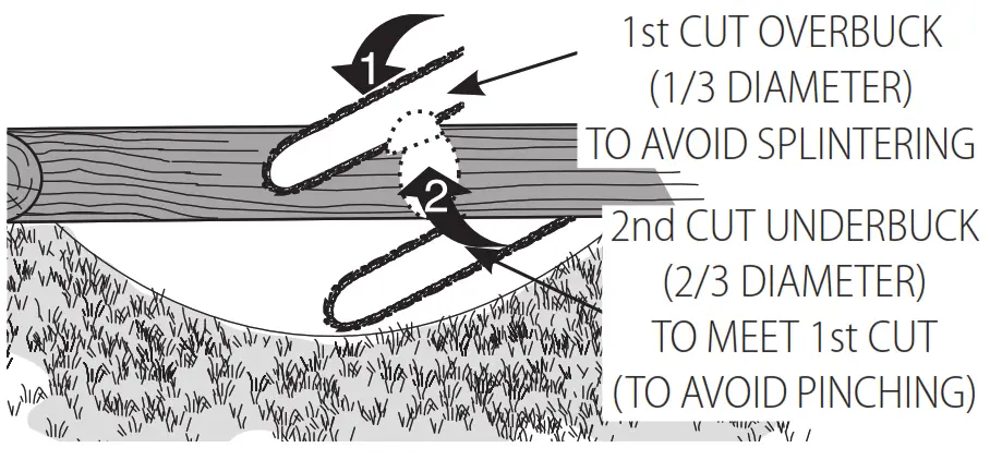
• When on a slope always stand on the uphill side of the log. When “cutting through”, to maintain complete control reduce the cutting pressure near the end of the cut without relaxing your grip on the pruner handles. Don’t let the chain contact the ground. After completing the cut, wait for the pruner chain to stop before you move the pruner. Always stop the motor before moving from cut to cut.
MAINTENANCE
![]() WARNING: To reduce the risk of serious personal injury, turn the unit off and remove the battery pack before making any adjustments or removing/ installing attachments or accessories. An accidental start‑up can cause injury.
WARNING: To reduce the risk of serious personal injury, turn the unit off and remove the battery pack before making any adjustments or removing/ installing attachments or accessories. An accidental start‑up can cause injury.
Your DeWALT power tool has been designed to operate over a long period of time with a minimum of maintenance. Continuous satisfactory operation depends upon proper tool care and regular cleaning.
Cleaning
![]() WARNING: Blow dirt and dust out of all air vents with clean, dry air at least once a week. To minimize the risk of eye injury, always wear ANSI Z87.1-approved eye protection when performing this procedure.
WARNING: Blow dirt and dust out of all air vents with clean, dry air at least once a week. To minimize the risk of eye injury, always wear ANSI Z87.1-approved eye protection when performing this procedure.![]() WARNING: Never use solvents or other harsh chemicals for cleaning the non‑metallic parts of the tool. These chemicals may weaken the plastic materials used in these parts. Use a cloth dampened only with water and mild soap. Never let any liquid get inside the tool; never immerse any part of the tool in a liquid.
WARNING: Never use solvents or other harsh chemicals for cleaning the non‑metallic parts of the tool. These chemicals may weaken the plastic materials used in these parts. Use a cloth dampened only with water and mild soap. Never let any liquid get inside the tool; never immerse any part of the tool in a liquid.
Saw Chain and Guide Bar
After every few hours of use, remove the sprocket cover, guide bar, and chain and clean thoroughly using a soft bristle brush. Ensure the oiling hole on the bar is clear of debris.
Sprocket and Sprocket Cover (Fig. A, F, H)![]() CAUTION: Sharp chain. Always wear protective gloves when handling the chain. The chain is sharp and can cut you when it is not running.
CAUTION: Sharp chain. Always wear protective gloves when handling the chain. The chain is sharp and can cut you when it is not running.![]() WARNING: Sharp moving chain. To prevent accidental operation, ensure the battery is removed from the tool is unplugged before performing the following operations. Failure to do this could result in serious personal injury.
WARNING: Sharp moving chain. To prevent accidental operation, ensure the battery is removed from the tool is unplugged before performing the following operations. Failure to do this could result in serious personal injury.
- Place the saw on a flat, firm surface.
- Remove sprocket cover 7 as described in Installing the Guide Bar and Saw Chain section.
- Wearing protective gloves, use a clean, soft bristle brush to wipe away any sawdust, sticks, vines, or other debris that may have been collected inside the sprocket cover 7 and around the chain 5 or sprocket 22.
- Rotate the chain tension screw 9 using the flat screwdriver end of the wrench 13. Turning the screw counterclockwise allows the guide bar 4 to recede and reduces the tension on the chain so that it may be removed.
- Wearing protective gloves, grasp the saw chain and guide bar and lift them away from the tool.
- Wearing protective gloves, use a clean, soft bristle brush to wipe away any sawdust or other debris that may have been collected on guide bar 4 and around chain 5.
- Install the chain, guide bar, and sprocket cover 7 as described in Installing the Guide Bar and Saw Chain, Replacing the Saw Chain sections, and adjusting chain tension properly before use as described in the Adjusting Chain Tension section.
Accessories
![]() WARNING: Since accessories, other than those offered by DeWALT, have not been tested with this product, the use of such accessories with this product could be hazardous. To reduce the risk of injury, only DeWALT-recommended accessories should be used with this product.
WARNING: Since accessories, other than those offered by DeWALT, have not been tested with this product, the use of such accessories with this product could be hazardous. To reduce the risk of injury, only DeWALT-recommended accessories should be used with this product.
Recommended accessories for use with your product are available at extra cost from your local dealer or authorized service center. If you need assistance in locating any accessory, please contact DeWALT call 1‑800‑4‑DeWALT (1‑800‑433‑9258) or visit our website: www.dewalt.com
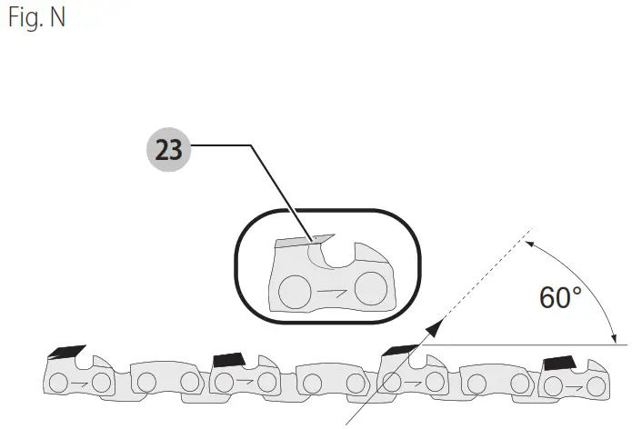
Saw Chain Sharpening (Fig. N–P)![]() CAUTION: Sharp chain. Always wear protective gloves when handling the chain. The chain is sharp and can cut you when it is not running.
CAUTION: Sharp chain. Always wear protective gloves when handling the chain. The chain is sharp and can cut you when it is not running.![]() WARNING: Sharp moving chain. To prevent accidental operation, ensure that battery is removed from the tool before performing the following operations. Failure to
WARNING: Sharp moving chain. To prevent accidental operation, ensure that battery is removed from the tool before performing the following operations. Failure to
do this could result in serious personal injury.![]() WARNING: Do not over-file chain rakers, this will increase the risk of kickback. If the chain has been sharpened more than four times, replace it. Each time the chain is sharpened, it loses some of the low kickback qualities and extra caution should be used.
WARNING: Do not over-file chain rakers, this will increase the risk of kickback. If the chain has been sharpened more than four times, replace it. Each time the chain is sharpened, it loses some of the low kickback qualities and extra caution should be used.
It is recommended that a saw chain be sharpened no more than four times.
Note: The cutters will dull immediately if they touch the ground/dirt or a nail while cutting.
To get the best possible performance from your pruner it is important to keep the teeth of the saw chain sharp. Follow these helpful tips for proper saw chain sharpening:
- For best results use an 11/64″ (4.5mm) file and a file holder or filing guide to sharpen your saw chain. This will ensure you always get the correct sharpening angles.
- Place the file holder flat on the top plate and depth the gauge of the cutter.
- Keep the correct top plate 23 filing angle line of 30 ° on your file guide parallel with your chain (file at 60 ° from the chain viewed from the side) as shown in Fig. N.
- Sharpen cutters on one side of the chain first. File from the inside of each cutter to the outside. Then turn your saw around and repeat the processes (2, 3, 4) for cutters on the other side of the chain.
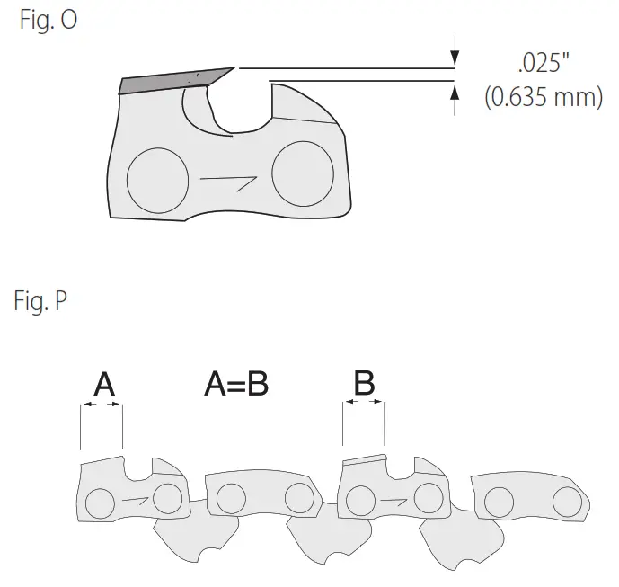
Note: Use a flat file to file the tops of the rakers (a portion of chain link in front of the cutter) so they are about .025″ (.635 mm) below the tips of the cutters as shown in Fig. O. Keep all cutter lengths equal as shown in Fig. P. - If damage is present on the chrome surface of the top plates or side plates, file back until such damage is removed. CAUTION: After filing, the cutter will be sharp, use extra caution during this process.
Repairs
The charger and batteries are not serviceable. There are no serviceable parts inside the charger or battery pack.![]() WARNING: To assure product SAFETY and RELIABILITY, repairs, maintenance, and adjustment (including brush inspection and replacement, when applicable) should be performed by a DeWALT factory service center or a DeWALT-authorized service center. Always use identical replacement parts.
WARNING: To assure product SAFETY and RELIABILITY, repairs, maintenance, and adjustment (including brush inspection and replacement, when applicable) should be performed by a DeWALT factory service center or a DeWALT-authorized service center. Always use identical replacement parts.
Register Online
Thank you for your purchase. Register your product now for:
- WARRANTY SERVICE: Registering your product will help you obtain more efficient warranty service in case there is a problem with your product.
- CONFIRMATION OF OWNERSHIP: In case of an insurance loss, such as fire, flood, or theft, your registration of ownership will serve as your proof of purchase.
- FOR YOUR SAFETY: Registering your product will allow us to contact you in the unlikely event a safety notification is required under the Federal Consumer Safety Act.
- Register online at www.dewalt.com.
Three-Year Limited Warranty
For warranty terms, go to https://www.dewalt.com/Legal/Warranty/3‑Year‑Limited‑Warranty.
To request a written copy of the warranty terms, contact:
Customer Service at DeWALT Industrial Tool Co., 701 East Joppa Road, Towson, MD 21286 or call 1‑800‑4‑DeWALT (1‑800‑433‑9258).
Latin America: This warranty does not apply to products sold in Latin America. For products sold in Latin America, see country-specific warranty information contained in the packaging, call the local company or see the website for warranty information.
FREE WARNING lABEl REPlACEMENT: If your warning labels become illegible or are missing, call 1‑800‑4‑DeWALT (1‑800‑433‑9258) for a free replacement.
DCCS623 TROUBLESHOOTING
BE SURE TO FOllOW SAFETY RUlES AND INSTRUCTIONS
For assistance with your product, visit our website at www.dewalt.com for a list of service centers, or call DeWALT at 1‑800‑4‑DeWALT (1‑800‑433‑9258).
| Problem | Solution |
| The unit will not start. | • Check battery installation. • Check battery charging requirements. • Check that lock off is fully pushed down prior to moving the main trigger. |
| The unit shuts down in use. | • Charge battery. • Unit is being forced. Restart and apply less pressure. |
| The battery will not charge. | • Insert the battery into the charger until the red charging light illuminates. • Plug the charger into a working outlet. Refer to Important Charging Notes for more details. • Check the current at the receptacle by plugging an appliance. • Check to see if the receptacle is connected to a light switch that turns the power off when you turn out the lights. • Move the charger and appliance to a surrounding air temperature of above 40 °F (4.5 °C) or below 104 °F (+40 °C). |
| The bar / Chain overheated. | • Refer to the Adjusting Chain Tension section. • Refer to the Chain Oiling section. |
| The chain is loose. | • Refer to the Adjusting Chain Tension section. |
| Poor cut quality. | • Refer to the Adjusting Chain Tension section. Note: Excessive tension leads to excessive wear and reduction in the life of the bar and chain. Lubricate before each cut. Refer to Replacing the Saw Chain and Saw Chain Sharpening section. |
| The unit runs but does not cut. | • Chain could be installed backward. Refer to the sections for installing and removing chains. |
| The unit does not have oil. | • Refill the oil reservoir. • Clean guide bar, sprocket, and sprocket cover. Refer to the Maintenance section. |
Compatible battery packs and chargers
| 20V Max* li‑ion | Battery Packs | DCB200, DCB201, DCB203, DCB203G, DCB204, DCB204BT**, DCB205, DCB205G, DCB205BT**, DCB206, DCB208, DCB210, DCB230, DCB240, DCBP034, DCBP520 |
| Chargers | DCB103, DCB104, DCB107, DCB112, DCB113, DCB115, DCB118, DCB132, DCB1102, DCB1104, DCB1106, DCB1112 | |
| 60V Max* li‑ion | Battery Packs | DCB606, DCB609, DCB609G, DCB612 |
| Chargers | DCB103, DCB104, DCB107, DCB112, DCB113, DCB115, DCB118, DCB132, DCB1102, DCB1104, DCB1106, DCB1112 |
* Maximum initial battery voltage (measured without a workload) is 20, 60, or 120 volts. The nominal voltage is 18, 54, or 108. (120V Max* is based on using 2 DeWALT 60V Max* lithium‑ion batteries combined.)
NOTE: The Bluetooth® word mark and logos are registered trademarks owned by the Bluetooth®, SIG, Inc. and any use of such marks by DeWALT is under license. Other trademarks and trade names are those of their respective owners.![]() WARNING: Use of any other battery packs may create a risk of injury and fire.
WARNING: Use of any other battery packs may create a risk of injury and fire.
DeWALT Industrial Tool Co. 701 East Joppa Road, Towson, MD 21286
Copyright © 2022
The following are trademarks for one or more DeWALT power tools: the yellow and black color scheme, the “D” shaped air intake grill, the array of pyramids on the handgrip, the kit box configuration, and the array of lozenge‑shaped humps on the surface of the tool.
NA130412 ![]()


