![]()
Quick Start Guide
__________________________
![]() -PRO20-HDMI-R100 2xMM-2xDUO
-PRO20-HDMI-R100 2xMM-2xDUO![]() -PRO20-HDMI-R100 2xMM-QUAD
-PRO20-HDMI-R100 2xMM-QUAD![]() -PRO20-HDMI-R100 2xSM-2xDUO
-PRO20-HDMI-R100 2xSM-2xDUO![]() -PRO20-HDMI-R100 2xSM-QUAD
-PRO20-HDMI-R100 2xSM-QUAD![]() -PRO20-HDMI-R100 2xSM-BiDi-DUO
-PRO20-HDMI-R100 2xSM-BiDi-DUO
Important Safety Instructions
Please read the supplied safety instruction document before using the product and keep it available for future reference.
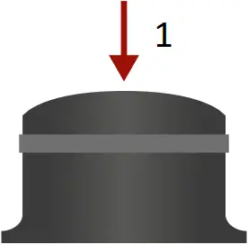
![]() The extender is Class 1 laser product.
The extender is Class 1 laser product.
Introduction
UBEX (Ultra Bandwidth Extender) product family offers a new optical solution allowing 4K@60Hz 4:4:4 uncompressed signal extension with extra low latency for the users. We use packet-based transmission instead of the conventional method.
Box Contents

UBEX R-series endpoint device

Power cable with Neutrik powerCON connector

Safety and warranty info, Quick Start Guide
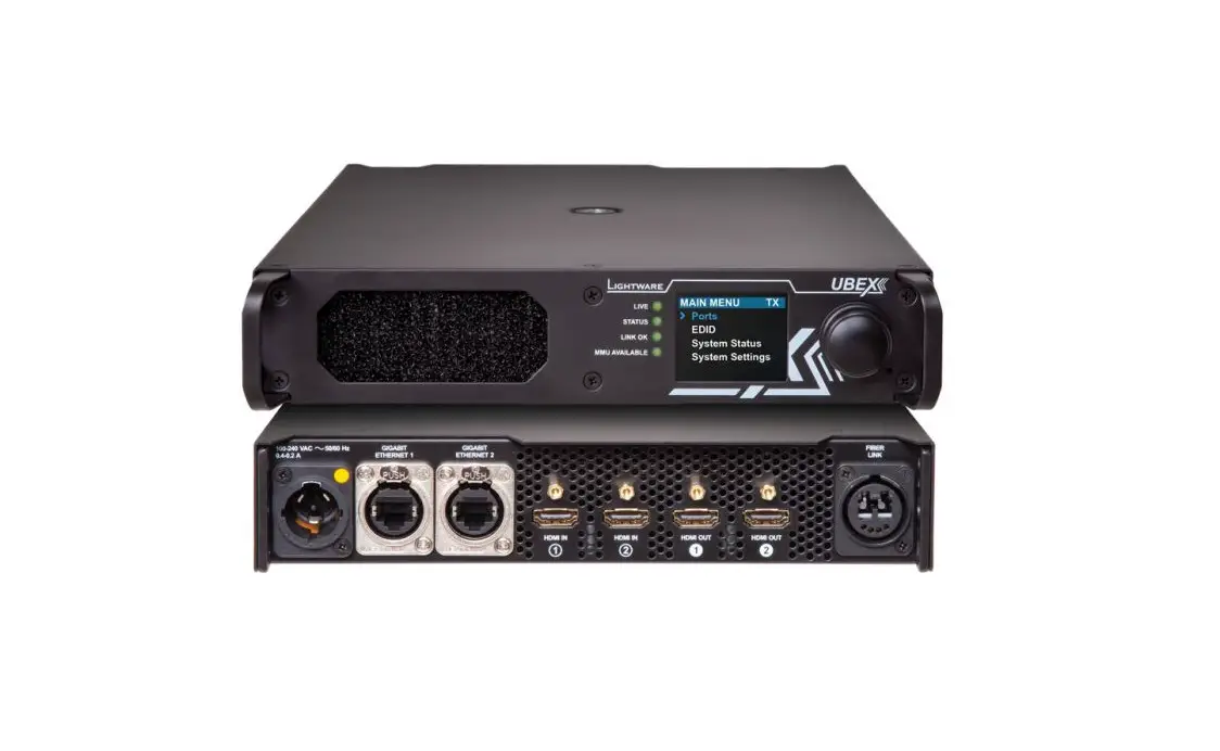
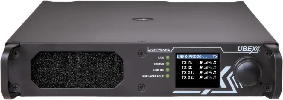
Front View – All Models

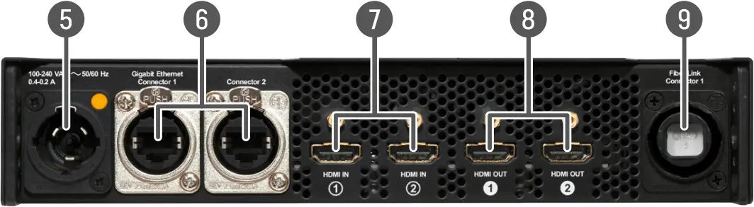
Rear View – 2xMM-QUAD / 2xSM-QUAD
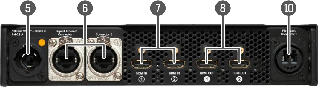
Rear View – 2xSM-BiDi-DUO
Rear View – 2xMM-2xDUO / 2xSM-2xDUO
| (1) | Status LEDs | The LEDs give immediate feedback about the recent status of the extender. |
| (2) | LCD screen | LCD screen showing the most important settings and parameters in the front panel menu. The available settings and information depends on the current application mode (Extender mode or Matrix mode). |
| (3) | Jog dial control knob | Easy setting and menu navigation by the jog dial control. Keep dial and click while getting feedback on the LCD. |
| (4) | Reset button | Reboots the device (the same as disconnecting from the power source and reconnecting again). |
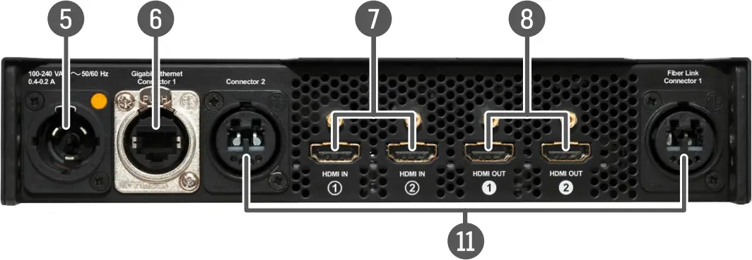
| (5) | Neutrik powerCON AC connector | Neutrik powerCON TRUE1 NAC3MPX-WOT connector accepting 100-240 V, 50 or 60 Hz. |
| (6) | Neutrik etherCON Ethernet connectors | Neutrik etherCON NE8FDV-YK locking RJ45 connectors for 1 Gbps Ethernet connections to control the device, for user Ethernet access, and firmware upgrade purpose. |
| (7) | HDMI input ports | HDMI input ports with HDMI 2.0 support for source devices. |
| (8) | HDMI output ports | HDMI output ports with HDMI 2.0 support for sink devices. |
| (9) | Neutrik opticalCON QUAD optical connector | Neutrik opticalCON QUAD NO4FDW-A singlemode or multimode fiber optical connector.
|
| (10) | Neutrik opticalCON DUO BiDi optical connector | Neutrik opticalCON DUO NO2-4FDW-A singlemode fiber optical connector with BiDi support. The connector does not support the Neutrik opticalCON crossed fiber wiring (A-A; B-B) cable. Please use standard (A-B) cable only. |
| (11) | Neutrik opticalCON DUO optical connector | 2x Neutrik opticalCON DUO NO2-4FDW-A singlemode or multimode fiber optical connector.
|
Front Panel Operation
Navigation in the LCD Menu
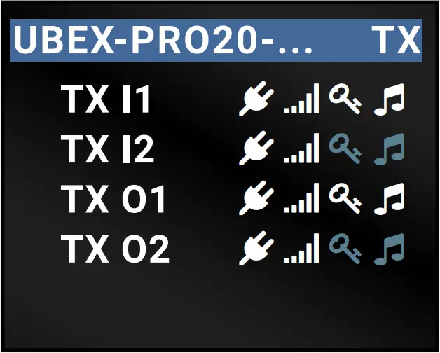
The front panel has a color LCD showing the most important settings and parameters. The jog dial control knob can be used to navigate between the menu items or change the value of a parameter (in case of TX, RX, or TRX as well). The knob can be pressed to enter a menu or edit/set a parameter.
Menu navigation & change parameter

- Turn
Menu selection & set parameter
- Press
The LCD Menu in Extender and Matrix Modes
The menu structure is different in Extender and Matrix mode. The following settings are not available in the LCD menu of the endpoint in Matrix mode but they can be set in the Matrix Management Unit:
- Video settings – TX/RX/TRX input/output settings
- EDID operations – EDID switching and saving
- Network settings – static and DHCP (dynamic) IP address settings
- Reloading factory default values
![]() The Extender or Matrix mode is set automatically in the endpoint device. If the device detects direct connection with another endpoint device at the other side of the connection, the mode is set to Extender mode; if the device is managed by the MMU, the mode is set to Matrix mode.
The Extender or Matrix mode is set automatically in the endpoint device. If the device detects direct connection with another endpoint device at the other side of the connection, the mode is set to Extender mode; if the device is managed by the MMU, the mode is set to Matrix mode.
Operation Mode Settings (only in Extender Mode)
The operation mode (TX/RX/TRX) of the unit can be changed from the LCD menu in a few steps.
- Navigate to the System settings / Operation mode / Switch mode… submenu and select the required mode: Transmitter, Receiver, or Transceiver.
- After the confirmation the unit resets. After booting up the device operates in the desired mode.
Set Static IP Address (only in Extender Mode)
The IP address of the endpoint can be set from the front panel:
- Navigate to the System settings / Network / DHCP menu and check the current state of the DHCP. If the setting is Enabled change it to Disabled. After this navigate to Save and press Enter.
- Navigate to the System settings / Network / Static IP menu, and select the Static IP address, Subnet mask, Static gateway options. Set the parameters by the front panel buttons according to your network requirements.
- Navigate to Save and press Enter.
Set Dynamic IP Address (DHCP) (only in Extender Mode)
- Navigate to the System settings / Network / DHCP menu and check the current state of the DHCP. If the setting is Disabled change it to Enabled.
- Navigate to the Save submenu (the last one of the Network menu) and press Enter.
Restore Factory Default Settings
Navigate to the System settings / Factory defaults menu and press Enter. After the confirmation the device reboots and the factory default values are reloaded in the device.
Mounting Options
Standard Rack Installation
- Two mounting holes on the front ears and two on the back of the chassis is for fastening two units to each other with 2x 2 pcs M4x8 mm screws. This way you get a one-rack wide and 1U high device.
- Fix the rack ears on left and right side as shown in the picture. The default position allows mounting the device as a standard rack unit.
To order rack mounting kit please contact [email protected].
See the detailed information about this mounting option in the user’s manual of the product.
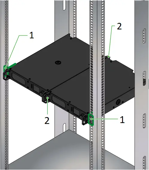
- Rack ear
- Fixing points (2 pcs M4x8 screws)
Truss Mounting
Mounting thread on top and on one of the sides is for safe and secure installation. Rigging the handles with a safety wire rope is highly recommended for safety reasons. (Truss mounting clamp and safety wire rope are not available at sales.)
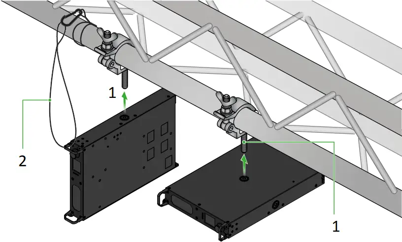
- M10x16mm screw
- Safety wire
See the detailed information about this mounting option in the user’s manual of the product.
Status LEDs
| LIVE | Transmitter / Receiver / Transceiver | ||
 | blinking | The device is powered and ready to use. | |
off | The device is not powered or out of operation. | ||
| STATUS | Transmitter / Receiver / Transceiver | ||
on | All measured temperature and voltage values are within the limits. | ||
| blinking | Measured temperature or voltage value is out of the limits. | |
off | The device is not powered or out of operation. | ||
| LINK OK | Transmitter / Receiver / Transceiver | ||
on | The connection is established on the fiber optical links and Link Aggregation is working. | ||
| blinking | The connection is established on the fiber optical links and LACP detection period is active. | |
off | No connection is established on one of the fiber optical links. | ||
| MMU AVAILABLE | Transmitter / Receiver / Transceiver | ||
on | Matrix mode is active; the communication is live between the endpoint and the Matrix Management Unit (MMU). | ||
| blinking | Matrix mode is active; no communication between the endpoint and the MMU | |
off | Extender mode is active; another endpoint is connected via the optical link. | ||
Connections
Transmitter (TX) Operation Mode
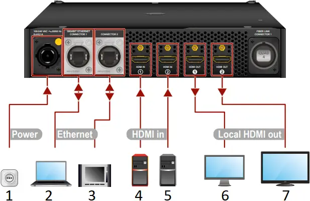
- Power
- Laptop
- Touch controller
- 4K PC
- PC
- Monitor
- 4K TV
Receiver (RX) Operation Mode
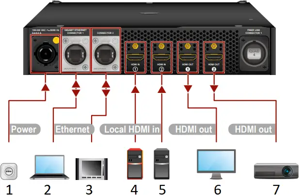
- Power
- Laptop
- Touch controller
- 4K PC
- PC
- Monitor
- Projector
![]() The HDMI input ports can be used as local input ports only.
The HDMI input ports can be used as local input ports only.
Transceiver (TRX) Operation Mode
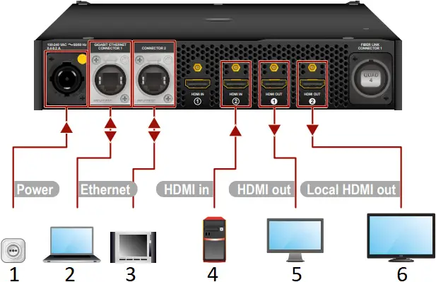
- Power
- Laptop
- Touch controller
- 4K PC
- Monitor
- 4K TV
![]() The HDMI input 1 port cannot accept AV signal when the device is configured as transceiver.
The HDMI input 1 port cannot accept AV signal when the device is configured as transceiver.
Fiber Optical Connections
- 2xSM-BiDi-DUO
- 2xMM-QUAD / 2xSM-QUAD
- 2xMM-2xDUO / 2xSM-2xDUO
Application Modes
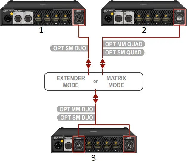
Extender Mode
Point-to-point connection between a transmitter and a receiver, or between two transceiver endpoint devices.
![]() In extender mode, an endpoint model can be connected to the same type of endpoint model. For example a 2xSM-2xDUO can be connected to another 2xSM-2xDUO.
In extender mode, an endpoint model can be connected to the same type of endpoint model. For example a 2xSM-2xDUO can be connected to another 2xSM-2xDUO.
![]()
- UBEX transmitter
- UBEX receiver
Matrix Mode
Virtual AV matrix with more transmitters, receivers, transceivers, and a Matrix Management Unit (MMU) which controls the AV network.
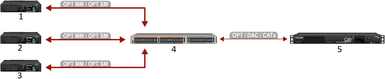
- UBEX transmitter
- UBEX receiver
- UBEX transceiver
- L3 network switch
- UBEX-MMU-X200 Matrix Management Unit
Transmitter (TX) Operation Mode | ||
| For all models | HDMI in | Connect the transmitter and the source devices (e.g. 4K PC, PC) using the HDMI input 1 and 2 ports by HDMI cables. |
| Local HDMI out | Connect the local sink devices (e.g. monitor, 4K TV) to the HDMI output 1 and 2 ports by HDMI cables. The output ports are local loopback ports: the same streams are transmitted which are received on the input ports. | |
| Ethernet | Optionally, connect the transmitter to a LAN in order to control the device. User Ethernet is also transmitted over the fiber optical interface so be sure not to create a network loop! | |
| Power | Connect the power adaptor to the AC input on the transmitter first, then to the AC power socket. | |
Receiver (RX) Operation Mode | ||
| For all models | Local HDMI in | Optionally, connect the UBEX receiver and the local source devices (e.g. PCs) using the HDMI input 1 and 2 ports by HDMI cables. |
| HDMI out | Connect the sink devices (e.g. monitor, projector) to the HDMI output 1 and 2 ports by HDMI cables. | |
| Ethernet | Optionally, connect the receiver to a LAN in order to control the device. User Ethernet is also transmitted over the fiber optical interface so be sure not to create a network loop! | |
| Power | Connect the power adaptor to the AC input on the receiver first, then to the AC power socket. | |
Transceiver (TRX) Operation Mode | ||
| For all models | HDMI in | Connect the transceiver and a source devices (e.g. 4K PC) using the HDMI input 2 port by an HDMI cable. |
| HDMI out | Connect a sink device (e.g. monitor) to the HDMI output 1 port by a HDMI cable. | |
| Local HDMI out | Connect a local sink (e.g. 4K TV) to the HDMI output 2 by an HDMI cable. The output port is a local loopback port: the same stream is transmitted which is received on the HDMI input 2 port. | |
| Ethernet | Optionally, connect the transceiver to a LAN in order to control the device. User Ethernet is also transmitted over the fiber optical interface so be sure not to create a network loop! | |
| Power | Connect the power adaptor to the AC input on the transceiver first, then to the AC power socket. | |
Fiber Optical Connections | ||
| 2xSM-BiDi- DUO | OPT SM DUO | Connect the device and the remote UBEX endpoint (Extender mode) / L3 network switch (Matrix mode) by a singlemode Neutrik opticalCON DUO BiDi or 2 pcs singlemode LC fiber optical cables. The connector does not support the Neutrik opticalCON crossed fiber wiring (A-A; B-B) cable. Please use standard (A-B) cable only. |
| 2xMM- QUAD | OPT MM QUAD | Connect the device and the remote UBEX endpoint (Extender mode) / L3 network switch (Matrix mode) by a multimode Neutrik opticalCON QUAD fiber optical cable. |
| 2xSM- QUAD | OPT SM QUAD | Connect the device and the remote UBEX endpoint (Extender mode) / L3 network switch (Matrix mode) by a singlemode Neutrik opticalCON QUAD fiber optical cable. |
| 2xMM- 2xDUO | OPT MM DUO | Connect the device and the remote UBEX endpoint(Extender mode) / L3 network switch (Matrix mode) by 2 pcs multimode Neutrik opticalCON DUO or 4 pcs multimode LC fiber optical cables. |
| 2xSM- 2xDUO | OPT SM DUO | Connect the device and the remote UBEX endpoint (Extender mode) / L3 network switch (Matrix mode) by 2 pcs singlemode Neutrik opticalCON DUO or 4 pcs singlemode LC fiber optical cables. |
Factory Default Settings
The following settings are applied in the device once the factory default settings are recalled:
GENERAL SETTINGS | |
System settings | |
| Application mode (Extender / Matrix) | Auto (the endpoint detects automatically the actual application mode) |
Network settings | |
| Static IP address – TX mode | 192.168.0.101 |
| Static IP address – RX mode | 192.168.0.102 |
| Static IP address – TRX mode | 192.168.0.101 |
| Subnet mask | 255.255.255.0 |
| Default gateway | 192.168.0.1 |
| DHCP | Disabled |
| LW3 command protocol port | 6107 |
| HTTP port | 80 |
HDMI PORT SETTINGS – TRANSMITTER MODE | |
HDMI input port properties | |
| Scaler mode – HDMI in 1 | Pass-through |
| FRC mode – HDMI in 2 | Pass-through |
| Color space converter – HDMI in 1 and 2 | No conversion |
| HDCP setting – HDMI in 1 and 2 | Enabled |
HDMI PORT SETTINGS – RECEIVER MODE | |
HDMI output port properties | |
| Scaler mode – HDMI out 1 | Pass-through |
| FRC mode – HDMI out 1 and 2 | Pass-through |
| Color space converter – HDMI out 1 and 2 | No conversion |
| Timing mode – HDMI out 1 and 2 | Free run |
| HDCP mode – HDMI out 1 and 2 | Auto |
HDMI PORT SETTINGS – TRANSCEIVER MODE | |
HDMI input 2 port properties | |
| FRC mode | Pass-through |
| Color space converter | No conversion |
| HDCP setting | Enabled |
HDMI output 1 port properties | |
| Scaler mode | Pass-through |
| FRC mode | Pass-through |
| Color space converter | No conversion |
| Timing mode | Free run |
| HDCP mode | Auto |
Installation – First Steps
Setting the Operation Mode
All endpoint devices are manufactured as transmitter (TX) by default. Set up the operation mode for the endpoints that are to be used as receivers (RX) or transceive rs (TRX) with the front panel LCD menu.
Connecting to the Devices over LAN
![]() Connecting the devices to the network using the factory default network settings might cause IP address conflict.
Connecting the devices to the network using the factory default network settings might cause IP address conflict.
Please follow the steps before connecting the endpoint devices to the network:
- Set different static IP addresses or set DHCP (dynamic IP address) on the front panel LCD menu or via the Lightware Device Controller (LDC) software.
- Establish connection between the endpoint devices over the fiber optical interface.
Software Control – Using Lightware Device Controller (LDC)
The device can be controlled from a computer through the Ethernet ports using Lightware Device Controller. Please download the application from www.lightware.com, install on a Windows PC or a macOS and establish connection to the device.
![]()
Further information on the device is available at www.lightware.com.
The User’s Manuals are also available via the QR codes below (Extender – left; Matrix – right):


Contact Us
[email protected]
+36 1 255 3800
[email protected]
+36 1 255 3810
Lightware Visual Engineering PLC.
Budapest, Hungary
Doc. ver.: 1.3
19210058


