![]()
SÉRIE 1450 – OPTILUX SERIES
A. SUSPENDED INSTALLATION – REMOTE DRIVER (1/4)
CR0, CR1, CR2
LT 1450 Optilux LED Profiles
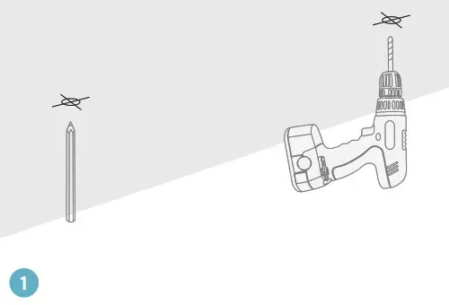
Choose and mark the mounting locations on the ceiling, drill holes if needed.
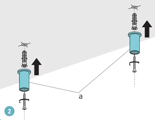
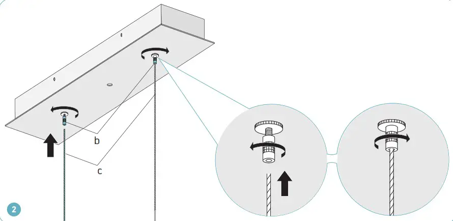
Secure cable couplers (a) on the ceiling using appropriate mounting screws #8 and anchors (not included).
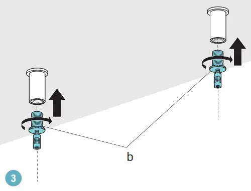
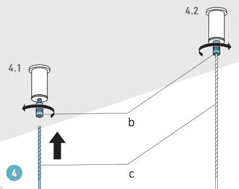
Screw the cable grippers (b) into the cable couplers on the ceiling.
Tighten to secure.
Loosen the stoppers on the cable grippers (b) and pass the suspension cables (c) all the way inside. Tighten the cable stoppers.
REMOTE DRIVER (2/4)
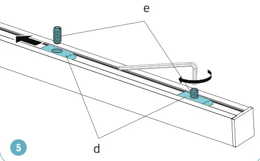
Adjust the 1/4”-20NC inserts (d) inside the upper channel of the extrusion to position them equal distance from both ends. Tighten the inserts using set screws (e) and Allen key.
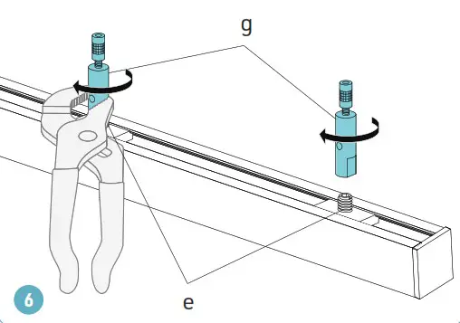
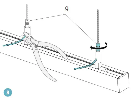
Assemble cable grippers (g) to the extrusion using the set screws (e) installed in the inserts. Tighten the cable grippers.
Loosen the stoppers on the cable grippers (g) and pass the suspension cables (c) into the cable grippers and out through the side exit holes. Adjust the cable length to the needed suspension height.
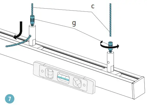
Tighten the stoppers of the cable grippers (g).
When the luminaire is well aligned, cut off the excess cable.
REMOTE DRIVER (3/4)
Make sure that the power is switched off at the electrical panel.
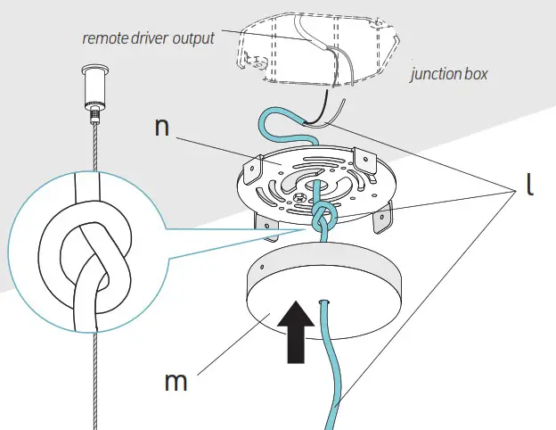
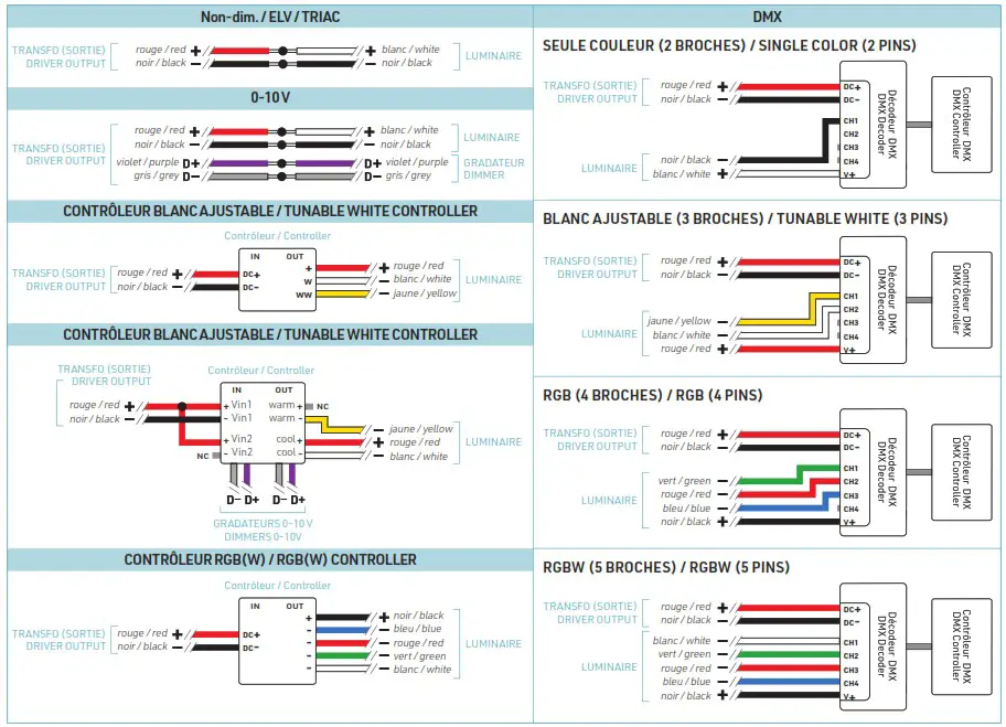
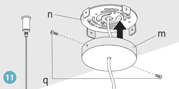
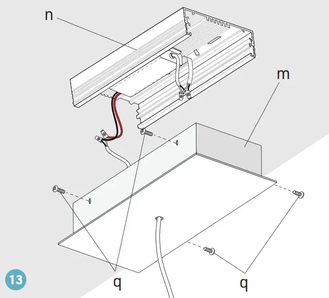
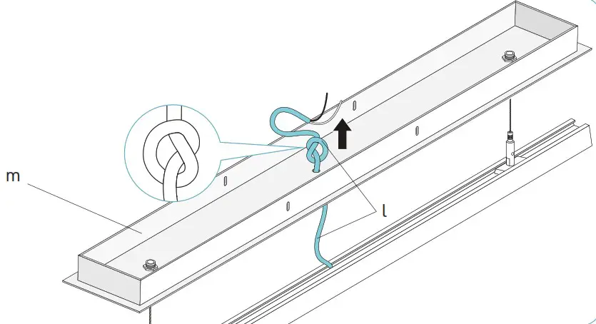
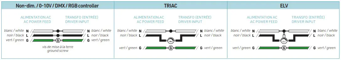
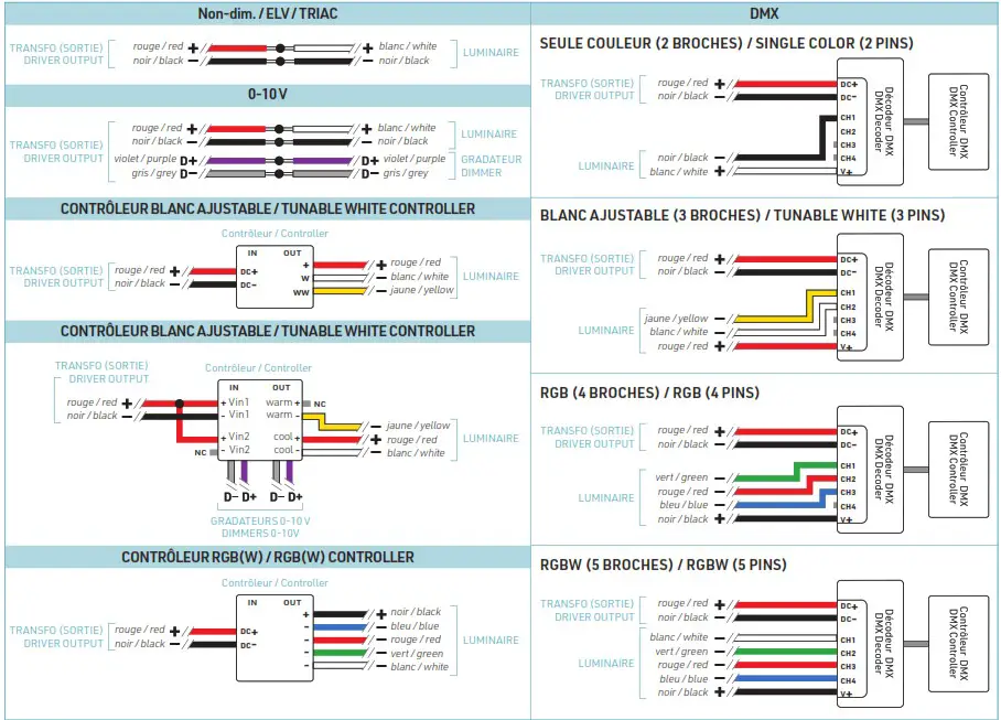
Pass the electrical wire (l) from the luminaire through the hole in the canopy (m), tie the wire into a knot to prevent it from being pulled out. Then pass the wire through the central hole in the mounting plate (n). Locate junction box (by others). Make electrical connections between the wire from the luminaire (l) and the output wire of the remote driver (by others). See the wiring diagrams below for different connection options depending on LED tape and dimmer types.
REMOTE DRIVER (4/4)
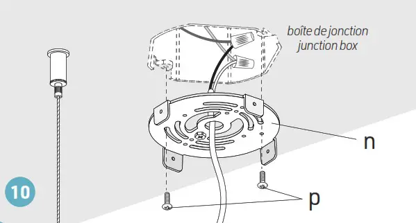
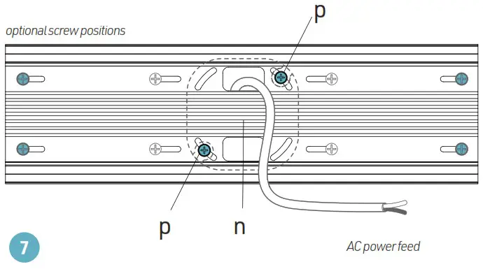
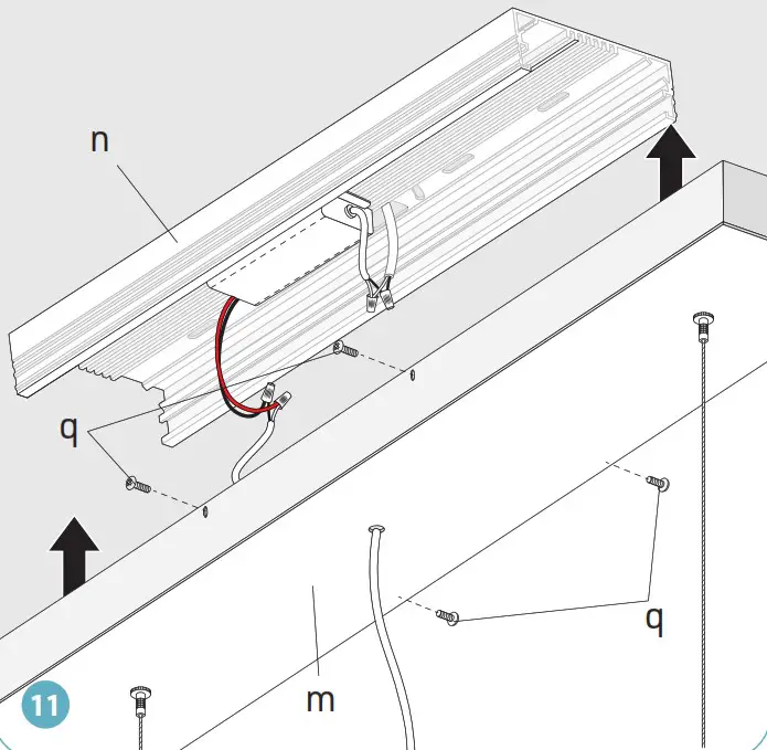
Assemble the mounting plate(n) to the junction box using provided screws (p).
Assemble the canopy (m) to the mounting plate (n) using provided screws (q).
![]() WARNING: RISK OF ELECTRIC SHOCK
WARNING: RISK OF ELECTRIC SHOCK
To prevent electric shock, power should be turned off from the electrical panel before installation or maintenance process.
INSTALLATION MUST COMPLY WITH ALL CURRENT NATIONAL AND LOCAL ELECTRICAL CODES.
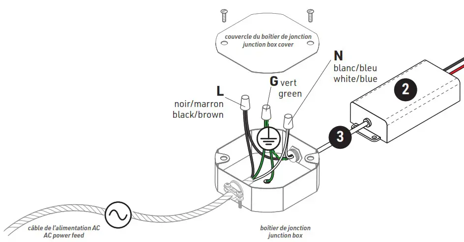
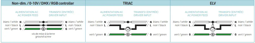
- Pass the main power feed (not included) and power supply input cable (3) into junction box (not included).
- Connect the white (N, Neutral) cables from the power feed and from the power supply.
- Connect the black (L, Live) cables from the power feed and from the power supply.
- Connect the copper, green or yellow (G, ground) wires from the power supply, power feed, and the junction box. Use appropriate twist-on connectors (not included).
- Install the junction box cover (not included).
![]() WARNING: Use only Class 2 rated components.
WARNING: Use only Class 2 rated components.
INTEGRATED DRIVER CANOPY (1/5)
CI0, CI1, CI2
Choose and mark the mounting locations on the ceiling, drill holes if needed.
Secure cable couplers (a) on the ceiling using appropriate mounting screws #8 and anchors (not included).
Screw the cable grippers (b) into the cable couplers on the ceiling.
Tighten to secure.
Loosen the stoppers on the cable grippers (b) and pass the suspension cables (c) all the way inside. Tighten the cable stoppers.
INTEGRATED DRIVER CANOPY (2/5)
Adjust the 1/4”-20NC inserts (d) inside the upper channel of the extrusion to position them equal distance from both ends. Tighten the inserts using set screws (e) and Allen key.
Assemble cable grippers (g) to the extrusion using the set screws (e) installed in the inserts. Tighten the cable grippers.
Loosen the stoppers on the cable grippers (g) and pass the suspension cables (c) into the cable grippers and out through the side exit holes. Adjust the cable length to the needed suspension height.
Tighten the stoppers of the cable grippers (g).
When the luminaire is well aligned, cut off the excess cable.
INTEGRATED DRIVER CANOPY (3/5)
![]() WARNING: RISK OF ELECTRIC SHOCK
WARNING: RISK OF ELECTRIC SHOCK
To prevent electric shock, power should be turned off from the electrical panel before installation or maintenance process.
INSTALLATION MUST COMPLY WITH ALL CURRENT NATIONAL AND LOCAL ELECTRICAL CODES.
Make sure that the power is switched off at the electrical panel.
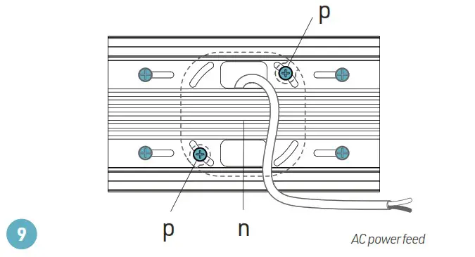
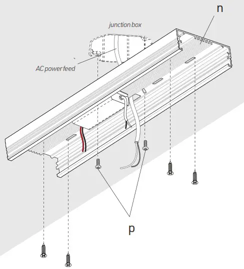
Locate junction box (not included). Pass the AC main power feed (not included) through the central hole in the mounting plate (n).
Assemble the mounting plate to the junction box using provided screws (p).
Thoroughly secure the mounting plate(n) to the ceiling using appropriate mounting screws #8 (not included).
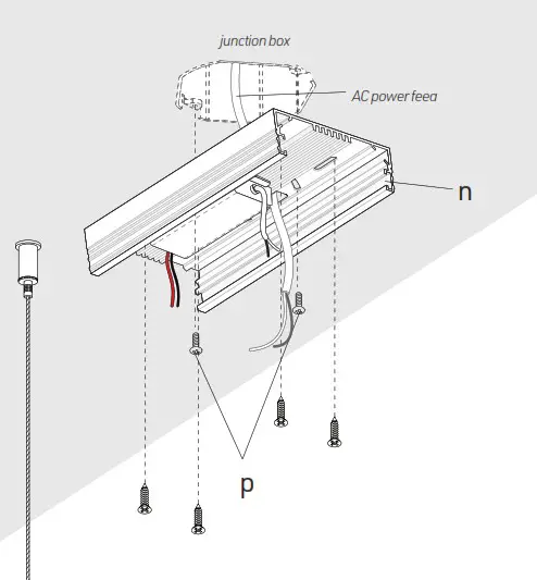
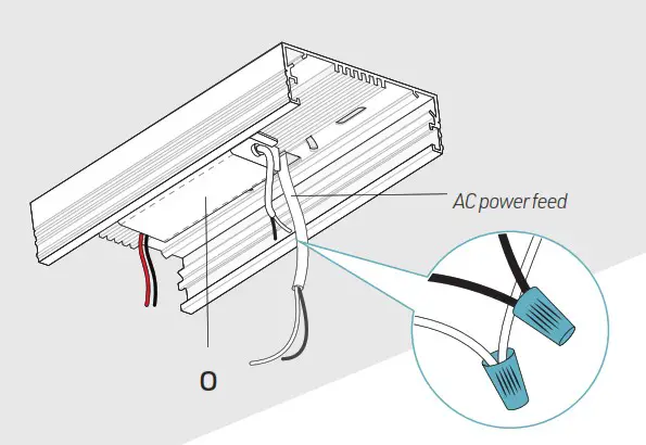
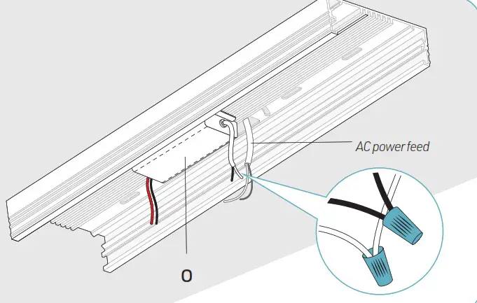
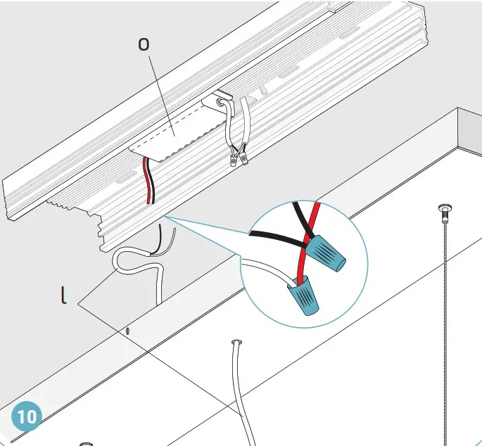
Make electrical connections between the driver input (o) and the main power feed (see wiring diagram on p.9).
INTEGRATED DRIVER CANOPY (4/5)
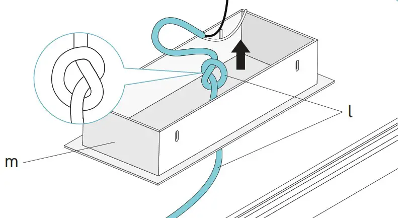
Pass the electrical wire (l) from the luminaire through the hole in the canopy (m). Adjust the electrical wire to the desired length. Tie the wire into a knot to prevent it from being pulled out.
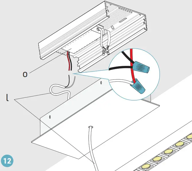
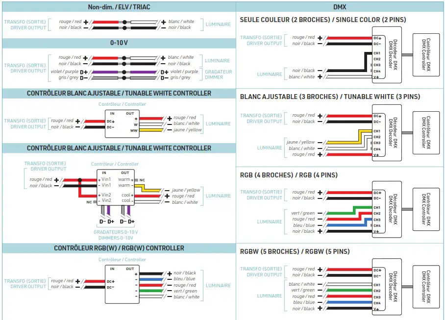
Make electrical connections between the driver output (o) and the luminaire electrical wire (l).
See the wiring diagrams p.9 for different connection options depending on LED tape and dimmer types.
Assemble the canopy (m) to the mounting plate (n) using provided screws (q).
INTEGRATED DRIVER CANOPY (5/5)
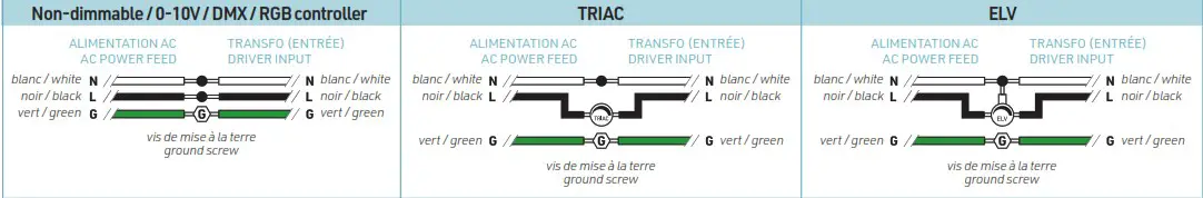
HIGH VOLTAGE CONNECTION BETWEEN THE POWER SUPPLY INPUT AND THE POWER FEED
LOW VOLTAGE CONNECTION BETWEEN THE POWER SUPPLY OUTPUT AND THE LUMINAIRE
![]() WARNING: Use only Class 2 rated components.
WARNING: Use only Class 2 rated components.
INTEGRATED DRIVER CANOPY (1/5)
CIK0, CIK1, CIK2
Insert cable grippers (b) into the mounting holes of the canopy (j). Secure the cable grippers using provided mounting nuts (a).
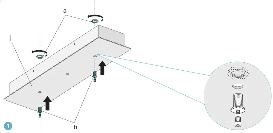
Loosen the stoppers on the cable grippers (b) and pass the suspension cables (c) all the way inside. Tighten the cable stoppers.
INTEGRATED DRIVER CANOPY (2/5)
Adjust the 1/4”-20NC inserts (d) inside the upper channel of the extrusion to position them equal distance from both ends. Tighten the inserts using set screws (e) and Allen key.
Assemble cable grippers (g) to the extrusion using the set screws (e) installed in the inserts. Tighten the cable grippers.
Loosen the stoppers on the cable grippers (g) and pass the suspension cables (c) into the cable grippers and out through the side exit holes. Adjust the cable length to the needed suspension height.
Tighten the stoppers of the cable grippers (g).
When the luminaire is well aligned, cut off the excess cable.
INTEGRATED DRIVER CANOPY (3/5)
![]() WARNING: RISK OF ELECTRIC SHOCK
WARNING: RISK OF ELECTRIC SHOCK
To prevent electric shock, power should be turned off from the electrical panel before installation or maintenance process.
INSTALLATION MUST COMPLY WITH ALL CURRENT NATIONAL AND LOCAL ELECTRICAL CODES.
Make sure that the power is switched off at the electrical panel.
Locate junction box (by others). Pass the AC main power feed (by others) through the central hole in the mounting plate (n). Assemble the mounting plate to the junction box using provided screws (p). Thoroughly secure the mounting plate(n) to the ceiling using appropriate mounting screws #8 and anchors if necessary (by others).
Make electrical connections between the driver input (o) and the main power feed (see wiring diagram on p.14).
INTEGRATED DRIVER CANOPY (4/5)
Pass the electrical wire (l) from the luminaire through the hole in the canopy (m). Adjust the electrical wire to the desired length. Tie the wire into a knot to prevent it from being pulled out.
Make electrical connections between the driver output (o) and the luminaire electrical wire (l).
See the wiring diagrams p.14 for different connection options depending on LED tape and dimmer types.
Assemble the canopy (m) to the mounting plate (n) using provided screws (q).
INTEGRATED DRIVER CANOPY (5/5)
HIGH VOLTAGE CONNECTION BETWEEN THE POWER SUPPLY INPUT AND THE POWER FEED
LOW VOLTAGE CONNECTION BETWEEN THE POWER SUPPLY OUTPUT AND THE LUMINAIRE
![]() WARNING: Use only Class 2 rated components.
WARNING: Use only Class 2 rated components.
www.lumentruss.com / 1 855 384 3384 / 1 514 903 5863 / 9221, Rue Edison, Montréal (Québec), H1J 1T4
LumenTruss reserves the rights to make changes to this document at any time without prior notice.


