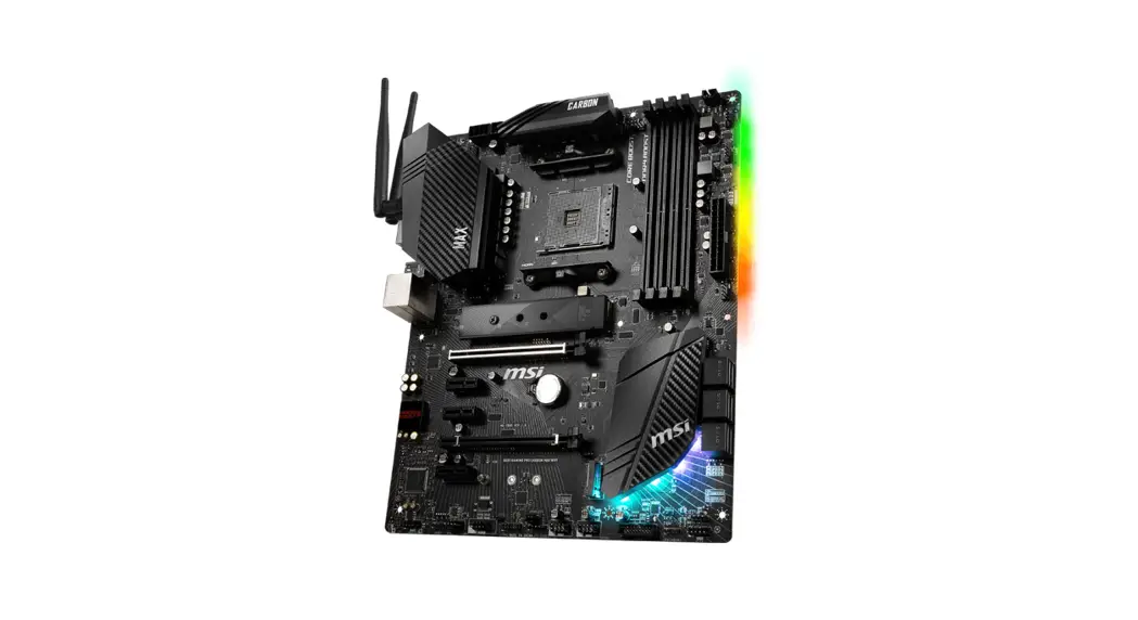
B450 Gaming Pro Carbon Max WiFi Motherboard
Quick Start
Thank you for purchasing the MSI® B450 GAMING PRO CARBON MAX WIFI motherboard. This Quick Start section provides demonstration diagrams about how to install your computer. Some of the installations also provide video demonstrations. Please link to the URL to watch it with the web browser on your phone or tablet. You may have even link to the URL by scanning the QR code.
Preparing Tools and Components
AMD® AM4 CPU
CPU Fan
Thermal Paste
DDR4 Memory
Power Supply Unit
Chassis
SATA DVD Drive
SATA Hard Disk Drive
Graphics Card
Phillips Screwdriver
A Package of Screws
Quick Start 1
Installing a Processor
1
3 2
5 4
6 2 Quick Start
8 9
7
Important
If you are installing the screw-type CPU heatsink, please follow the figure below to remove the retention module first and then install the heatsink.
1
2
3
Quick Start 3
Installing DDR4 memory
1
2 3
1
2 3
DIMMA2
4 Quick Start
DIMMB2 DIMMA2
DIMMB2 DIMMB1 DIMMA2 DIMMA1
Connecting the Front Panel Header
POPWOEWRELREHLDD-EDDL+ED
RESET SW POWER SW
Power LED Power Switch
–
-+
—
++
JFP1
2 1
+
10
9
Reserved
HDD LED Reset Switch
1
HDD LED +
2
3
HDD LED –
4
5
Reset Switch
6
7
Reset Switch
8
9
Reserved
10
Power LED + Power LED Power Switch Power Switch
No Pin
HDD LED POWER LED
HDD LED RESET SW
JFP1
HDD LED HDD LED + POWER LED POWER LED +
Quick Start 5
Installing the Motherboard 1 2
6 Quick Start
BAT1
Installing SATA Drives
2
1 3
5 4
Quick Start 7
Installing a Graphics Card
1
3 2
5 8 Quick Start
4 6
Connecting Peripheral Devices
Processor with integrated graphics
Quick Start 9
Connecting the Power Connectors
ATX_PWR1
CPU_PWR1
10 Quick Start
CPU_PWR2
Power On 2
1 3
4 Quick Start 11
Contents
Quick Start ………………………………………………………………………………………………. 1 Preparing Tools and Components……………………………………………………………….. 1 Installing a Processor………………………………………………………………………………… 2 Installing DDR4 memory ……………………………………………………………………………. 4 Connecting the Front Panel Header…………………………………………………………….. 5 Installing the Motherboard…………………………………………………………………………. 6 Installing SATA Drives………………………………………………………………………………… 7 Installing a Graphics Card ………………………………………………………………………….. 8 Connecting Peripheral Devices …………………………………………………………………… 9 Connecting the Power Connectors…………………………………………………………….. 10 Power On………………………………………………………………………………………………… 11
Safety Information………………………………………………………………………………….. 15 Specifications…………………………………………………………………………………………. 16
JCORSAIR1 Connector Specification …………………………………………………………. 21 Package contents …………………………………………………………………………………… 22 Block Diagram ………………………………………………………………………………………. 23 Rear I/O Panel ……………………………………………………………………………………….. 24
LAN Port LED Status Table……………………………………………………………………….. 24 Audio Ports Configuration ………………………………………………………………………… 24 Realtek Audio Console …………………………………………………………………………….. 25 Overview of Components ………………………………………………………………………… 28 Processor Socket…………………………………………………………………………………….. 30 DIMM Slots……………………………………………………………………………………………… 31 PCI_E1~5: PCIe Expansion Slots……………………………………………………………….. 32 M2_1~2: M.2 Slots (Key M) ……………………………………………………………………….. 33 SATA1~6: SATA 6Gb/s Connectors …………………………………………………………….. 34 JFP1, JFP2: Front Panel Connectors …………………………………………………………. 34 CPU_PWR1~2, ATX_PWR1: Power Connectors …………………………………………… 35 JUSB1~2: USB 2.0 Connectors………………………………………………………………….. 36 JUSB3: USB 3.2 Gen1 Connector ………………………………………………………………. 36 CPU_FAN1, PUMP_FAN1, SYS_FAN1~4: Fan Connectors…………………………….. 37 JAUD1: Front Audio Connector …………………………………………………………………. 37 JCI1: Chassis Intrusion Connector…………………………………………………………….. 38 JCOM1: Serial Port Connector ………………………………………………………………….. 38 JTPM1: TPM Module Connector………………………………………………………………… 39
12 Contents
JBAT1: Clear CMOS (Reset BIOS) Jumper ………………………………………………….. 39 JRGB1~2, JRAINBOW1: RGB LED connectors …………………………………………….. 40 JCORSAIR1: CORSAIR Connector ……………………………………………………………… 41 EZ Debug LED…………………………………………………………………………………………. 42
BIOS Setup …………………………………………………………………………………………….. 43 Entering BIOS Setup………………………………………………………………………………… 43 Resetting BIOS………………………………………………………………………………………… 44 Updating BIOS…………………………………………………………………………………………. 44 EZ Mode …………………………………………………………………………………………………. 46 Advanced Mode ………………………………………………………………………………………. 48 SETTINGS……………………………………………………………………………………………….. 49 Advanced………………………………………………………………………………………………… 49 Boot……………………………………………………………………………………………………….. 54 Security ………………………………………………………………………………………………….. 54 Save & Exit……………………………………………………………………………………………… 56 OC………………………………………………………………………………………………………….. 57 M-FLASH ……………………………………………………………………………………………….. 61 OC PROFILE ……………………………………………………………………………………………. 62 HARDWARE MONITOR……………………………………………………………………………… 63
Software Description………………………………………………………………………………. 64 Installing Windows® 10…………………………………………………………………………….. 64 Installing Drivers …………………………………………………………………………………….. 64 Installing Utilities ……………………………………………………………………………………. 64 APP MANAGER ……………………………………………………………………………………….. 65 LIVE UPDATE 6………………………………………………………………………………………… 66 COMMAND CENTER ………………………………………………………………………………… 68 GAMING APP…………………………………………………………………………………………… 72 X-BOOST ………………………………………………………………………………………………… 77 MYSTIC LIGHT…………………………………………………………………………………………. 79 MYSTIC LIGHT PARTY ………………………………………………………………………………. 83 SMART TOOL…………………………………………………………………………………………… 87 RAMDISK………………………………………………………………………………………………… 89 GAMING LAN MANAGER ………………………………………………………………………….. 90 Nahimic 3……………………………………………………………………………………………….. 92
RAID Configuration…………………………………………………………………………………. 95 Using AMD RAID Controller BIOS Configuration Utility………………………………… 95 Initialize Disks ………………………………………………………………………………………… 97
Contents 13
Create Arrays………………………………………………………………………………………….. 98 Delete Arrays ………………………………………………………………………………………….. 99 Swap Arrays………………………………………………………………………………………….. 100 Manage Spares ……………………………………………………………………………………… 101 Change the Controller Options………………………………………………………………… 102 Booting the system from an array……………………………………………………………. 102 Pausing the boot sequence for warning messages ……………………………………. 102 Change the Staggered Spinup Count ……………………………………………………….. 103 Using UEFI to create a 2.2TB RAID ………………………………………………………….. 104 Installing RAID Driver…………………………………………………………………………….. 105 Troubleshooting …………………………………………………………………………………… 106 Regulatory Notices……………………………………………………………………………….. 107
14 Contents
Safety Information
y The components included in this package are prone to damage from electrostatic discharge (ESD). Please adhere to the following instructions to ensure successful computer assembly. y Ensure that all components are securely connected. Loose connections may cause the computer to not recognize a component or fail to start. y Hold the motherboard by the edges to avoid touching sensitive components. y It is recommended to wear an electrostatic discharge (ESD) wrist strap when handling the motherboard to prevent electrostatic damage. If an ESD wrist strap is not available, discharge yourself of static electricity by touching another metal object before handling the motherboard. y Store the motherboard in an electrostatic shielding container or on an anti-static pad whenever the motherboard is not installed. y Before turning on the computer, ensure that there are no loose screws or metal components on the motherboard or anywhere within the computer case. y Do not boot the computer before installation is completed. This could cause permanent damage to the components as well as injury to the user. y If you need help during any installation step, please consult a certified computer technician. y Always turn off the power supply and unplug the power cord from the power outlet before installing or removing any computer component. y Keep this user guide for future reference. y Keep this motherboard away from humidity. y Make sure that your electrical outlet provides the same voltage as is indicated on the PSU, before connecting the PSU to the electrical outlet. y Place the power cord such a way that people can not step on it. Do not place anything over the power cord. y All cautions and warnings on the motherboard should be noted. y If any of the following situations arises, get the motherboard checked by service personnel:
Liquid has penetrated into the computer. The motherboard has been exposed to moisture. The motherboard does not work well or you can not get it work according to user guide. The motherboard has been dropped and damaged. The motherboard has obvious sign of breakage. y Do not leave this motherboard in an environment above 60°C (140°F), it may damage the motherboard.
Safety Information 15
Specifications
CPU Chipset Memory
Expansion Slots
Onboard Graphics
Supports 1st, 2nd and 3rd Gen AMD RyzenTM/ RyzenTM with RadeonTM Vega Graphics and 2nd Gen AMD RyzenTM with RadeonTM Graphics/ AthlonTM with RadeonTM Vega Graphics Desktop Processors for Socket AM4
AMD® B450 Chipset
y 4x DDR4 memory slots, support up to 64GB* Supports 1866/ 2133/ 2400/ 2667Mhz (by JEDEC) Supports 2667/ 2800/ 2933/ 3000/ 3066/ 3200/ 3466 MHz (by A-XMP OC MODE)
y Dual channel memory architecture y Supports non-ECC UDIMM memory y Supports ECC UDIMM memory (non-ECC mode)
* Please refer www.msi.com for more information on compatible memory.
y 1x PCIe 3.0 x16 slot (PCI_E1) Supports x16 speed with 1st, 2nd and 3rd Gen AMD® RyzenTM processors Supports x8 speed with RyzenTM with RadeonTM Vega Graphics and 2nd Gen AMD® RyzenTM with RadeonTM Graphics processors Supports x4 speed with AthlonTM with RadeonTM Vega Graphics Processors
y 1x PCIe 2.0 x16 slot (PCI_E4, supports x4 mode)*/ ** y 3x PCIe 2.0 x1 slots*
* PCI_E2, PCI_E3, PCI_E4 and PCI_E5 slots will be unavailable when installing M.2 PCIe SSD in M2_2 slot. ** PCI_E4 will run x1 speed when installing devices in any PCIe 2.0×1 slot.
y 1x DisplayPort, supports a maximum resolution of 4096×2304 @60Hz, 2560×1600 @60Hz, 3840×2160 @60Hz, 1920×1200 @60Hz* y 1x HDMITM 1.4 port, supports a maximum resolution of 4096×2160 @30Hz, 2560×1600 @60Hz*
* Only support when using AMD® RyzenTM with RadeonTM Vega Graphics/ AthlonTM with RadeonTM Vega Graphics Processors * Maximum shared memory of 2048 MB
Multi-GPU
y Supports 2-Way AMD® CrossFireTM Technology
Continued on next page
16 Specifications
Audio Storage RAID USB LAN
Continued from previous page
Realtek® ALC1220 Codec y 7.1-Channel High Definition Audio y Supports Optical S/PDIF output
AMD® B450 Chipset y 4x SATA 6Gb/s ports y 1x M.2 slot (M2_2, Key M)*
Supports PCIe 2.0 x4 2242/ 2260 /2280 storage devices AMD® CPU y 1x M.2 slot (M2_1, Key M)**
Supports PCIe 3.0 x4 (1st, 2nd and 3rd Gen AMD® RyzenTM/ RyzenTM with RadeonTM Vega Graphics and 2nd Gen AMD® RyzenTM with RadeonTM Graphics) or PCIe 3.0 x2 (AthlonTM with RadeonTM Vega Graphics) and SATA 6Gb/s Supports 2242/ 2260 /2280/ 22110 storage devices y 2x SATA 6Gb/s ports**
* PCI_E2, PCI_E3, PCI_E4 and PCI_E5 slots will be unavailable when installing M.2 PCIe SSD in M2_2 slot. ** SATA5 and SATA6 ports will be unavailable when installing a M.2 device in M2_1 slot.
y Supports RAID 0, RAID 1 and RAID 10 for SATA storage devices y Supports RAID 0 and RAID 1 for M.2 NVMe RAID
AMD® B450 Chipset 1x USB 3.2 Gen2 (SuperSpeed USB 10Gbps) Type-C port on the back panel 1x USB 3.2 Gen2 (SuperSpeed USB 10Gbps) Type-A port on the back panel 2x USB 3.2 Gen1 (SuperSpeed USB) ports available through the internal USB 3.2 Gen1 connector 6x USB 2.0 (High-speed USB) ports (2 Type-A ports on the back panel, 4 ports available through the internal USB 2.0 connectors)
AMD® CPU 2x USB 3.2 Gen1 (SuperSpeed USB) Type-A ports on the back panel
1x Intel® I211AT Gigabit LAN controller
Continued on next page
Specifications 17
WiFi & Bluetooth
Back Panel Connectors
Continued from previous page
Intel® Dual Band Wireless-AC 9260 Supports Wi-Fi 802.11 a/b/g/n/ac, dual band (2.4GHz, 5GHz) up to 1.73 Gbps speed. Supports Dual Mode Bluetooth 2.1, 2.1+EDR, 3.0, 4.0, BLE,4.2, 5.0 1 x M2_3 slot with E key (Wi-Fi mode)
y 1x Flash BIOS Button y 1x PS/2 keyboard/ mouse combo port y 2x USB 2.0 Type-A ports y 1x DisplayPort y 1x HDMITM port y 2x WiFi Antenna connectors y 1x LAN (RJ45) port y 2x USB 3.2 Gen1 Type-A ports y 1x USB 3.2 Gen2 Type-A port y 1x USB 3.2 Gen2 Type-C port y 5x audio jacks y 1x Optical S/PDIF OUT connector
Continued on next page
18 Specifications
Continued from previous page
Internal Connectors
y 1x 24-pin ATX main power connector y 1x 8-pin ATX 12V power connector y 1x 4-pin ATX 12V power connector y 6x SATA 6Gb/s connectors y 2x USB 2.0 connectors (support additional 4 USB 2.0 ports) y 1x USB 3.2 Gen1 connectors (support additional 2 USB 3.2 Gen1 ports) y 1x 4-pin CPU fan connector y 1x 4-pin water-pump-fan connector y 4x 4-pin system fan connectors y 1x TPM module connector y 1x Front panel audio connector y 2x System panel connectors y 1x Chassis Intrusion connector y 1x Serial Port connector y 1x Clear CMOS jumper y 1x 2pin LED Power connector y 2x 5050 RGB LED strip 12V connectors (JRGB1~2) y 1x WS2812B Individually Addressable RGB LED strip 5V connector (JRAINBOW1) y 1x CORSAIR connector (JCORSAIR1)
I/O Controller
NUVOTON NCT6797 Controller Chip
Hardware Monitor
y CPU/System temperature detection y CPU/System fan speed detection y CPU/System fan speed control
Form Factor
y ATX Form Factor y 12 in. x 9.6 in. (30.5 cm x 24.4 cm)
BIOS Features
y 1x 256 Mb flash y UEFI AMI BIOS y ACPI 6.1, SM BIOS 2.8 y Multi-language
Continued on next page
Specifications 19
Software Special Features
Continued from previous page
y Drivers y APP MANAGER y SUPER CHARGER y COMMAND CENTER y LIVE UPDATE 6 y SMART TOOL y RAMDISK y X-BOOST y GAMING APP y MYSTIC LIGHT y GAMING LAN MANAGER y Nahimic Audio y Open Broadcaster Software (OBS) y CPU-Z MSI GAMING y NortonTM Internet Security Solution y Google ChromeTM, Google Toolbar, Google Drive
y Audio Audio Boost Nahimic 3 Voice Boost
y Storage Twin Turbo M.2
y Cooling Extended heastink Pump Fan GAMING Fan Control
y LED Mystic Light Mystic Light Extension Mystic light SYNC EZ DEBUG LED
Continued on next page
20 Specifications
Special Features
Continued from previous page
y Protection M.2 Shield PCIe Steel Armor PCIe Steel Slot
y Performance Multi GPU-CrossFire Technology DDR4 Boost CORE Boost GAME Boost USB with type A+C AMD Turbo USB 3.2 Gen 2
y Network GAMING LAN with Gaming LAN Manager Intel WiFi
y VR VR Ready
y Gamer Experience GAMING HOTKEY GAMING MOUSE Control
y BIOS Click BIOS 5 StoreMI Flash BIOS Button AMD FreeSyncTM Ready AMD Precision Boost OverDriveTM
y Certification GAMING Certified
JCORSAIR1 Connector Specification
Supporting CORSAIR RGB Products Lighting PRO RGB LED Strip HD RGB Fan SP RGB Fan LL RGB Fan
Maximum connection 7 6 6 5
Specifications 21
Package contents
Please check the contents of your motherboard package. It should contain: y Motherboard y Driver DVD y User Manual y Quick Installation Guide y Case Stand-off Notification y I/O Shielding y Antenna x2 y SATA 6G Cable x2 y RGB LED Extension cable 80cm x1 y SATA Cable Labels y Case Badge y Product Registration Card y M.2 Screw x1
Important
If any of the above items are damaged or missing, please contact your retailer.
22 Package contents
Block Diagram
HDMI
DisplayPort
PCI Express Bus
NV6797 Super I/O
PS/2 Mouse / Keyboard
1 x M.2
Switch
2x SATA 6Gb/s 4x SATA 6Gb/s
2 Channel DDR4 Memory CPU
2x USB 3.2 Gen1
PCI Express Bus
CHIPSET
Realtek ALC1220
Audio Jacks
Switch
PCIe x1 PCIe x1 PCIe x1 PCIe x4
1 x M.2
2 x USB 3.2 Gen2
6 x USB 2.0
2 x USB 3.2 Gen1
Block Diagram 23
Rear I/O Panel
PS/2
Flash BIOS Port
Wi-Fi Antenna connectors
LAN
DisplayPort
Audio Ports USB 3.2
Gen2 Type-A
USB 2.0 Type-A Flash BIOS Button
USB 3.2 Gen1 Type-A
Optical S/PDIF-Out
USB 3.2 Gen2 Type-C
y Flash BIOS Port/ Button – Please refer to page 45 for Updating BIOS with Flash BIOS Button.
LAN Port LED Status Table
Link/ Activity LED
Status Off Yellow Blinking
Description No link Linked Data activity
Speed LED
Status Off Green Orange
Description 10 Mbps connection 100 Mbps connection 1 Gbps connection
Audio Ports Configuration
Audio Ports
Channel
2468
Center/ Subwoofer Out
Rear Speaker Out
Line-In/ Side Speaker Out
Line-Out/ Front Speaker Out
Mic In
(: connected, Blank: empty)
24 Rear I/O Panel
Realtek Audio Console
After Realtek Audio Console is installed. You can use it to change sound settings to get better sound experience.
Application Enhancement
Device Selection
Main Volume
Jack Status
Profiles
y Device Selection – allows you to select a audio output source to change the related options. The check sign indicates the devices as default.
y Application Enhancement – the array of options will provide you a complete guidance of anticipated sound effect for both output and input device.
y Main Volume – controls the volume or balance the right/left side of the speakers that you plugged in front or rear panel by adjust the bar.
y Profiles – toggles between profiles.
y Jack Status – depicts all render and capture devices currently connected with your computer.
Auto popup dialog When you plug into a device at an audio jack, a dialogue window will pop up asking you which device is current connected.
Each jack corresponds to its default setting as shown on the next page.
Important
The pictures above for reference only and may vary from the product you purchased.
Rear I/O Panel 25
Audio jacks to headphone and microphone diagram
Audio jacks to stereo speakers diagram
AUDIO INPUT
Audio jacks to 7.1-channel speakers diagram
AUDIO INPUT Rear Front Side Center/
Subwoofer
26 Rear I/O Panel
Installing antennas 1. Screw the antennas tight to the antenna connectors as shown below. 2. Orient the antennas.
1
2
Rear I/O Panel 27
Overview of Components
Processor Socket
DIMMA1
CPU_PWR2
CPU_PWR1
JRGB2
CPU_FAN1
DIMMA2 DIMMB1 DIMMB2
JCORSAIR1 PUMP_FAN1
SYS_FAN4
ATX_PWR1
SYS_FAN1
PCI_E1 PCI_E2 PCI_E3 PCI_E4 PCI_E5
BAT1
SYS_FAN3 M2_1
M2_2 SATA56 SATA34
SATA12 JBAT1
JAUD1 JRGB1
SYS_FAN2 JCOM1
JUSB2 JUSB1
JCI1 JPWRLED1
JTPM1
JRAINBOW1 JUSB3
JFP2 JFP1
28 Overview of Components
Component Contents
Port Name
Port Type
CPU_FAN1, PUMP_FAN1, SYS_FAN1~4 Fan Connectors
CPU_PWR1~2, ATX_PWR1
Power Connectors
DIMMA1, DIMMA2, DIMMB1, DIMMB2 DIMM Slots
JAUD1
Front Audio Connector
JBAT1
Clear CMOS Jumper
JCI1
Chassis Intrusion Connector
JCOM1
Serial Port Connector
JCORSAIR1
CORSAIR Connector
JFP1, JFP2
Front Panel Connectors
JRGB1~2, JRAINBOW1
RGB LED connectors
JTPM1
TPM Module Connector
JUSB1~2
USB 2.0 Connectors
JUSB3
USB 3.2 Gen1 Connector
M2_1~2
M.2 Slots (Key M)
PCI_E1~5
PCIe Expansion Slots
Processor Socket
AM4 socket
SATA1~6
SATA 6Gb/s Connectors
Page
37 35 31 37 39 38 38 41 34 40 39 36 36 33 32 30 34
Overview of Components 29
Processor Socket
Distance from the center of the CPU to the nearest DIMM slot.
Introduction to the AM4 CPU The surface of the AM4 CPU has a yellow triangle to assist in correctly lining up the CPU for motherboard placement. The yellow triangle is the Pin 1 indicator.
53.893 mm
Important
y When changing the processor, the system configuration could be cleared and reset BIOS to default values, due to the AM4 processor’s architecture. y Always unplug the power cord from the power outlet before installing or removing the CPU. y When installing a CPU, always remember to install a CPU heatsink. A CPU heatsink is necessary to prevent overheating and maintain system stability. y Confirm that the CPU heatsink has formed a tight seal with the CPU before booting your system. y Overheating can seriously damage the CPU and motherboard. Always make sure the cooling fans work properly to protect the CPU from overheating. Be sure to apply an even layer of thermal paste (or thermal tape) between the CPU and the heatsink to enhance heat dissipation. y If you purchased a separate CPU and heatsink/ cooler, Please refer to the documentation in the heatsink/ cooler package for more details about installation. y This motherboard is designed to support overclocking. Before attempting to overclock, please make sure that all other system components can tolerate overclocking. Any attempt to operate beyond product specifications is not recommended. MSI® does not guarantee the damages or risks caused by inadequate operation beyond product specifications.
30 Overview of Components
DIMM Slots
DIMMA1
DIMMB1
Channel A
Channel B
DIMMA2
Memory module installation recommendation
DIMMB2
DIMMA2
DIMMB2 DIMMA2
DIMMB2 DIMMB1 DIMMA2 DIMMA1
Important
y Always insert memory modules in the DIMMA2 slot first.
y Due to chipset resource usage, the available capacity of memory will be a little less than the amount of installed.
y Based on processor specification, the Memory DIMM voltage below 1.35V is suggested to protect the processor.
y Some memory modules may operate at a lower frequency than the marked value when overclocking due to the memory frequency operates dependent on its Serial Presence Detect (SPD). Go to BIOS and find the DRAM Frequency to set the memory frequency if you want to operate the memory at the marked or at a higher frequency.
y It is recommended to use a more efficient memory cooling system for full DIMMs installation or overclocking.
y The stability and compatibility of installed memory module depend on installed CPU and devices when overclocking.
y Due to AM4 processor/memory controller official specification limitation, the frequency of memory modules may operate lower than the marked value under the default state. Please refer www.msi.com for more information on compatible memory.
Overview of Components 31
PCI_E1~5: PCIe Expansion Slots
BAT1
PCI_E1: PCIe 3.0 x16*/ PCIe 3.0 x8**/ PCIe 3.0 x4*** PCI_E2: PCIe 2.0 x1 PCI_E3: PCIe 2.0 x1 PCI_E4: PCIe 2.0 x4 PCI_E5: PCIe 2.0 x1
* For 1st, 2nd and 3rd Gen AMD RyzenTM processors ** For RyzenTM with RadeonTM Vega Graphics and 2nd Gen AMD RyzenTM with RadeonTM Graphics processors *** For AthlonTM with Radeon Vega Graphics processors
Important
y If you install a large and heavy graphics card, you need to use a tool such as MSI Gaming Series Graphics Card Bolster to support its weight to prevent deformation of the slot. y For a single PCIe x16 expansion card installation with optimum performance, using the PCI_E1 slot is recommended. y When adding or removing expansion cards, always turn off the power supply and unplug the power supply power cable from the power outlet. Read the expansion card’s documentation to check for any necessary additional hardware or software changes. y PCI_E2, PCI_E3, PCI_E4, PCI_E5 slot will be unavailable when installing M.2 PCIe SSD in M2_2 slot. y PCI_E4 will run x1 speed when installing devices in any PCIe 2.0×1 slot.
PCIe bandwidth of Multiple graphics cards
Slot
Single
2-Way
PCI_E1 (CPU)
3.0 x16*/1 or
3.0 x8*/2 or
3.0 x4*/3
3.0 x16*/1 or
3.0 x8*/2 or
3.0 x4*/3
PCI_E2 (PCH) PCI_E3 (PCH) PCI_E4 (PCH)
2.0 x1 2.0 x1 2.0 x1
2.0 x4*
PCI_E5 (PCH) M2_1 (CPU)
2.0 x1 3.0 x4
3.0 x4
M2_2 (PCH)
(: unavailable, *: graphics card, 1: for 1st, 2nd and 3rd Gen AMD RyzenTM processors, 2: for RyzenTM with RadeonTM Vega Graphics and 2nd Gen AMD RyzenTM with RadeonTM Graphics processors, 3: for AthlonTM with Radeon Vega Graphics processors)
32 Overview of Components
M2_1~2: M.2 Slots (Key M)
Video Demonstration
Watch the video to learn how to use M.2
M2_1
Shield.
M2_2
Installing M.2 SSD 1. Move the position of the standoffs
according to your M.2 SSDs length if need. 2. Insert your M.2 SSD into the M.2 slot at a 30-degree angle.
3
Supplied M.2 screw
2
30º
1
Standoff
3. Secure the M.2 SSD in place with the supplied M.2 screw.
Using M.2 shield We provide the M.2 shield on the M2_1 slot to help dissipate heat away from the M.2 SSD. Before installing the M.2 SSD for the first time, you need to remove the screw, lift the cover and remove the protective film and the round rubber from the thermal pad.
Important
If you don’t need the M.2 shield, you can remove it.
Overview of Components 33
SATA1~6: SATA 6Gb/s Connectors
These connectors are SATA 6Gb/s interface ports. Each connector can connect to one SATA device.
SATA2 SATA1
SATA6 SATA5 SATA4 SATA3
Important
y Please do not fold the SATA cable at a 90-degree angle. Data loss may result during transmission otherwise. y SATA cables have identical plugs on either sides of the cable. However, it is recommended that the flat connector be connected to the motherboard for space saving purposes. y SATA5 and SATA6 ports will be unavailable when installing a M.2 device in M2_1 slot.
JFP1, JFP2: Front Panel Connectors
These connectors connect to the switches and LEDs on the front panel.
Power LED Power Switch
–
-+
—
++
JFP1
2 1
+
10
9
Reserved
HDD LED Reset Switch
1
HDD LED +
2
3
HDD LED –
4
5
Reset Switch
6
7
Reset Switch
8
9
Reserved
10
Power LED + Power LED Power Switch Power Switch
No Pin
JFP2 1
+ –
+
Buzzer 1
Speaker –
2
Speaker 3
Buzzer –
4
Buzzer + Speaker +
34 Overview of Components
CPU_PWR1~2, ATX_PWR1: Power Connectors
These connectors allow you to connect an ATX power supply.
1 2 3 4
1 2
1
2
3
12
24
4
5
6 ATX_PWR1
7
8
1
13
9
10
11
12
8 4
Ground Ground Ground Ground
5 1
CPU_PWR1
5 6 7 8
+12V +12V +12V +12V
4 2
Ground Ground
+3.3V +3.3V Ground +5V Ground +5V Ground PWR OK 5VSB +12V +12V +3.3V
3 1
CPU_PWR2
3 4
+12V +12V
13
+3.3V
14
-12V
15
Ground
16
PS-ON#
17
Ground
18
Ground
19
Ground
20
Res
21
+5V
22
+5V
23
+5V
24
Ground
Important
Make sure that all the power cables are securely connected to a proper ATX power supply to ensure stable operation of the motherboard.
Overview of Components 35
JUSB1~2: USB 2.0 Connectors
These connectors allow you to connect USB 2.0 ports on the front panel.
2
10
1
9
1
VCC
2
3
USB0-
4
5
USB0+
6
7
Ground
8
9
No Pin
10
VCC USB1USB1+ Ground
NC
Important
y Note that the VCC and Ground pins must be connected correctly to avoid possible damage. y In order to recharge your iPad,iPhone and iPod through USB ports, please install MSI® SUPER CHARGER utility.
JUSB3: USB 3.2 Gen1 Connector
This connector allows you to connect USB 3.2 Gen1 ports on the front panel.
1
10
20
11
1
Power
11
2
USB3_RX_DN
12
3
USB3_RX_DP
13
4
Ground
14
5
USB3_TX_C_DN
15
6
USB3_TX_C_DP
16
7
Ground
17
8
USB2.0-
18
9
USB2.0+
19
10
NC
20
USB2.0+ USB2.0Ground USB3_TX_C_DP USB3_TX_C_DN Ground USB3_RX_DP USB3_RX_DN Power No Pin
Important
Note that the Power and Ground pins must be connected correctly to avoid possible damage.
36 Overview of Components
CPU_FAN1, PUMP_FAN1, SYS_FAN1~4: Fan Connectors
Fan connectors can be classified as PWM (Pulse Width Modulation) Mode or DC Mode. PWM Mode fan connectors provide constant 12V output and adjust fan speed with speed control signal. DC Mode fan connectors control fan speed by changing voltage. When you plug a 3-pin (Non-PWM) fan to a fan connector in PWM mode, the fan speed will always maintain at 100%, which might create a lot of noise. You can follow the instruction below to adjust the fan connector to PWM or DC Mode. However, with autodetection mode fan connectors, the system will auto detect the fan mode.
1
CPU_FAN1 (Default : Auto-detection
Mode)
1
PUMP_FAN1 (Default : PWM Mode)
Default DC Mode fan connectors
1
1
SYS_FAN1/ SYS_FAN2
SYS_FAN3/ SYS_FAN4
Pin definition of fan connectors
PWM Mode pin definition
1
Ground
2
+12V
3
Sense
4
Speed Control Signal
DC Mode pin definition
1
Ground
2
Voltage Control
3
Sense
4
NC
Important
y You can switch between PWM mode and DC mode and adjust fan speed in BIOS > HARDWARE MONITOR. y Make sure fans are working properly after switching the PWM/ DC mode.
JAUD1: Front Audio Connector
This connector allows you to connect audio jacks on the front panel.
2
10
1
9
1
MIC L
2
Ground
3
MIC R
4
NC
5
Head Phone R
6
MIC Detection
7
SENSE_SEND
8
No Pin
9
Head Phone L
10
Head Phone Detection
Overview of Components 37
JCI1: Chassis Intrusion Connector
This connector allows you to connect the chassis intrusion switch cable.
Normal (default)
Trigger the chassis intrusion event
Using chassis intrusion detector 1. Connect the JCI1 connector to the chassis intrusion switch/ sensor on the chassis. 2. Close the chassis cover. 3. Go to BIOS > SETTINGS > Security > Chassis Intrusion Configuration. 4. Set Chassis Intrusion to Enabled. 5. Press F10 to save and exit and then press the Enter key to select Yes. 6. Once the chassis cover is opened again, a warning message will be displayed on
screen when the computer is turned on.
Resetting the chassis intrusion warning 1. Go to BIOS > SETTINGS > Security > Chassis Intrusion Configuration. 2. Set Chassis Intrusion to Reset. 3. Press F10 to save and exit and then press the Enter key to select Yes.
JCOM1: Serial Port Connector
This connector allows you to connect the optional serial port with bracket.
2
10
1
9
1
DCD
2
SIN
3
SOUT
4
DTR
5
Ground
6
DSR
7
RTS
8
CTS
9
RI
10
No Pin
38 Overview of Components
JTPM1: TPM Module Connector
This connector is for TPM (Trusted Platform Module). Please refer to the TPM security platform manual for more details and usages.
2
14
1
13
1
LPC Clock
2
3V Standby power
3
LPC Reset
4
3.3V Power
5
LPC address & data pin0
6
Serial IRQ
7
LPC address & data pin1
8
5V Power
9
LPC address & data pin2
10
No Pin
11
LPC address & data pin3
12
Ground
13
LPC Frame
14
Ground
JBAT1: Clear CMOS (Reset BIOS) Jumper
There is CMOS memory onboard that is external powered from a battery located on the motherboard to save system configuration data. If you want to clear the system configuration, set the jumpers to clear the CMOS memory.
Keep Data (default)
Clear CMOS/ Reset BIOS
Resetting BIOS to default values 1. Power off the computer and unplug the power cord. 2. Use a jumper cap to short JBAT1 for about 5-10 seconds. 3. Remove the jumper cap from JBAT1. 4. Plug the power cord and Power on the computer.
Overview of Components 39
JRGB1~2, JRAINBOW1: RGB LED connectors
The JRGB1/2 connectors allow you to connect the 5050 RGB LED strips 12V. The JRAINBOW1 connector allows you to connect the WS2812B Individually Addressable RGB LED strips 5V.
JRGB2
JRGB1/2
1
1
+12V
2
G
3
R
4
B
JRGB1
JRAINBOW1
1 JRGB1/2
Extension cable
5050 RGB LED strips 12V
JRAINBOW1
1
1
+5V
2
3 No Pin 4
Data Ground
1 JRAINBOW1
Rainbow RGB LED extension cable
WS2812B Individually Addressable RGB LED strips 5V
CAUTION
Do not connect the wrong type of LED strips. The JRGB1/JRGB2 connector and the JRAINBOW1 connector provide different voltages, and connecting the 5V LED strip to the JRGB1/JRGB2 connector will result in damage to the LED strip.
Important
y The JRGB1/ JRGB2 connector supports up to 2 meters continuous 5050 RGB LED strips (12V/G/R/B) with the maximum power rating of 3A (12V). y The JRAINBOW1 connector supports up to 72 LEDs WS2812B Individually Addressable RGB LED strips (5V/Data/Ground) with the maximum power rating of 3A (5V). y Always turn off the power supply and unplug the power cord from the power outlet before installing or removing the RGB LED strip. y Please use MSI’s software to control the extended LED strip.
40 Overview of Components
JCORSAIR1: CORSAIR Connector
The JCORSAIR1 connector allows you to connect the CORSAIR Individually Addressable Lighting PRO RGB LED strips 5V or CORSAIR RGB fans with the CORSAIR fan hub. Once all items are connected properly, you can control the CORSAIR RGB LED strips and fans with MSI’s software.
1
JCORSAIR1
1
+5V
2
3 Ground
Data
CORSAIR RGB Fan Connection
Connect the SATA Power connector to power supply.
3
2
1
CORSAIR fan hub
4
5
6
CORSAIR RGB fan CORSAIR RGB LED Extension Cable
JCORSAIR1 connector
Important
Fans must start at 1 and continue in series. 1 > 2 > 3 > 4 > 5 > 6. Any fan not connected in series will break communication and the RGB LED lighting function will not work.
CORSAIR Lighting PRO RGB LED Strip Connection
Important
JCORSAIR1 connector
y Quantity of RGB Fans or Lighting PRO RGB LED strips supported may differ between models. Please refer to the motherboard specification.
y CORSAIR RGB Fan and CORSAIR Lighting PRO RGB LED strip can’t be used at the same time.
Overview of Components 41
EZ Debug LED
These LEDs indicate the debug status of the motherboard. CPU – indicates CPU is not detected or fail. DRAM – indicates DRAM is not detected or fail. VGA – indicates GPU is not detected or fail. BOOT – indicates the booting device is not detected or fail.
42 Overview of Components
BIOS Setup
The default settings offer the optimal performance for system stability in normal conditions. You should always keep the default settings to avoid possible system damage or failure booting unless you are familiar with BIOS.
Important
y BIOS items are continuously update for better system performance. Therefore, the description may be slightly different from the latest BIOS and should be for reference only. You could also refer to the HELP information panel for BIOS item description. y The pictures in this chapter are for reference only and may vary from the product you purchased. y The BIOS items will vary with the processor.
Entering BIOS Setup
Press Delete key, when the Press DEL key to enter Setup Menu, F11 to enter Boot Menu message appears on the screen during the boot process. Function key F1: General Help list F2: Add/ Remove a favorite item F3: Enter Favorites menu F4: Enter CPU Specifications menu F5: Enter Memory-Z menu F6: Load optimized defaults F7: Switch between Advanced mode and EZ mode F8: Load Overclocking Profile F9: Save Overclocking Profile F10: Save Change and Reset* F12: Take a screenshot and save it to USB flash drive (FAT/ FAT32 format only). Ctrl+F: Enter Search page * When you press F10, a confirmation window appears and it provides the modification information. Select between Yes or No to confirm your choice.
BIOS Setup 43
Resetting BIOS
You might need to restore the default BIOS setting to solve certain problems. There are several ways to reset BIOS: y Go to BIOS and press F6 to load optimized defaults. y Short the Clear CMOS jumper on the motherboard.
Important
Be sure the computer is off before clearing CMOS data. Please refer to the Clear CMOS jumper section for resetting BIOS.
Updating BIOS
Updating BIOS with M-FLASH Before updating: Please download the latest BIOS file that matches your motherboard model from MSI website. And then save the BIOS file into the USB flash drive. Updating BIOS: 1. Press Del key to enter the BIOS Setup during POST. 2. Insert the USB flash drive that contains the update file into the computer. 3. Select the M-FLASH tab and click on Yes to reboot the system and enter the flash
mode. 4. Select a BIOS file to perform the BIOS update process. 5. After the flashing process is 100% completed, the system will reboot
automatically.
Updating the BIOS with Live Update 6 Before updating: Make sure the LAN driver is already installed and the internet connection is set properly. Updating BIOS: 1. Install and launch MSI LIVE UPDATE 6. 2. Select BIOS Update. 3. Click on Scan button. 4. Click on Download icon to download and install the latest BIOS file. 5. Click Next and choose In Windows mode. And then click Next and Start to start
updating BIOS. 6. After the flashing process is 100% completed, the system will restart
automatically.
44 BIOS Setup
Updating BIOS with Flash BIOS Button Before updating: Please download the latest BIOS file that matches your motherboard model from MSI® website and rename the BIOS file to MSI.ROM. And then, save the MSI.ROM file to the root of USB flash drive.
Important
Only the FAT32 format USB flash drive supports updating BIOS by Flash BIOS Button. 1. Connect power supply to CPU_PWR1 and ATX_PWR1. (No other components are
necessary but power supply.) 2. Plug the USB flash drive that contains the MSI.ROM file into the Flash BIOS Button
port on rear I/O panel. 3. Press the Flash BIOS Button to flash BIOS, and the LED next to the button starts
flashing. 4. After the flashing BIOS process is 100% completed, the LED would be off
simultaneously.
BIOS Setup 45
EZ Mode
At EZ mode, it provides the basic system information and allows you to configure the basic setting. To configure the advanced BIOS settings, please enter the Advanced Mode by pressing the Setup Mode switch or F7 function key.
A-XMP switch
Setup Mode switch
Screenshot Search
Language
System information
GAME BOOST switch
Boot device priority bar
Information display
M-Flash
Favorites
Hardware Monitor
Function buttons
y GAME BOOST switch – click on it to toggle the GAME BOOST for OC.
Important
Please don’t make any changes in OC menu and don’t load defaults to keep the optimal performance and system stability after activating the GAME BOOST function. y A-XMP switch (optional) – click on the inner circle to enable/ disable the A-XMP. Switch the outer circle to select the memory profile if any. This switch will only be available if the installed processor and memory modules support XMP function. y Setup Mode switch – press this tab or the F7 key to switch between Advanced mode and EZ mode. y Screenshot – click on this tab or the F12 key to take a screenshot and save it to USB flash drive (FAT/ FAT32 format only). y Search – click on this tab or the Ctrl+F keys and the search page will show. It allows you to search by BIOS item name, enter the item name to find the item listing. Move the mouse over a blank space and right click the mouse to exit search page.
Important
In search page, only the F6, F10 and F12 function keys are available. y Language – allows you to select the language of BIOS setup. y System information – shows the CPU/ DDR speed, CPU/ MB temperature, MB/ CPU type, memory size, CPU/ DDR voltage, BIOS version and build date. y Boot device priority bar – you can move the device icons to change the boot priority. The boot priority from high to low is left to right.
46 BIOS Setup
y Information display – click on the CPU, Memory, Storage, Fan Info and Help buttons on left side to display related information. y Function buttons – enable or disable the LAN Option ROM, HD audio controller, AHCI/ RAID, CPU Fan Fail Warning Control, Windows 10 WHQL Support and BIOS Log Review by clicking on their respective button. y M-Flash – click on this button to display the M-Flash menu that provides the way to update BIOS with a USB flash drive. y Hardware Monitor – click on this button to display the Hardware Monitor menu that allows you to manually control the fan speed by percentage. y Favorites menu – press the F3 key to enter Favorites menu. It allows you to create personal BIOS menu where you can save and access favorite/ frequently-used BIOS setting items.
Default HomePage – allows you to select a BIOS menu (e.g. SETTINGS, OC…,etc) as the BIOS home page. Favorite1~5 – allows you to add the frequently-used/ favorite BIOS setting items in one page. To add a BIOS item to a favorite page (Favorite 1~5) 1. Move the mouse over a BIOS item not only on BIOS menu but also on search
page. 2. Right-click or press F2 key. 3. Choose a favorite page and click on OK. To delete a BIOS item from favorite page 1. Move the mouse over a BIOS item on favorite page (Favorite 1~5) 2. Right-click or press F2 key. 3. Choose Delete and click on OK.
BIOS Setup 47
Advanced Mode
Press Setup Mode switch or F7 function key can switch between EZ Mode and Advanced Mode in BIOS setup.
A-XMP switch
Setup Mode switch
Screenshot
Search
Language
System information
GAME BOOST switch
Boot device priority bar
BIOS menu selection
BIOS menu selection
Menu display
y BIOS menu selection – the following options are available: SETTINGS – allows you to specify the parameters for chipset and boot devices. OC – allows you to adjust the frequency and voltage. Increasing the frequency may get better performance. M-FLASH – provides the way to update BIOS with a USB flash drive. OC PROFILE – allows you to manage overclocking profiles. HARDWARE MONITOR – allows you to set the speeds of fans and monitor voltages of system. BOARD EXPLORER – provides the information of installed devices on this motherboard.
y Menu display – provides BIOS setting items and information to be configured.
48 BIOS Setup
SETTINGS
System Status
f System Date Sets the system date. Use tab key to switch between date elements.
The format is <day> <month> <date> <year>.
<day> <month> <date> <year>
Day of the week, from Sun to Sat, determined by BIOS. Read-only. The month from Jan. through Dec. The date from 1 to 31 can be keyed by numeric function keys. The year can be adjusted by users.
f System Time Sets the system time. Use tab key to switch between time elements.
The time format is <hour> <minute> <second>.
f SATA PortX Shows the information of connected SATA device.
Important
If the connected SATA device is not displayed, turn off computer and re-check SATA cable and power cable connections of the device and motherboard.
f System Information Shows detailed system information, including CPU type, BIOS version, and Memory (read only).
f DMI Information Shows system information, desktop Board Information and chassis Information. (Read only).
Advanced
f PCI Subsystem Settings Sets PCI, PCI express interface protocol and latency timer. Press Enter to enter the sub-menu.
BIOS Setup 49
fAbove 4G memory/ Crypto Currency mining [Disabled] Enables or disables 64-bit capable devices to be decoded in above 4G address space. It is only available if the system supports 64-bit PCI decoding. [Enabled] Allows you to utilize more than 4x GPUs. [Disabled] Disables this function.
fPCIe SlotX Lanes Configuration PCIe lanes configuration is for MSI M.2 Xpander / MSI M.2 Xpander-Z / Other M.2 PCIe storage card. The options in this item will vary with the installed processor.
f ACPI Settings Sets ACPI parameters of onboard power LED behaviors. Press Enter to enter the submenu.
fPower LED [Blinking] Sets shining behaviors of the onboard Power LED. [Dual Color] The power LED turns to another color to indicate the S3 state. [Blinking] The power LED blinks to indicate the S3 state.
fCPU Over Temperature Alert [Auto] Enables or disables the CPU overheating alert sound and message when CPU temperature is over 55 and 75 degrees centigrade.
f Integrated Peripherals Sets integrated peripherals’ parameters, such as LAN, HDD, USB and audio. Press Enter to enter the sub-menu.
fOnboard LAN Controller [Enabled] Enables or disables the onboard LAN controller.
fLAN Option ROM [Disabled] Enables or disables the legacy network Boot Option ROM for detailed settings. This item will appear when Onboard LAN Controller is enabled. [Enabled] Enables the onboard LAN Boot ROM. [Disabled] Disables the onboard LAN Boot ROM.
fNetwork Stack [Disabled] Sets UEFI network stack for optimizing IPv4 / IPv6 function. This item is available when Onboard LAN Controller is Enabled. [Enabled] Enables UEFI network stack. [Disabled] Disables UEFI network stack.
fIpv4 PXE Support [Enabled] When Enabled, the system UEFI network stack will support Ipv4 protocol. This item will appear when Network Stack is Enabled. [Enabled] Enables the Ipv4 PXE boot support. [Disabled] Disables the Ipv4 PXE boot support.
50 BIOS Setup
fIpv6 PXE Support [Enabled] When Enabled, the system UEFI network stack will support Ipv6 protocol. This item will appear when Network Stack is enabled. [Enabled] Enables the Ipv6 PXE boot support. [Disabled] Disables the Ipv6 PXE boot support.
fSATA Mode [AHCI Mode]
Sets the operation mode of the onboard SATA controller.
[AHCI Mode]
Specify the AHCI mode for SATA storage devices. AHCI (Advanced Host Controller Interface) offers some advanced features to enhance the speed and performance of SATA storage device, such as Native Command Queuing (NCQ) and hot-plugging.
[RAID Mode] Enables RAID function for SATA storage devices.
fSATAx Hot Plug [Disabled] Allows user to enable or disable the SATA hot plug support. [Enabled] Enables hot plug support for the SATA ports. [Disabled] Disables hot plug support for the SATA ports.
fHD Audio Controller [Enabled] Enables or disables the onboard High Definition Audio controller.
f Integrated Graphics Configuration (optional) Adjusts integrated graphics settings for optimum system. Press Enter to enter the sub-menu.
fInitiate Graphic Adapter [PEG] (optional)
Selects a graphics device as the primary boot device.
[IGD]
Integrated Graphics Display.
[PEG]
PCI-Express Graphics Device.
fIntegrated Graphics [Auto] (optional) If set to Force, BIOS will enable the integrated graphics controller.
fUMA Frame Buffer Size [Auto] (optional) Selects a fixed amount of system memory allocated to the onboard graphics. This item will be available when Integrated Graphics is enabled.
f USB Configuration Sets the onboard USB controller and device function. Press Enter to enter the submenu.
fXHCI Hand-off [Enabled] Enables or disables XHCI hand-off support for the operating system without XHCI hand-off feature.
fLegacy USB Support [Enabled]
Sets Legacy USB function support.
[Auto]
The system will automatically detect if any USB device is connected and enable the legacy USB support.
[Enabled] Enable the USB support under legacy mode.
[Disabled] The USB devices will be unavailable under legacy mode.
BIOS Setup 51
f Power Management Setup Sets system Power Management of ErP and AC Power Loss behaviors. Press Enter to enter the sub-menu.
fErP Ready [Disabled]
Enables or disables the system power consumption according to ErP regulation.
[Enabled]
Optimize the system power consumption according to ErP regulation. It will not support S4 & S5 wake up by USB, PCI and PCIe devices.
[Disabled] Disables this function.
fRestore after AC Power Loss [Power Off] Sets the system behaviors while encountering the AC power loss. [Power Off] Leaves the system in power off state after restoring AC power. [Power On] Boot up the system after restoring AC power. [Last State] Restores the system to the previous state (power on/ power off)
before AC power loss.
fSystem Power Fault Protection [Disabled]
Enables or disables the system to boot up when detecting abnormal voltage input.
[Enabled]
Protect the system from unexpected power operating and remain the shut down status.
[Disabled] Disables this function.
f Windows OS Configuration Sets Windows detailed configuration and behaviors. Press Enter to enter the submenu.
fWindows 10 WHQL Support [Disabled]
Enables the supports for Windows 10 or disables for other operating systems. Before enabling this item, make sure all installed devices & utilities (hardware & software) should meet the Windows 10 requirements.
[Enabled]
The system will switch to UEFI mode to meet the Windows requirement.
[Disabled] Disables this function.
fInternal GOP Configuration Manages the onboard Graphics Output Protocol (GOP). Press Enter to enter the sub-menu. This sub-menu will appear when Windows 10 WHQL Support is enabled.
fSecure Boot Sets the Windows secure boot to prevent the unauthorized accessing. Press Enter to enter the sub-menu. This sub-menu will appear when Windows 10 WHQL Support is enabled.
f Wake Up Event Setup Sets system wake up behaviors for different sleep modes. Press Enter to enter the sub-menu.
52 BIOS Setup
fWake Up Event By [BIOS]
Selects the wake up event by BIOS or operating system.
[BIOS]
Activates the following items, set wake up events of these items.
[OS]
The wake up events will be defined by OS.
fResume By RTC Alarm [Disabled] Disables or enables the system wake up by RTC Alarm. [Enabled] Enables the system to boot up on a scheduled time/ date. [Disabled] Disables this function.
fDate (of month) Alarm/ Time (hh:mm:ss) Alarm Sets RTC alarm date/ Time. If Resume By RTC Alarm is set to [Enabled], the system will automatically resume (boot up) on a specified date/hour/minute/second in these fields (using the + and – keys to select the date & time settings).
fResume By PCI-E Device [Disabled]
Enables or disables the wake up function of installed PCI-E expansion cards, integrated LAN controllers or USB devices which are supported by third party integrated chips.
[Enabled]
Enables the system to be awakened from the power saving modes when activity or input signal of PCIe device is detected.
[Disabled] Disables this function.
fResume by USB Device [Disabled]
Disables or enables system wake up from S3/S4 by USB device.
[Enabled]
Enables the system to be awakened from sleep state when activity of USB device is detected.
[Disabled] Disables this function.
fResume From S3/S4/S5 by PS/2 Mouse [Disabled]
Enables or disables the system wake up by PS/2 mouse.
[Enabled]
Enables the system to be awakened from S3/ S4/ S5 state when activity of PS/2 mouse is detected.
[Disabled] Disables this function.
fResume From S3/S4/S5 by PS/2 Keyboard [Disabled]
Enables or disables the system wake up by PS/2 keyboard.
[Any Key]
Enables the system to be awakened from S3/ S4/ S5 state when activity of any key on PS/2 keyboard is detected.
[Hot Key]
Enables the system to be awakened from S3/ S4/ S5 state when activity of hot key on PS/2 keyboard is detected.
[Disabled] Disables this function.
fHot Key [Ctrl+Space] Selects a combination of keys as a hot key to wake the system. This item appears when you set the Resume From S3/S4/S5 by PS/2 Keyboard to Hot Key.
BIOS Setup 53
f Secure Erase+ Enables or disables Secure Erase+ function. Secure Erase+ is the best way to effectively wipe all data from a SSD. Please note that data of SSD will be erased after enabling Secure Erase+.
f Intel (R) I211 Gigabit Shows driver information and configuration of the Ethernet controller parameter.
Boot
Sets the sequence of system boot devices.
f Full Screen Logo Display [Enabled] Enables or disables to show the full screen logo while system POST.
[Enabled] [Disabled]
Shows the logo in full screen. Shows the POST messages.
f Bootup NumLock State [On] Select the keyboard NumLock state upon bootup.
f Info Block effect [Unlock] Sets the state of Help information block.
[Unlock] [Lock]
Sliding effect. Fix the Help information block on the screen.
f AUTO CLR_CMOS [Disabled] Enables or disables the CMOS data to be resumed automatically when the system cannot boot to OS and reboot repeatedly.
f Boot Mode Select [LEGACY+UEFI] Sets the system boot mode from legacy or UEFI architecture depending on OS installation requirement. This item will become un-selectable and will be configured automatically by BIOS when Windows 10 WHQL Support is enabled.
[UEFI] [LEGACY+UEFI]
Enables UEFI BIOS boot mode support only. Enables both Legacy BIOS boot mode and UEFI BIOS boot mode.
f FIXED BOOT ORDER Priorities Sets device priority for system boot.
f Boot Option Priorities These items are used to prioritize the installed boot devices.
Security
f Administrator Password Sets administrator password for system security. User has full rights to change the BIOS items with administrator password. After setting the administrator password, the state of this item will show Installed.
54 BIOS Setup
f User Password Sets User Password for system security. User has limited rights to change the BIOS items with user password. This item will be available when administrator password is set. After setting the user password, the state of this item will show Installed.
f Password Check [Setup] Selects a condition that will request the password.
[Setup] [Boot]
A password will be requested for entering the BIOS Setup. A password will be requested for booting the system.
f Password Clear [Enabled] Enables or disables the clear CMOS behavior to clear a set password.
[Enabled] [Disabled]
The password will be erased after clear CMOS. The password will always be kept.
Important
When selecting the Administrator / User Password items, a password box will appear on the screen. Type the password then press Enter. The password typed now will replace any previous set password from CMOS memory. You will be prompted to confirm the password. You may also press Esc key to abort the selection. To clear a set password, press Enter when you are prompted to enter a new password. A message will confirm the password is being disabled. Once the password is disabled, you can enter the setup and OS without authorization.
f Trusted Computing Sets TPM (Trusted Platform Module) function.
fSecurity Device Support [Disabled] Enables or disables the TPM function to build the endorsement key for accessing the system.
fAMD fTPM switch [AMD CPU fTPM]
Selects TPM device. This item will appear when Security Device Support is enabled.
[AMD CPU fTPM]
Select it for AMD Firmware TPM.
[AMD CPU fTPM Disabled] Select it for Discrete TPM.
fDevice Select [Auto] Sets the version of the TPM device. The version must be identical with the device. Sets to Auto, system will detect the TPM 2.0 or TPM 1.2 model automatically.
f Chassis Intrusion Configuration Press Enter to enter the sub-menu.
BIOS Setup 55
fChassis Intrusion [Disabled]
Enables or disables recording messages while the chassis is opened. This function is ready for the chassis equips a chassis intrusion switch.
[Enabled]
Once the chassis is opened, the system will record and issue a warning message.
[Reset]
Clear the warning message. After clearing the message, please return to Enabled or Disabled.
[Disabled] Disables this funcion.
Save & Exit
f Discard Changes and Exit Exit BIOS setup without saving any change.
f Save Changes and Reboot Save all changes and reboot the system.
f Save Changes Save current changes.
f Discard Changes Discard all changes and restore to the previous values.
f Restore Defaults Restore or load all default values.
f Boot Override The installed boot-able devices will appear on this menu, you can select one of them to be the boot device.
56 BIOS Setup
OC
Important
y Overclocking your PC manually is only recommended for advanced users. y Overclocking is not guaranteed, and if done improperly, it could void your warranty or severely damage your hardware. y If you are unfamiliar with overclocking, we advise you to use GAME BOOST function for easy overclocking. y The BIOS items in OC menu will vary with the processor.
f OC Explore Mode [Normal] Enables or disables to show the normal or expert version of OC settings.
[Normal] Provides the regular OC settings in BIOS setup.
[Expert]
Provides the advanced OC settings for OC expert to configure in BIOS setup.
Note: We use * as the symbol for the OC settings of Expert mode.
f CPU Ratio [Auto] Sets the CPU ratio that is used to determine CPU clock speed. This item can only be changed if the processor supports this function.
f Core Performance Boost [Auto] Enables or disables the Core Performance Boost (CPB). This item appears when the installed CPU supports this function.
f Downcore Control [Auto] (optional) Sets the number of processor cores to be used. This item appears when the installed CPU supports this function.
f A-XMP [Disabled] Please enable A-XMP or select a profile of memory module for overclocking the memory. This item will be available when the installed processor, memory modules and motherboard support this function.
f DRAM Frequency [Auto] Sets the DRAM frequency. Please note the overclocking behavior is not guaranteed.
BIOS Setup 57
f Adjusted DRAM Frequency Shows the adjusted DRAM frequency. Read-only.
f Advanced DRAM Configuration Press Enter to enter the sub-menu. User can set the memory timing for each/ all memory channel. The system may become unstable or unbootable after changing memory timing. If it occurs, please clear the CMOS data and restore the default settings. (Refer to the Clear CMOS jumper section to clear the CMOS data, and enter the BIOS to load the default settings.)
f DigitALL Power Press Enter to enter the sub-menu. Controls the digital powers related to CPU PWM.
fCPU Loadline Calibration Control [Auto] The CPU voltage will decrease proportionally according to CPU loading. Higher load-line calibration could get higher voltage and good overclocking performance, but increase the temperature of the CPU and VRM. If set to Auto, BIOS will configure this setting automatically.
fCPU Over Voltage Protection [Auto] Sets the voltage limit for CPU over-voltage protection. If set to Auto, BIOS will configure this setting automatically. Higher voltage provides less protection and may damage the system.
fCPU Under Voltage Protection [Auto] Sets the voltage limit for CPU under-voltage protection. If set to Auto, BIOS will configure this setting automatically. Higher voltage provides less protection and may damage the system.
fCPU Over Current Protection [Auto]
Sets the current limit for CPU over-current protection. If set to Auto, BIOS will configure this setting automatically.
[Auto]
This setting will be configured automatically by BIOS.
[Enhanced] Extends the current range for over-current protection.
fCPU NB Loadline Calibration Control [Auto] The CPU-NB voltage will decrease proportionally according to CPU-NB loading. Higher load-line calibration could get higher voltage and good overclocking performance, but increase the temperature. If set to Auto, BIOS will configure this setting automatically.
fVR 12VIN OCP Expander [Auto] Expands the limitation of VR Over Current Protection with 12V input voltage. The higher expanding value indicates less protection. Therefore, please adjust the current carefully if needed, or it may damage the CPU/ VR MOS. If set to “Auto”, BIOS will configure this setting automatically.
f CPU Voltages control [Auto] These options allows you to set the voltages related to CPU. If set to Auto, BIOS will set these voltages automatically or you can set it manually.
58 BIOS Setup
f DRAM Voltages control [Auto] These options allows you to set the voltages related to memory. If set to Auto, BIOS will set these voltages automatically or you can set it manually.
f Memory Changed Detect [Enabled]* Enables or disables the system to issue a warning message during boot when the memory has been replaced.
[Enabled] [Disabled]
The system will issue a warning message during boot and then you have to load the default settings for new devices. Disables this function and keeps the current BIOS settings.
f CPU Specifications Press Enter to enter the sub-menu. This sub-menu displays the information of installed CPU. You can also access this information menu at any time by pressing [F4]. Read only.
fCPU Technology Support Press Enter to enter the sub-menu. The sub-menu shows the key features of installed CPU. Read only.
f MEMORY-Z Press Enter to enter the sub-menu. This sub-menu displays all the settings and timings of installed memory. You can also access this information menu at any time by pressing [F5].
fDIMMx Memory SPD Press Enter to enter the sub-menu. The sub-menu displays the information of installed memory. Read only.
f CPU Features Press Enter to enter the sub-menu.
fSimultaneous Multi-Threading [Enabled] (optional) Enables/ disables the AMD Simultaneous Multi-Threading. This item appears when the installed CPU supports this technology.
fGlobal C-state Control [Enabled] (optional) Enables/ disables IO based C-state generation and DF C-states.
fOpcache Control [Auto] (optional) Enables/ disables Opcache. Opcache stores recent decode instruction to save the decoding time when the instruction is repeated. And it may increase the CPU performance and reduce the power consumption slightly.
fIOMMU Mode (optional) Enables/disables the IOMMU (I/O Memory Management Unit) for I/O Virtualization.
BIOS Setup 59
fSpread Spectrum (optional)
This function reduces the EMI (Electromagnetic Interference) generated by modulating clock generator pulses.
[Enabled]
Enables the spread spectrum function to reduce the EMI (Electromagnetic Interference) problem.
[Disabled] Enhances the overclocking ability of CPU Base clock.
Important
y If you do not have any EMI problem, leave the setting at [Disabled] for optimal system stability and performance. But if you are plagued by EMI, select the value of Spread Spectrum for EMI reduction.
y The greater the Spread Spectrum value is, the greater the EMI is reduced, and the system will become less stable. For the most suitable Spread Spectrum value, please consult your local EMI regulation.
y Remember to disable Spread Spectrum if you are overclocking because even a slight jitter can introduce a temporary boost in clock speed which may just cause your overclocked processor to lock up.
fRelaxed EDC throttling [Auto] (optional)
Relaxed EDC throttling reduces the amount of time the processor will throttle the cores.
[Auto]
AMD’s recommendation
[Enabled] Reduce the amount of time the processor will throttle.
[Disabled] Part-specific EDC throttling protection enabled.
fAMD Cool’n’Quiet [Enabled] The Cool’n’Quiet technology can effectively and dynamically lower CPU speed and power consumption.
fSVM Mode [Enabled] Enables/ disables the AMD SVM (Secure Virtual Machine) Mode.
fBIOS PSP Support [Enabled] (optional) Enables/ disables the BIOS PSP support. It manages PSP sub-items including all C2P/P2C mailbox, Secure S3, fTPM support.
fPower Supply Idle Control [Auto] (optional) It allows you to select the power-saving control mode for the CPU when all cores are in a non-CO state. If set to Auto, BIOS will configure these settings.
60 BIOS Setup
M-FLASH
M-FLASH provides the way to update BIOS with a USB flash drive. Please download the latest BIOS file that matches your motherboard model from MSI website, save the BIOS file into your USB flash drive. And then follow the steps below to update BIOS. 1. Insert the USB flash drive that contains the update file into the computer. 2. Click on M-FLASH tab, a demand message will be prompted. Click on Yes to
reboot and enter the flash mode.
3. The system will enter the flash mode and a file selection menu will appear after rebooting.
4. Select a BIOS file to perform the BIOS update process. 5. After the flashing process is 100% completed, the system will reboot
automatically.
BIOS Setup 61
OC PROFILE
f Overclocking Profile 1/ 2/ 3/ 4/ 5/ 6 Overclocking Profile 1/ 2/ 3/ 4/ 5/ 6 management. Press Enter to enter the sub-menu.
fSet Name for Overclocking Profile 1/ 2/ 3/ 4/ 5/ 6 Name the current overclocking profile. fSave Overclocking Profile 1/ 2/ 3/ 4/ 5/ 6 Save the current overclocking profile. fLoad Overclocking Profile 1/ 2/ 3/ 4/ 5/ 6 Load the current overclocking profile. fClear Overclocking Profile 1/ 2/ 3/ 4/ 5/ 6 Clear the current overclocking profile. f OC Profile Load from ROM Load OC profile from BIOS ROM. f OC Profile Save to USB Save OC profile to the USB flash drive. The USB flash drive should be FAT/ FAT32 format only. f OC Profile Load from USB Load OC profile from the USB flash drive. The USB flash drive should be FAT/ FAT32 format only.
62 BIOS Setup
HARDWARE MONITOR
Temperature & Speed
Fan Manage
Setting Buttons Temperature/ Voltage display
f Temperature & Speed Shows the current CPU temperature, system temperature and fans’ speeds.
f Fan Manage PWM – allows you to select the PWM mode for fan operation. DC – allows you to select the DC mode for fan operation. Fan step up/ down time – allows you to set the period of fan step up/ down. Smart Fan Mode field – allows you to drag the gradient points to configure the fan target values for Smart Fan mode. Smart Fan can control the fan speed automatically depending on the CPU temperature to keep it with in a specific range. If the current CPU temperature reaches to the target value, the Smart Fan function will be activated.
Important
y The changing will achieve after you save the changes and reboot the system. y Make sure fans are working properly after switching the PWM/ DC mode.
f Settings Buttons All Full Speed – configures all fans to run at full operating speed. All Set Default – configures all fans to run at default operating speed. All Set Cancel – discards current changes and restores previous operating fan speeds .
f Temperature/ Voltage display Shows CPU/ system temperature and the current voltages of CPU, system and memory.
BIOS Setup 63
Software Description
Please download and update the latest utilities and drivers at www.msi.com
Installing Windows® 10
1. Power on the computer. 2. Insert the Windows® 10 disc into your optical drive. 3. Press the Restart button on the computer case. 4. Press F11 key during the computer POST (Power-On Self Test) to get into Boot
Menu. 5. Select your optical drive from the Boot Menu. 6. Press any key when screen shows Press any key to boot from CD or DVD…
message. 7. Follow the instructions on the screen to install Windows® 10.
Installing Drivers
1. Start up your computer in Windows® 10. 2. Insert MSI® Driver Disc into your optical drive. 3. The installer will automatically appear and it will find and list all necessary
drivers. 4. Click Install button. 5. The software installation will then be in progress, after it has finished it will
prompt you to restart. 6. Click OK button to finish. 7. Restart your computer.
Installing Utilities
Before you install utilities, you must complete drivers installation. 1. Insert MSI® Driver Disc into your optical drive. 2. The installer will automatically appear. 3. Click Utilities tab. 4. Select the utilities you want to install. 5. Click Install button. 6. The utilities installation will then be in progress, after it has finished it will prompt
you to restart. 7. Click OK button to finish. 8. Restart your computer.
64 Software Description
APP MANAGER
APP MANAGER is a handy management application for integration of MSI applications and software interface. Providing easy shortcut entrance and real-time update information of all the MSI software and applications.
APP list
Total Install/ Update Motherboard Information
y APP list – shows all the applications and software be supported by this motherboard. An icon represents a entrance to the application.
Colorful icon – a colorful icon means that the application had have been installed successfully and it is available. Double click on desired icon to access the application. A refresh icon shows to inform you that the application has a update version. Gray icon – the icon with gray painting means that the application is not available and you have to install it if necessary. Double click on the gray icon and the update information will show. Click on the INSTALL button to install the application. y Motherboard Information – shows the model name of motherboard. y Total Install/ Update – click on this tab to update/ install all the applications.
Important
Please note that, once you uninstall the APP MANAGER, all the MSI applications and software will be uninstalled simultaneously.
Software Description 65
LIVE UPDATE 6
LIVE UPDATE 6 is an application for the MSI® system to scan and download the latest drivers, BIOS and utilities. With LIVE UPDATE 6, you don’t need to search the drivers on websites, and don’t need to know the models of motherboard and graphics cards. LIVE UPDATE 6 will download the appropriate drivers automatically.
Download Options
Download List
Scan / Download / Total Installer button System Information Last Scanned Date
There are Live Update, History, Setting and System Information tabs at the top. You can click the tab to switch the control panel. y Live Update – When you launch LIVE UPDATE 6, you will see the Live update tab at first. This tab allows you to select files to download. You can also read the relevant information by clicking the information icon on the right of the item listed. y History – shows the downloading history. y Setting – allows you to specify the frequency that LIVE UPDATE 6 remind you to update. y System Information – displays the information of the system. y FAQ – shows Frequently Asked Questions. y Online Help – shows Online Help information. Updating The System This section describes how to update your system with LIVE UPDATE 6. Please follow the steps below:
1 2 4
5 3
66 Software Description
1. Select the Live Update tab. 2. Choose Automatic scan, system will automatically scan all the items and search
for the latest update files. Or you can choose Manual scan and select the items you wish to scan. 3. Click the Scan button at the bottom. It may take several moments to complete the process. 4. When the download list appears, please select the items you intend to update. 5. Click Download button at the bottom. 6. When Save Path prompt, you can specify a download directory.
7. When downloading you will see the screen below. It may take several moments to complete the process.
8. To install the applications, simply unpack the packages and install. Total Installer Total Installer is a convenient feature to simplify frequent installing procedure. To use Total Installer:
2
3 1
1. Scan updates in Live Update tab. 2. Check the Select All check-box you intend to update. 3. Click the Total Installer button. LIVE UPDATE 6 will automatically install them. 4. When prompted, click OK to complete the Total Installer procedure 5. Reboot your system.
Software Description 67
COMMAND CENTER
COMMAND CENTER is an user-friendly software and exclusively developed by MSI, helping users to adjust system settings and monitor status under OS. With the help of COMMAND CENTER, making it possible to achieve easier and efficient monitoring process and adjustments than that under BIOS. In addition, the COMMAND CENTER can be a server for mobile remote control application.
System Information
CPU Temperature
Feature Menu Feature Title Feature Control Panel
Previous Feature
Option Buttons
Profile Buttons
Next Feature
Page Indicator Resize Corner
Profile Buttons
y Default – load the default values for the current feature. y Apply – apply your changes. y Save – store values in the file with individual file extension. y Load – load the values from the file.
Important
Every time you shut down the system, the configured setting will be restored to the factory default. If you want to use the saved settings, you have to load it every time by clicking the Load and Apply buttons.
CPU Frequency CPU Frequency control panel allows you to change CPU Ratio and Base clock. You can see the current frequency of each CPU core on the top of the panel.
68 Software Description
CPU Fan
CPU Fan control panel provides Smart mode and Manual Mode. You can switch the control mode by clicking the Smart Mode and Manual Mode buttons on the top of the CPU Fan control panel.
y Manual Mode – allows you to manually control the CPU fan speed by percentage.
y Smart Mode – a linear fan speed control feature. The control panel contains 4 dots allows you to drag and adjust the Smart Speed slopes. The fan speed will be changed along these lines with CPU temperature. The white dot will create strip chart in real time.
Manual Mode
y System Fan Button – to open the system fan control panel in new window.
y Fan Tune Button – to automatically optimize the smart fan setting.
CPU Voltage CPU Voltage control panel allows you to control the CPU voltage.
Smart Mode
DRAM Frequency & DRAM Voltage y DRAM Frequency – Shows the DRAM clock, ratio and frequency. y DRAM Voltage – Allows you to adjust the DRAM voltage. The risky values are displayed in red.
IGP Frequency & GT Voltage y IGP Frequency – Allows you to adjust the IGP ratio, and shows the IGP clock, ratio and frequency. y GT Voltage – Allows you to adjust the GT voltage. The risky values are displayed in red.
Software Description 69
Option Buttons – Advanced When click the Advanced button, The Voltage, Fan and DRAM icons will appear.
y Voltage – allows you to adjust advanced voltage values of CPU and chipset. y Fan – allows you to control the system fans speed. y DRAM – shows the current Advanced DRAM parameters, and allows you to change the settings by selecting values from the drop-down menu on the right hand side. Option Buttons – Setting When click the Setting button, The Record, Warning and Mobile Control icons will appear.
y Record – allows you to monitor the status of voltage, fan speed and temperature in real time.
To filter record charts, select the check box next to the items. When click the Play button, the chart pane will start to show the recording chart. If you want to check the value of a specific spot on chart, please move the orange vertical line to the spot. History Record stores the data and names with date and time. To make a history record: Select items and click the Record button. When finished, click the Record button again. The data will be stored in the drop-down menu. To load a record, click the drop-down menu and select one from the list. To delete a record, select the record that you want to delete, and click the Trash Can icon.
70 Software Description
y Warning – contains fields of voltage, fan speed and temperature for you to set the threshold values. When system detects the status over your settings, a warning message will pop-up.
y Mobile Control – is only available for the motherboard with the built-in WiFi module. It allows you to enable/disable the COMMAND CENTER Remote Server. Please refer to the instruction on the Mobile Control control panel. y To start remote control: (optional) 1. Download and install MSI® COMMAND CENTER APP to your mobile device. 2. Enable COMMAND CENTER Remote Server on the Mobile Control panel. 3. Enable SoftAP Management. 4. Enter SSID and Password, and then click the Apply button. 5. Activate Wi-Fi® on your mobile device and connect to SoftAP with the SSID. 6. Run MSI® COMMAND CENTER APP on your mobile device. 7. Find the IP address on the SoftAP Management Setting area, and enter the IP
address on your MSI® COMMAND CENTER APP to link your system. 8. Press Refresh on the MSI® COMMAND CENTER APP to verify that monitoring and
OC functions are working properly. Option Buttons – Information When click the Information button, The Motherboard, CPU, Memory and HW monitor icons will appear.
You can click the icons to open the related information. Gadget Mode COMMAND CENTER provides a gadget mode to monitor the system status. You can switch between gadget mode and full mode by clicking the arrow icon on the top left.
y To arrange gadgets: 1. Click the Spanner icon on the Gadget mode,
a configuration panel will slide out. 2. Select the check box next to the items. 3. Click the Close button.
Software Description 71
GAMING APP
GAMING APP is an application designed to quickly control your system for improving gaming performance.
Setting Button Remote Control Setting Button
Information Button
Cooler Boost
Gaming Function Buttons
CPU Frequency
GPU Frequency
Control Mode Buttons
Peripheral Device Function Buttons
y Setting Button – allows you to choose running GAMING APP when Windows starts or let GAMING APP to overwrite the VGA fan control function. y Information Button – shows the information of this application. y CPU Frequency – shows the current CPU frequency. y GPU Frequency – shows the current GPU frequency. y Control Mode Buttons
OC Mode – apply turbo frequency to CPU and OC frequency to GPU. Gaming Mode – automatically optimize the CPU ratio and the GPU clock. Silent Mode – reverts the CPU ratio and GPU clock to the default values. y Gaming Function Buttons – allows you to use OSD and Eye Rest functions. y Peripheral Device Function Buttons – allows you to set the Gaming Hotkey, Mouse Master, VR Ready and Voice Boost functions. y Remote Control Setting Button – available for the motherboards with built-in or discrete WiFi module. It allows you to set up Name and Password to link the android device and the motherboard. Please follow the steps below to complete the remote control setting. 1. Download and install the MSI® GAMING APP APP to your android device. 2. Set up a set of Name and Password on the Remote Control Setting panel, and then click the Apply button. 3. Connect your android device and motherboard to the same local area network. 4. Run MSI® GAMING APP APP on your android device. 5. Press the Remote Control Setting icon on the MSI® GAMING APP APP to find the paired device Name you set in the Remote Control Setting panel. 6. Enter the Password you set in the Remote Control Setting panel. 7. Finally, you can use the MSI® GAMING APP APP to control your motherboard with the android device.
72 Software Description
Eye Rest Eye Rest allows you to optimize the display on your monitor.
y EyeRest – reduces blue-light of your LED backlit screen, in order to protect your eyes. y Gaming – automatically increase contrast ratio of your screen. y Movie – automatically increase dynamic contrast ratio of your screen. y Customize – allows you to adjust gamma, contrast and color balance for your screen. y Default – loads the default settings.
Software Description 73
Gaming Hotkey
Gaming Hotkey provides instant control of the system through user defined hotkeys.
Categories Toggle
Gaming Hotkey ON/OFF
Hotkey Manager
Current Hotkeys
y Gaming Hotkey ON/OFF – allows you to turn ON/OFF the Gaming Hotkey function. y Categories Toggle – allows you to toggle over the Hotkey categories.
Macro Genie – provides the keyboard and mouse macro record function and allows you to define the hotkeys for the macro recorder. 1. Click on the Record button to start the keyboard and mouse macro recorder. 2. Click on the Stop button to stop the recorder. 3. Key-in a file name and set-up the parameter for the macro. 4. Finally, click on the Save button to save the recorded macro. Windows Keys – allows you to define hotkeys to replace Windows default keyboard shortcuts. Login Keys – provides hotkey login function. MSI Smart Keys – allows you to define hotkeys for MSI Smart Keys. y Hotkey Manager – allows you to create, edit and delete hotkeys. y Current Hotkeys – shows all existing hotkeys.
Important
y The Caps Lock, Num Lock, Scroll Lock, Window Home, Application and BackSpace keys can not be used as Hotkeys. y Some key combinations are reserved for use by Microsoft Windows and can not be assigned as a hotkey.
74 Software Description
Mouse Master Mouse Master provides mouse macro function. You can also use it to change DPI of your mouse.
Delay Time Macro Hot Key Mouse Action
Action List
DPI Setting Default Button DPI Hot Key
Test Area
Edit Buttons Load Button
Save Button
Clear Button
y Delay Time – allows you to apply a delay time in mouse macro. y Macro Hot Key – allows you to assign a hotkey from A to Z to activate the macro. y Mouse Action – assigns mouse actions to the macro.
New – captures the mouse coordinate and add to the macro. Left – add a left-click to the macro. Middle – add a middle-click to the macro. Left – add a left-click to the macro. y Action List – shows the actions of the current macro. y Edit Buttons – there 3 buttons for editing the macro. Run – activates the macro. Delete – removes the selected action from the macro. Clear – removes all actions from the macro. y Load Button – allows you to load a macro. y Save Button – allows you to save the macro to a file. y DPI Setting – allows you select the mouse DPI from the drop-down menu. y Default Button – reverts to the default DPI setting. y DPI Hot Key – allows you to assign a hotkey from A to Z to activate the DPI setting. Please note that you muse hold the hotkey to keep the DPI setting. When you release the hotkey, the DPI setting will be reverted to default. y Test Area – allows you to test the mouse movement. y Clear Button – clears the test area.
Software Description 75
VR Ready It will optimize the performance of your system to ensure everything is VR Ready.
VR ON/ OFF Applications
y VR ON/ OFF -enables or disables VR settings. y Applications – appears when you turn on the VR support. It allows you to close some applications to optimize the system for better VR experience. Voice Boost Voice Boost function allows you to boost volume in voice communication tools.
ON/ OFF toggle
VoIP Selection
VoIP Setting
y ON/ OFF toggle -enables or disables Voice Boost function. y VOIP Selection – selects your voice communication tool. y VOIP Setting – adjust the volume ratio in voice communication tool.
Important
The Voice Boost function is only available with Nahimic 2.5/ 3 and voice communication tools (TeamSpeak, Raidcall, Skype, SkypeHost and Discord).
76 Software Description
X-BOOST
The MSI X-BOOST allows you to select the system performance mode to meet your current system environment or support faster storage access speed for your external storage or memory cards.
Easy In Easy page, you can select one system performance mode to meet the current system environment.
Setting
Performance information
Performance mode
y Performance mode – moves over the mouse to any one of performance mode and click on the ON button to enable it.
Important
The Customize mode is the default of system performance.
y Performance information – displays the system performance diagram of enabled mode. y Setting – enables or disables Run X-BOOST when windows starts.
Software Description 77
Advance In Advance page, you can enable the USB SPEED UP, the STORAGE BOOST and VR BOOST.
Setting
Device information
y Device information – displays the information and current transfer rates/ access speeds of USB/ storage devices. y Setting – enables or disables Run X-BOOST when windows starts. y USB SPEED UP – supports faster data transfer rates of the USB storage devices. y STORAGE BOOST – supports faster access speed of storage device.
Important
y Please note that you can only select one mode at a time from Easy or Advance page as MSI X-BOOST function. y The improved transfer rate/ access speed will vary with the USB/ storage device.
78 Software Description
MYSTIC LIGHT
MYSTIC LIGHT is an application allows you to control LED lights of MSI products. For some earlier products, you can go to product download page to download the applicable LED control software.
Main Screen The Main screen is used to configure what devices need to be synchronized and LED light effect options.
ON/ OFF All LED SYNC PROFILE
Right hand side panel
Apply Button Save Button
Live Preview
y ON/OFF All LED – By toggling Off/On here, you disable/enable all the LED on supported gaming gear, memory, graphics card and motherboard etc.
y SYNC PROFILE – In this section, you may apply different LED setting to your device. All Sync – Default: All the Sync device bubble would appear red.
To change the LED color & effect, use the panel on the right hand side to switch to different settings.
Please noted that for light effect, the option would be more or less depending on the devices you have, it will only list the light effects which are available for all included devices.
For the color section, you can always select a different color but it won’t apply to the device that does not have such color.
Software Description 79
You can also change settings for single device. To do that, you have to click the sync bubble twice and make it turn gray as below. Then you go to DEVICE SETTING and click SETTING.
click SETTING After that, the computer will open a different windows and you can modify LED there individually.
Note: The motherboard picture and name may vary according to different models.
You can save the current settings by clicking Save. Individual – Default: All the Sync device bubble would appear black.
To change color for individual device, use the device setting panel below to lock on any device and click SETTING to customize the LED color/effect on it.
click SETTING
80 Software Description
If you wish to customize multiple device at the same time, click the bubble until it turn red like below. Use the LIGHT EFFECT & COLOR section on the main menu to make change.
Note: Currently only GTX 1080 Ti Lightning -/X/Z and GTX 1080 Ti Gaming -/X Trio supports Light Speed/Brightness and no device supports Direction. Profile01~03 – Save Sync profile settings. y Save Button – saves sync device settings and lighting effect settings to the current Sync Profile.
Software Description 81
Motherboard Screen The motherboard screen is used to configure the LED light effect of the motherboard.
SYNC ALL
Return Button ON/ OFF ALL LED
PROFILE
LED AREA
Motherboard Name
Live Preview
Apply Button Save Button
Light Effect Options
Note: The motherboard picture and name may vary according to different models.
y Return Button – returns to the main screen. y ON/OFF ALL LED – allows you to turn ON/ OFF all LED lights of the motherboard. y SYNC ALL – allows you to synchronize all LED light effect of the motherboard. y Motherboard Name – shows the name of the motherboard. y Live Preview – gives you the full experience of your configuration’s look, feel while you are editing it. y Light Effect Options – allow you to customize lighting effect of the sync devices.
LIGHT EFFECT – allows you to change LED light effect. LIGHT SPEED – allows you to change LED light speed. BRIGHTNESS – allows you to change LED light brightness. Note: Currently only Z370 GODLIKE GAMING, H370 GAMING PRO CARBON and B360 GAMING PRO CARBON support Light Speed/Brightness. COLOR – allows you to select the color for single light effects (Stack, Breathing, Flashing etc.). y Apply Button – applies lighting effect settings. y PROFILE – manages sets of motherboard LED light effect settings. y Save Button – saves sync device settings and lighting effect settings to the current profile. y LED AREA – switches to the other LED area on the motherboard.
82 Software Description
MYSTIC LIGHT PARTY
This section allows you to control LED across different platform. The pre-requisite is that the platforms should all be connected within the same local network. Refer to device support list web page. https://www.msi.com/Landing/Mystic-Light-Party.
PARTY
Upon clicking PARTY, this window would pop out. On your master platform, click + to
create a host group.
Click + to create a host group
Enter the group name (3~15 characters) and group array (13~30 columns, 5~30 rows) and click the CREATE button.
Software Description 83
The group has been created. The other computers in the same local network are able to join the group with MYSTIC LIGHT software.
DELETE Group Button Control Group Button Invitation Status Indicator Group In/Out Status
DELETE Group Button – deletes the group. Control Group Button – enters the group control panel. Invitation Status Indicator – appears when receive an invitation to a group. Group In/Out Status – shows Group In/Out status. Joining Group On your slave platform, click PARTY to open MYSTIC LIGHT PARTY interface and click In to join the network.
JOIN Button
84 Software Description
Group Control Panel If everything is set up properly, you can see your slave platform on master platform MYSTIC LIGHT PARTY window.
APPLY button
Light Effect Options
Group Members Icon
Color Selection
Invite Button
At the panel below, you may apply different LED settings and color to the selected platform. Please be aware of certain limitation on the devices such as if you apply green color to a red-only device, the LED will stay off since it has on such color or if you apply rainbow to a no-rainbow mode device, the LED will stay on constantly. y Group Member Icons – displays members status, and you can select a member to delete it in the DELETE pop-up window.
Light Color Member Serial Number
Selected Indicator (The red border) Wi-Fi Indicator (Indicates that the device is connected over Wi-Fi)
DELETE the member
Software Description 85
y Invite Button – enters the INVITE screen. y Light Effect Options – allow you to customize lighting effect.
Off
Always on
Breathe
Flash
Double flash
Random
Marquee
Rainbow
Sound beat
y Color Selection – allows you to change color.
Inviting Member Click the Invite button in the Group Control Panel to enter the INVITE screen. Select the device you want to invite and click the INVITE button.
INVITE Button
86 Software Description
SMART TOOL
SMART TOOL is a convenient tool that can help you to create your Windows installation USB flash drive, and it can also create a super RAID. Main menu After installing and activating SMART TOOL, it will display a main menu for you to choose Smart Tool or SUPER RAID. Note that the SUPER RAID is only available when your system equipped with at least 3 hard-disk drives (1 system disk and 2 data disks). SMART TOOL Before you can create your Windows installation USB flash drive, you’ll need to have your Windows Installation DVD or ISO file, and also have a minimum of a 8GB USB flash drive to create your installer. Be sure to backup files on the USB drive, this process will erase it.
To create the Windows installation USB drive: Step1. Choose source folder y In the Source folder box, click Browse button and select the file from the dialog box. (This option will copy all Windows installation files.) y Add USB drivers to USB pan driver option allows you to add USB driver on the USB pen drive. This option appears depend on the motherboard you purchased. Step2. Choose Storage device y Choose USB storage and select your USB flash drive in the drop-down list. In case the USB flash drive is not listed, click the Refresh Drive button. y If you want to install Windows on the RAID drive, select the RAID driver version from the drop-down menu. y If you want to add NVMe drive for your NVMe SSD drive, check the Add NVMe driver checkbox.
Important
You can also create an installer ISO image file by selecting the ISO destination in Step2, and then burn it onto the DVD. However, this method does not support RAID driver. Step3. Click the Start buton.
Software Description 87
SUPER RAID This utility allows you to create a super RAID in Windows system.
To create a super RAID: 1. Use checkboxs to select the disks you want included in your RAID. 2. Choose Speed Up or Backup for RAID type.
y Speed Up = RAID0 y Backup = RAID1 3. Click Start. 4. When prompt Finish!, click OK.
Important
SUPER RAID can’t includ the system disk.
88 Software Description
RAMDISK
RAMDISK creates a virtual RAM drive using the available memory in your computer, the performance of the RAMDISK is faster than an SSD and hard drive. RAMDISK allows you to store any temporary information on it. Furthermore, using the RAMDISK will extend your SSD’s life by sparing it from excessive reading and writing.
Creating a RAM Disk When RAMDISK is started, it will create a default RAM disk. If you want to change settings, refer to following instructions.
Setting Backup Management
Option
Apply Button
y Setting – specify Letter, Name, Size and Format of the RAM disk. y Option – select browser temporary files to save/load on the RAM disk. You can also add software files to improve reading speed. y Backup – specify backup and restore settings to prevent data loss. All files will be lost each time the RAMDISK is stopped if you do not backup.
Browse Button – set the path to the image file. Backup Right Now Button – manually backup files. Restore On Boot – check this box to have the image file loaded automatically when RAMDISK starts. Auto Backup – check this box to backup automatically over a period of time. y Apply Button – allows you to apply changes. y Management – shows RAMDISK information and allows you to delete files.
Remove the RAM disk
Dislpay information Delete files in the RAM disk.
Software Description 89
GAMING LAN MANAGER
GAMING LAN MANAGER is an utility for traffic shaping for the Windows 10. It can keep your internet fast during heavy upload/ download and improve your ping for online games. If your motherboard has a Wi-Fi module, GAMING LAN MANAGER provides virtual access point function for traffic shaping for your mobile devices.
y Applications – displays currently using network bandwidth applications. You can prioritize Games, Medias or File sharing programs as high as possible. y Performance – shows top 5 applications by total traffic, allows you to monitor network bandwidth usage. y Network Test – allows you to setup bandwidth control. y Advanced Setting – allows you to expand RWIN to accelerate download speed. You can also block IP address and setup virtual access point. y Information – shows version information. y WiFi Analysis – shows wireless signal strength and information.
90 Software Description
Configuring Bandwidth This section describes how to configure Internet Provider Speed. You can configure default internet upload and download bandwidth from the Network Test tab on the GAMING LAN MANAGER window.
Important
Before using the GAMING LAN MANAGER for the first time, you should use the Test Network Speed button which runs a speed test of your current total Internet bandwidth delivered through your Internet service provider. To test the Upload and Download speed and configure bandwidth, please follow the steps below:
1
3 4 2
1. Click the Network Test block in GAMING LAN MANAGER. 2. Click Test Network Speed button. The test takes several minutes to test your
network speed. 3. Enter the testing results into Upload Speed and Download Speed fields. 4. Check the Enable Bandwidth Control to allow the GAMING LAN MANAGER to
manage the bandwidth.
Software Description 91
Nahimic 3
Nahimic 3 is designed to offer the best audio experience it contains audio effects, microphone effects and Sound Tracker.
Installation and Update Nahimic 3 is included in the audio driver. If you need to install it or update it, please use the Driver Disc with your motherboard or download the driver from MSI’s official website.
Audio Tab
From this tab, you can access all of Nahimic 3’s audio effects, audio profiles and settings.
Device display & Volume
On/Off Button
Audio Profiles Reset Button Try Button
Audio Effects
y Device display & Volume – displays the type of audio device currently being used as output, as well as its current volume.
Mute – mutes the current audio output device. y Audio profiles – allows you to choose between 4 factory audio profiles to fit your multimedia experience (Music, Gaming, Movie or Communication). All profiles can be modified as you wish. y On/Off Button – allows you to turn all of Nahimic 3’s audio effects in one click. y Audio Effects – allows you to separately control any of the 5 audio effects.
Surround Sound – it is an audio effect mainly dedicated to headphones acoustic experience. Gaming and Movies – virtualizes the multichannel audio stream from the
game engine or the movie soundtrack and downmixes it in order to retrieve a multichannel listening experience over your stereo headphones or speakers. Music – expands the stereo for a wider sound stage. Volume Stabilizer – it maintains a constant volume for all elements of the audio experience (dialogs, soundtrack, explosions, etc.) to make them all sound softer, balanced or louder. The Quiet On / Off option allows to enter a night mode by removing some basses. This way, you won’t disturb people around you if you’re using speakers to play your media.
92 Software Description
Voices – it boosts (or removes) the speech in movies, video games and incoming communication from -12 to +12 dB. Bass – increases (or decreases) the energy in low frequencies from -12 to +12 dB. Treble – increases (or decreases) the energy in high frequencies from -12 to +12 dB. y Reset Button – restores the current profile to its default values. y Try Button – launches an audio sample that allows to test audio settings.
Microphone Tab
From this tab, you can access all of Nahimic 3’s microphone effects and settings.
Device display & Volume
On/Off Button
Microphone Profiles Reset Button
Try Button
Microphone Effects
y Device display and volume – displays the type of recording device currently being used as input, as well as its current volume..
Mute – mutes the current mic device. y Mic profiles – allows you to choose between 2 factory mic profiles to fit your experience (Chat or Conference). All profiles can be modified as you wish. y On / Off button – allows you to turn on and off all Nahimic 3’s microphone effects in one click. y Microphone Effects – allows you to separately control any of the 4 microphone effects.
Static Noise Suppression – it removes the static noises like the ones coming from your computer fans. Echo Cancellation – improves the voice quality by cancelling the echo. Lateral Sound Cancellation – it only records the sound coming from the front of your microphone. Voice Stabilizer – Levels the volume of your voice in order to avoid any saturation and maintains a constant and clear communication. y Reset Button – restores the current profile to its default values. y Try Button – Turns the microphone loopback On/Off.
Software Description 93
Sound Tracker Tab
The Sound Tracker is an FPS oriented feature that provides a visual indication localizing the sources of the sounds while in a game. These are represented by dynamic segments pointing the direction of the sounds: the more opaque they are, the stronger the sounds are. Thanks to this feature, players are able to pick up an approaching threat more definitively and easily, thereby being even more dynamic. The Sound Tracker captures the 5.1 and 7.1 sound streams processed by your audio system, and is displayed in the applications and games using DirectX 9, 9c, 10 and 11.
On/Off Button
Try Button
Compatible games
Sound Tracker
Sound Tracker Effects
y ON / OFF Button – allows you to enable/ disable the Sound Tracker by switching this option ON/ OFF. y Try Button – launch a 7.1 audio sample allowing you to preview how the radar will react in your game. y Sound Tracker Effects
Size – allows you to adjust the scale of the Sound Tracker, making it look bigger or smaller. Transparency – allows you to adjust the transparency of the Sound Tracker, making it look more or less discrete. Color – click the colored circle to open the color edition window. You can apply the color you want to the dynamic segments. y Compatible games – clicking this link opens the official Nahimic website, and leads to the list of compatible games able to display the Sound Tracker. Settings Tab In this section, it allows you to select the language of Nahimic 3’s UI.
94 Software Description
RAID Configuration
Below are the different types of a RAID. RAID 0 breaks the data into blocks which are written to separate hard drives.
Spreading the hard drive I/O load across independent channels greatly improves I/O performance. RAID 1 provides data redundancy by mirroring data between the hard drives and provides enhanced read performance. RAID 10 uses four hard drives to create a combination of RAID 0 and 1 by forming a RAID 0 array from two RAID 1 arrays.
RAID level comparison
Minimum # drives Data protection Read performance Write performance Capacity utilization
RAID 0
2 None Excellent Excellent 100%
RAID 1
2 Excellent OK Good 50%
RAID 10
4 Excellent OK Good 50%
Important
All the information/ volumes/ pictures listed in your system might differ from the illustrations in this appendix.
Using AMD RAID Controller BIOS Configuration Utility
Enter BIOS and change the SATA Mode setting to RAID Mode, press F10 to save the changing, and then reboot. When booting the system, press Ctrl+R when the BIOS banner displays. After entering AMD RAID Controller BIOS Configuration Utility, the following screen is displayed.
AMD-RAID Array Configuration Creates an array from the connected disks
Arrays
Disks
1—-RAID5, 999GB, Ready(R/W)
0-00,500GB,Online 0-01,500GB,Online 0-02,500GB,Online 0-03,500GB,Online
Main Menu Initialize Disk(s) Create Array Delete Array(s) Swap Two Arrays Manage Hot Spare(s) View Disk Details View Array Details Rescan All Channels Controller Options Continue to Boot
Available Keys
<><><><>=Choose, <Esc>=Back Enter=Select Menu Item
RAID Configuration 95
Using the utility to accomplish the procedures y Initialize Disk(s) – To initialize a new disk drive for data storage. y Create Array – Create arrays at different RAID levels (depending on the license level for the system) y Delete Array(s) – Delete an array. y Swap Two Arrays – Change the array order, especially for the AMD-RAID bootable array. y Manage Hot Spare(s) – Allows selection of global and dedicated hot spares. y View Disk Details – View information about each disk. y View Array Details – View information about each array. y Rescan All Channels – Rescan all channels to detect new or removed disks and arrays. y Controller Options – Change INT13 boot support, turn off Critical arrays or warning for Offline arrays while booting, or change the number of disks that can be spun-up when the system is powered-on. y Continue to Boot – Exit the BIOS Configuration Utility and continue booting the system. Understanding the Colour Code Colour codes indicate the type or status of information at the BIOS Configuration Utility. y White text – Indicates an available option or informational text. y Black text, yellow highlighting – Indicates an option or device for which action might be taken. y Yellow text – Indicates information about the yellow-highlighted option. y Green text – Indicates an item that has been selected. y Light blue text – Indicates that the item cannot be selected. y Magenta text – Indicates items that are related to spares or boot options. y Red text – Indicates a failed virtual or physical disk or a warning. For example, informational text might be red if an option is not available.
96 RAID Configuration
Initialize Disks
New disks and legacy disks must be initialized before they can be used to create an AMD-RAID array. Initialization writes AMD-RAID configuration information (metadata) to a disk.
Important
y If a disk is part of an AMD-RAID array, the disk cannot be selected for initialization. To initialize the disk anyway, delete the AMD-RAID array. Data on the disk is deleted during initialization so ensure the correct disks are chosen to initialize. y A legacy disk can contain valid data. When a legacy disk is initialized, all data on the disk is lost.
To initialize disks
1. At the Main Menu, use the arrow keys to highlight Initialize Disk(s).
AMD-RAID Array Configuration
Initializes one or more disks so that arrays can be created
Arrays
Disks
0-00,640GB,Ready 0-01,640GB,Ready
Main Menu
Initialize Disk(s) Create Array Delete Array(s) Swap Two Arrays Manage Hot Spare(s) View Disk Details View Array Details Rescan All Channels Controller Options Continue to Boot
Available Keys
<><><><>=Choose, <Esc>=Back Enter=Select Menu Item
2. Press Enter to select Initialize Disk(s). 3. Select the disks to initialize by pressing Insert key. 4. Press Enter to initialize the selected disks. 5. Press the C key to confirm the initialization.
RAID Configuration 97
Create Arrays
Arrays can be created after the disks are initialized.
Important
y For redundant arrays, the Create process is not finished until after the operating system and AMD-RAID OS drivers have been installed and the system has booted to the operating system. However, the arrays are immediately available to use for either a bootable array or a data array. y If the system is booted from an AMD-RAID bootable array, the first array in the Arrays section must be the bootable array. The system boots only from the first array in the Arrays section. As necessary, use the Swap Two Arrays feature to swap arrays and place the bootable array in the first position.
To create an array
1. At the Main Menu, use the arrow keys to highlight Create Array and press Enter.
2. Select the disks with which to create the array by pressing Insert key.
AMD-RAID Array Configuration
RAID0: Stripe set – distributes space across disks for higher performance
Arrays
Disks
0-00,640GB,Ready 0-01,640GB,Ready
Create Array
Disk: 0,2 Type: RAID0
User Input
Select Array Type to Create
RAID5
RAID10N
RAID0
RAID1N
RAID1
Volume
RAID10
RAIDABLE
RAID50
Available Keys
<><><><>=Choose, <Esc>=Back Enter=Select Menu Item
3. Press Enter to include the selected disks in the array. 4. In the User Input section, use the arrow keys to select an array type. Only array
types that can be created with the selected disks are available. 5. Press Enter. 6. Select an array size. 7. Press Enter when either the desired size or the maximum available size is
reached. 8. Select a caching level using the arrow keys and press Enter. 9. Press C to confirm the array settings.
98 RAID Configuration
Delete Arrays
Important
Deleting an array permanently destroys all data that is on the array. This action cannot be undone and it is very unlikely the data can be recovered.
To delete an array
1. At the Main Menu, use the arrow keys to highlight Delete Array and press Enter.
AMD-RAID Array Configuration
Deletes one or more arrays that are configured on this controller
Arrays
Disks
1—-RAID0, 1.2TB, Normal(R/W)
0-00,640GB,Online 0-01,640GB,Online
Main Menu Initialize Disk(s) Create Array Delete Array(s) Swap Two Arrays Manage Hot Spare(s) View Disk Details View Array Details Rescan All Channels Controller Options Continue to Boot
Available Keys
<><><><>=Choose, <Esc>=Back Enter=Select Menu Item
2. Select the arrays to delete by pressing Insert key. 3. Press Enter to delete the selected arrays. 4. Press C to confirm the deletion.
RAID Configuration 99
Swap Arrays
Use the Swap Two Arrays option to arrange arrays in a different order.
Important
If more than one array is created, install the operating system to any of them. However, a small amount of boot information is always written to a disk(s) in the first array (Array 1) of the Array section, regardless on which array the operating system is installed. If anything happens to a disk in Array 1, the system might not be able to boot. It is recommended that the user install the operating system on an AMD-RAID bootable array at a redundant RAID level such as RAID1 or RAID5 and swap the array into the first position, if it is not already Array 1.
To swap arrays
1. At the Main Menu, use the arrow keys to highlight Swap Two Array and press Enter.
AMD-RAID Array Configuration
Swaps arrays to allow them to load in any order (Boot array is first)
Arrays
Disks
1—-RAID0, 1.2TB, Ready(R/W) 2—-RAID0, 1.2TB, Ready(R/W)
0-00,640GB,Online 0-01,640GB,Online 0-02,640GB,Online 0-03,640GB,Online
Main Menu Initialize Disk(s) Create Array Delete Array(s) Swap Two Arrays Manage Hot Spare(s) View Disk Details View Array Details Rescan All Channels Controller Options Continue to Boot
Available Keys
<><><><>=Choose, <Esc>=Back Enter=Select Menu Item
2. Select the arrays to swap by pressing Insert key. 3. Press Enter to swap the arrays.
100 RAID Configuration
Manage Spares
This option allows the user to assign or unassign global or dedicated spares. At the Main Menu, use the arrow keys to highlight Manage Host Spare(s) and press Enter to enter submenu.
AMD-RAID Array Configuration
Assign Global Hot Spare(s) Arrays
Disks
1—-RAID0, 999GB, Normal(R/W)
0-00,500GB,Online 0-01,500GB,Online 0-02,1000GB,Ready 0-03,1000GB,Ready
Manage Hot Spare(s)
Assign Global Hot Spare(s) Assign Dedicated Hot Spare(s) Unassign Hot Spare(s)
Available Keys <><><><>=Choose, <Esc>=Back Enter=Select Menu Item
To assign global spares 1. At the Manage Host Spare(s) submenu, use the arrow keys to highlight Assign
Global Hot Spare(s) and press Enter. 2. Select the disks to assign as global spares by pressing Insert key. 3. Press Enter to assign the selected disks as global spares.
To assign dedicated spares 1. At the Manage Host Spare(s) submenu, use the arrow keys to highlight Assign
Dedicated Hot Spare(s) and press Enter. 2. Select the disks to assign as dedicated spares by pressing Insert key. 3. Press Enter to assign dedicated spares. 4. Press C to continue.
To unassign spares 1. At the Manage Host Spare(s) submenu, use the arrow keys to highlight Unassign
Hot Spare(s) and press Enter. 2. Select the disks to unassign as spares by pressing Insert key. 3. Press Enter to unassign the selected disks. 4. Press C to continue.
RAID Configuration 101
Change the Controller Options
Controller Options allows the user to configure options for the boot sequence.
At the Main Menu, use the arrow keys to highlight Controller Options and press Enter to enter submenu.
AMD-RAID Array Configuration Toggles whether BIOS installs INT13 support
Arrays
Disks
1—-RAID0, 999GB, Normal(R/W)
0-00,500GB,Online 0-01,500GB,Online 0-02,1000GB,Ready 0-03,1000GB,Ready
Controller Options
Toggle INT13 Boot Support [ON]
Toggle Pause if Critical
[OFF]
Toggle Pause if Offline
[OFF]
Toggle HIPM
[OFF]
Toggle DIPM
[OFF]
Set Staggered Spinup Count [2]
Available Keys
<><><><>=Choose, <Esc>=Back Enter=Select Menu Item
Booting the system from an array
This option allows the user to enable boot support. It is recommended that this option be disabled only if the system is booted from another device. 1. At the Controller Options submenu, use the arrow keys to highlight Toggle INT13
Boot Support. 2. Press Enter to toggle between On and Off.
Pausing the boot sequence for warning messages
When the Pause feature is enabled and an array goes critical, offline, or there is another problem with the system, the boot process stops and an error message is displayed on the screen. The user must press Enter to continue booting. If the Pause feature is disabled, error messages are displayed briefly, but the system continues to boot. 1. At the Controller Options submenu, use the arrow keys to highlight Toggle Pause
if Critical and press Enter. 2. Set pauses to the boot sequence for critical/ offline warnings. Use the arrow keys
to highlight Toggle Pause if Critical/ Toggle Pause if Offline. 3. Press Enter to toggle between On and Off.
102 RAID Configuration
Change the Staggered Spinup Count
Depending on a system’s power supply load-rating, you might want to limit the number of disks that are spun-up together when a system is powered on. 1. At the Controller Options submenu, use the arrow keys to highlight Set Staggered
Spinup Count and press Enter. The number within the brackets changes colour to indicate it is selected. 2. Use the arrow keys to change the number within the brackets. The minimum is 1 and the maximum is 8. 3. Press Enter to save the setting.
RAID Configuration 103
Using UEFI to create a 2.2TB RAID
If you plan to create a RAID volume greater than 2.2TB, you can only manually create the RAID array in UEFI mode. The steps are described below.
WARNING
Create raid array will erase all the data stored on hard drives! Make sure to back up your files! There is no way to reverse the process! 1. Power on and press Delete key to enter BIOS Setup menu. 2. Press F7 to switch to Advanced mode from EZ mode. 3. Go to BIOS > SETTINGS > Advanced > Integrated Peripherals > SATA Mode and
change setting to RAID Mode. 4. Go to BIOS > SETTINGS > Advanced > Windows OS Configuration > Windows 10
WHQL Support and change setting to Enabled. 5. Press F10 to save configuration and exit, and then reboot and press Delete key to
enter BIOS Setup menu. 6. Go to BIOS > SETTINGS > Advanced > RAIDXpert2 Configuration Utility > Array
Management > Create Array sub-menu.
7. Select RAID Level for disk arrays. 8. Enter Select Physical Disks sub-menu, select member disks by changing the
Physical Disk setting to Enabled.
9. Select Apply Changes to apply and go back to previous sub-menu. 10. Select Create Array to create the RAID volume.
104 RAID Configuration
Installing RAID Driver
New Operating System Installation The following details the installation of the drivers while installing operating system. 1. During the operating system installation, after selecting the location to install
Windows click on Load driver button to install a third party RAID driver. 2. When prompted, insert the USB flash drive with AMD RAID Drivers and then click
Browse. To make an AMD RAID Drivers USB flash drive. Insert the MSI Driver Disc into the optical drive. Copy all the contents in \ChipsetPackagesDriversSBDrv RAID_AM4 3. Navigate to the directory containing the saved AMD RAID drivers, then click OK. 4. Select the (rcbottom.inf) driver, click Next. 5. When prompted, click OK. 6. Click Browse and navigate to the directory containing the saved AMD RAID drivers again, then click OK. 7. Select the (rcraid.inf) driver, click Next. 8. You have successfully installed the RAID driver, and Windows setup should continue. 9. Leave the disk/ USB drive in the computer until the system reboots itself. Windows setup will need to copy the files after the RAID volume is formatted, and Windows setup starts copying files. Existing Windows Driver Installation 1. Insert the MSI Driver Disc into the optical drive. 2. The Disc will auto-run and the setup screen will appear. 3. Under the Driver tab, click on AMD chipset drivers by your need. The AMD chipset drivers includes RAID Driver. 4. The drivers will be automatically installed. Confirming Windows Driver Installation 1. From Windows, open the Control Panel from My Computer followed by the System icon. 2. Choose the Hardware tab, then click the Device Manager tab. 3. Click the + in front of the RAID Controllers hardware type. The driver AMD RAID Controller should appear.
RAID Configuration 105
Troubleshooting
Before sending the motherboard for RMA repair, try to go over troubleshooting guide first to see if your got similar symptoms as mentioned below.
The power is not on. y Connect the AC power cord to an electrical outlet securely. y Check if all ATX power connectors like ATX_PWR1, CPU_PWR1~2 are connected from the power supply to the motherboard? y Some power supply units have a power button on the rear side, make sure the button is turned on. y Check if the power switch cable is connected to JFP1 pin header properly. y Verify the Clear CMOS jumper JBAT1 is set to Keep DATA. y Test with another known working power supply of equal or greater wattage.
The power is on, but no signal to monitor y Connect the monitor power cord to a electrical outlet securely. y Make sure the monitor is turned on. y Select different inputs on the monitor. y If 3 long beeps are heard, remove all memory modules and try to install only one memory module in the DIMMA2 slot first and then restart the computer. y If 1 long 2 short beeps are heard, remove and reinstall the graphics card and then restart the computer. y Test with another known working graphics card.
Lost BIOS password y Clear the CMOS, but that will cause you to lose all customized settings in the BIOS.
There is no audio y Adjust the volume. y Connect the speakers/headphones to audio ports on the motherboard rear IO panel. y Remove secondary speakers/ headphones, HDMI cables, USB audio devices. y Test with another known working speaker or headphone.
There is no network y Make sure the network chipset driver has been installed. y Verify if the network cable is properly connected and make sure the LAN port LEDs are properly illuminated. y Verify your TCP/IP settings. y Restart or reset your router. y Test with another known working LAN cable.
The USB device is not working y Make sure your USB drive driver has been installed. y Verify if USB device is listed in Windows® Device Manager. y Connect the USB device to other USB port on the motherboard rear IO panel.
The computer does not boot after updating the BIOS y Clear the CMOS. y Use the secondary BIOS to bootup the system (Only for motherboard with Dual BIOS)
106 Troubleshooting
Regulatory Notices
FCC Compliance Statement
Note: This equipment has been tested and found to comply with the limits for a Class B digital device, pursuant to part 15 of the FCC Rules. These limits are designed to provide reasonable protection against harmful interference in a residential installation. This equipment generates, uses and can radiate radio frequency energy and, if not installed and used in accordance with the instructions, may cause harmful interference to radio communications. However, there is no guarantee that interference will not occur in a particular installation. If this equipment does cause harmful interference to radio or television reception, which can be determined by turning the equipment off and on, the user is encouraged to try to correct the interference by one or more of the following measures: y Reorient or relocate the receiving antenna. y Increase the separation between the equipment
and receiver. y Connect the equipment into an outlet on a circuit
different from that to which the receiver is connected. y Consult the dealer or an experienced radio/TV technician for help. Caution: Changes or modifications not expressly approved by the party responsible for compliance could void the user’s authority to operate the equipment.
Tested to comply with FCC standards FOR HOME OR OFFICE USE
This device complies with part 15 of the FCC Rules. Operation is subject to the following two conditions: (1) This device may not cause harmful interference, and (2) this device must accept any interference received, including interference that may cause undesired operation.
CE Conformity
Products bearing the CE marking comply with one or more of the following EU Directives as may be applicable: RED 2014/53/EU; Low Voltage Directive 2014/35/EU; EMC Directive 2014/30/EU; RoHS Directive 2011/65/EU. Compliance with these directives is assessed using applicable European Harmonized Standards. The point of contact for regulatory matters is MSI, MSI-NL Eindhoven 5706 5692 ER Son.
B ( )
(B) , .
B
VCCI-B
C-Tick Compliance
Battery Information
European Union: Batteries, battery packs, and accumulators should not be disposed of as unsorted household waste. Please use the public collection system to return, recycle, or treat them in compliance with the local regulations.
Taiwan: For better environmental protection, waste batteries should be collected separately for recycling or special disposal.
California, USA: The button cell battery may contain perchlorate material and requires special handling when recycled or disposed of in California.
For further information please visit: http://www.dtsc.ca.gov/hazardouswaste/perchlorate/
CAUTION: There is a risk of explosion, if battery is incorrectly replaced. Replace only with the same or equivalent type recommended by the manufacturer.
Chemical Substances Information
In compliance with chemical substances regulations, such as the EU REACH Regulation (Regulation EC No. 1907/2006 of the European Parliament and the Council), MSI provides the information of chemical substances in products at: http://www.msi.com/html/popup/csr/evmtprtt_pcm. html
Environmental Policy
y The product has been designed to enable proper reuse of parts and recycling and should not be thrown away at its end of life.
y Users should contact the local authorized point of collection for recycling and disposing of their end-of-life products.
y Visit the MSI website and locate a nearby distributor for further recycling information.
y Users may also reach us at [email protected] for information regarding proper Disposal, Take-back, Recycling, and Disassembly of MSI products.
WEEE (Waste Electrical and Electronic Equipment) Statement
ENGLISH To protect the global environment and as an environmentalist, MSI must remind you that…
Regulatory Notices 107
Under the European Union (“EU”) Directive on Waste Electrical and Electronic Equipment, Directive 2002/96/ EC, which takes effect on August 13, 2005, products of “electrical and electronic equipment” cannot be discarded as municipal wastes anymore, and manufacturers of covered electronic equipment will be obligated to take back such products at the end of their useful life. MSI will comply with the product take back requirements at the end of life of MSI-branded products that are sold into the EU. You can return these products to local collection points.
DEUTSCH Hinweis von MSI zur Erhaltung und Schutz unserer Umwelt Gemäß der Richtlinie 2002/96/EG über Elektro- und Elektronik-Altgeräte dürfen Elektro- und ElektronikAltgeräte nicht mehr als kommunale Abfälle entsorgt werden. MSI hat europaweit verschiedene Sammelund Recyclingunternehmen beauftragt, die in die Europäische Union in Verkehr gebrachten Produkte, am Ende seines Lebenszyklus zurückzunehmen. Bitte entsorgen Sie dieses Produkt zum gegebenen Zeitpunkt ausschliesslich an einer lokalen Altgerätesammelstelle in Ihrer Nähe.
FRANÇAIS En tant qu’écologiste et afin de protéger l’environnement, MSI tient à rappeler ceci… Au sujet de la directive européenne (EU) relative aux déchets des équipement électriques et électroniques, directive 2002/96/EC, prenant effet le 13 août 2005, que les produits électriques et électroniques ne peuvent être déposés dans les décharges ou tout simplement mis à la poubelle. Les fabricants de ces équipements seront obligés de récupérer certains produits en fin de vie. MSI prendra en compte cette exigence relative au retour des produits en fin de vie au sein de la communauté européenne. Par conséquent vous pouvez retourner localement ces matériels dans les points de collecte.
MSI , , …. () ( WEEE 2002/96/EC), 13 2005 , , , , . MSI , MSI EC, . .
ESPAÑOL MSI como empresa comprometida con la protección del medio ambiente, recomienda: Bajo la directiva 2002/96/EC de la Unión Europea en materia de desechos y/o equipos electrónicos, con fecha de rigor desde el 13 de agosto de 2005, los productos clasificados como “eléctricos y
equipos electrónicos” no pueden ser depositados en los contenedores habituales de su municipio, los fabricantes de equipos electrónicos, están obligados a hacerse cargo de dichos productos al termino de su período de vida. MSI estará comprometido con los términos de recogida de sus productos vendidos en la Unión Europea al final de su periodo de vida. Usted debe depositar estos productos en el punto limpio establecido por el ayuntamiento de su localidad o entregar a una empresa autorizada para la recogida de estos residuos.
NEDERLANDS Om het milieu te beschermen, wil MSI u eraan herinneren dat…. De richtlijn van de Europese Unie (EU) met betrekking tot Vervuiling van Electrische en Electronische producten (2002/96/EC), die op 13 Augustus 2005 in zal gaan kunnen niet meer beschouwd worden als vervuiling. Fabrikanten van dit soort producten worden verplicht om producten retour te nemen aan het eind van hun levenscyclus. MSI zal overeenkomstig de richtlijn handelen voor de producten die de merknaam MSI dragen en verkocht zijn in de EU. Deze goederen kunnen geretourneerd worden op lokale inzamelingspunten.
SRPSKI Da bi zastitili prirodnu sredinu, i kao preduzee koje vodi racuna o okolini i prirodnoj sredini, MSI mora da vas podesti da… Po Direktivi Evropske unije (“EU”) o odbacenoj ekektronskoj i elektricnoj opremi, Direktiva 2002/96/ EC, koja stupa na snagu od 13. Avgusta 2005, proizvodi koji spadaju pod “elektronsku i elektricnu opremu” ne mogu vise biti odbaceni kao obican otpad i proizvoaci ove opreme bie prinueni da uzmu natrag ove proizvode na kraju njihovog uobicajenog veka trajanja. MSI e postovati zahtev o preuzimanju ovakvih proizvoda kojima je istekao vek trajanja, koji imaju MSI oznaku i koji su prodati u EU. Ove proizvode mozete vratiti na lokalnim mestima za prikupljanje.
POLSKI Aby chroni nasze rodowisko naturalne oraz jako firma dbajca o ekologi, MSI przypomina, e… Zgodnie z Dyrektyw Unii Europejskiej (“UE”) dotyczc odpadów produktów elektrycznych i elektronicznych (Dyrektywa 2002/96/EC), która wchodzi w ycie 13 sierpnia 2005, tzw. “produkty oraz wyposaenie elektryczne i elektroniczne ” nie mog by traktowane jako mieci komunalne, tak wic producenci tych produktów bd zobowizani do odbierania ich w momencie gdy produkt jest wycofywany z uycia. MSI wypelni wymagania UE, przyjmujc produkty (sprzedawane na terenie Unii Europejskiej) wycofywane z uycia. Produkty MSI bdzie mona zwraca w wyznaczonych punktach zbiorczych.
TÜRKÇE Çevreci özelliiyle bilinen MSI dünyada çevreyi korumak için hatirlatir: Avrupa Birlii (AB) Kararnamesi Elektrik ve Elektronik Malzeme Atii, 2002/96/EC Kararnamesi altinda 13 Austos 2005 tarihinden itibaren geçerli olmak üzere, elektrikli ve elektronik malzemeler dier atiklar gibi çöpe atilamayacak ve bu elektonik cihazlarin üreticileri, cihazlarin kullanim süreleri bittikten sonra ürünleri geri toplamakla yükümlü olacaktir. Avrupa Birlii’ne satilan MSI markali ürünlerin kullanim
108 Regulatory Notices
süreleri bittiinde MSI ürünlerin geri alinmasi istei ile ibirlii içerisinde olacaktir. Ürünlerinizi yerel toplama noktalarina birakabilirsiniz.
CESKY Zálezí nám na ochran zivotního prostedí – spolecnost MSI upozoruje… Podle smrnice Evropské unie (“EU”) o likvidaci elektrických a elektronických výrobk 2002/96/ EC platné od 13. srpna 2005 je zakázáno likvidovat “elektrické a elektronické výrobky” v bzném komunálním odpadu a výrobci elektronických výrobk, na které se tato smrnice vztahuje, budou povinni odebírat takové výrobky zpt po skoncení jejich zivotnosti. Spolecnost MSI splní pozadavky na odebírání výrobk znacky MSI, prodávaných v zemích EU, po skoncení jejich zivotnosti. Tyto výrobky mzete
Documents / Resources
 | msi B450 Gaming Pro Carbon Max WiFi Motherboard [pdf] User Guide B450, Gaming Pro Carbon Max WiFi Motherboard |


