Photonic Universe WiFi 2.4G RJ45 A 12V Solar Panels Charging Kits
 ※ Thanks for selecting the WiFi transmission terminal; please read this manual carefully before using the product.
※ Please keep this manual for future reference.
Overview
Through a local WiFi 2.4G network, the WiFi 2.4G adapter can transmit all operational data from the solar controller, inverter, or inverter/charger to the cloud server in real-time. Users can remotely monitor the connected devices and program parameters via the server, mobile APP, or the large screen.
Features
- Applicable to controllers, inverters, or inverter/charger with RJ45, DB9 interfaces
- Use immediately after connecting; easy and convenient operation
- Directly powered by the communication port
- Up to 30 meters of communication distance
- Support the “Local” and “Cloud” working mode.
- One key to restoring the factory settings
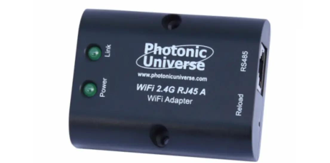
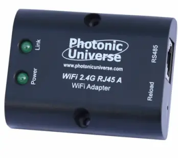
Appearance
WiFi 2.4G RJ45 A
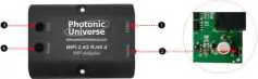
- Interface instruction
No. Name Instruction ❶ RJ45 port Connect to the solar controller, inverter, or inverter/charger ❷ Reload button One key to restoring factory settings Note: Long press the Reload button with a sharp object when the terminal’s power is on. The Link indicator flashes twice quickly, and the factory settings are restored.
❸ Link indicator Indicate the communication status ❹ Power indicator Indicate the power status - Indicator instruction
Indicator Status Instruction Link indicator ON solid in green Connect to the WiFi OFF Not connect to the WiFi Fast flashing in green Reset to the factory mode Power indicator ON solid in green Normal powered on OFF Not powered on
WiFi 2.4G DB9 B
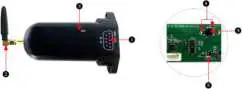
- Interface instruction
No. Name Instruction ❶ DB9 male connector« Connect to the solar controller, inverter, or inverter/charger ❷ Antenna Enhance the signal transmission ❸ Reset button One key to restoring factory settings Note: Long press the Reset button through the KEY hole with a sharp object when the terminal’s power is on. The indicator light flashes twice quickly, and the factory settings are restored.
❹ Network Indicator Indicate the communication status
(Observe the indicator status through the KEY hole)❺ Power Indicator Indicate the power status
Connect the WiFi 2.4G DB9 B to the solar controller, inverter, or inverter/charger by a DB-9 female connector. The wire sequence and name of the DB9 female connector are shown below. 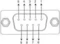
| No. | Name | Instruction | No. | Name | Instruction |
| 1 | NC | Floating | 6 | NC | Floating |
| 2 | NC | Floating | 7 | RS485-A | RS485-A |
| 3 | VCC2 | Power2 (12V/200mA) | 8 | RS485-B | RS485-B |
| 4 | GND2 | Power GND2 | 9 | VCC1 | Power1 (5V/400mA) |
| 5 | GND1 | Power GND1 |
- Indicator instruction
| Indicator | Status | Instruction |
| Network Indicator | ON solid in green | Connect to the WIFI |
| OFF | Not connect to the WIFI | |
| Fast flashing in green | Reset to the factory mode | |
| Power Indicator | ON solid in green | Normal powered on |
| OFF | Not powered on |
Specifications
| Model Parameters | WiFi 2.4G RJ45 A | WiFi 2.4G DB9 B |
| Input voltage | 5VDC | |
| Power consumption | Peak emission: 5V@100mA; Idle: 5V@40mA | |
| Enclosure | IP54 | |
| Communication method | RS485 | |
| Com. parameters | 9600~115200bps, 8N1 | |
| Working Frequency | 2.4~2.4835GHz | |
| Antenna gain | 2.5dBi~ 5dBi | |
| Environment temp. | -40℃~ 85℃ | |
| Com. standard | general communication standardV1-1.0 | |
| Com. protocol | IoT communication protocol V1.1 | |
| Com. port | RJ45 | DB9 |
| Dimension | 66.24* 51.28* 23.76mm | 101.2* 64* 26mm |
| Net weight | 38.5g | 39.5g |
Disclaimers
The warranty does not apply to the following conditions:
- Damage caused by improper use or inappropriate environment.
- The parameter setting exceeds the WiFi terminal’s limit.
- Damage caused by working temperature exceeds the rated range.
- Unauthorized dismantles or attempted repairs.
- Damage caused by force majeure.
- Damage occurred during transportation or handling.
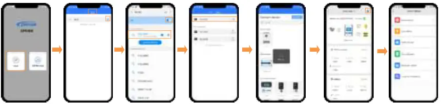
WiFi on Cloud (connect the device to the cloud server)
CAUTION: Please get the Android or IOS version of the cloud APP according to your phone system and install it successfully.
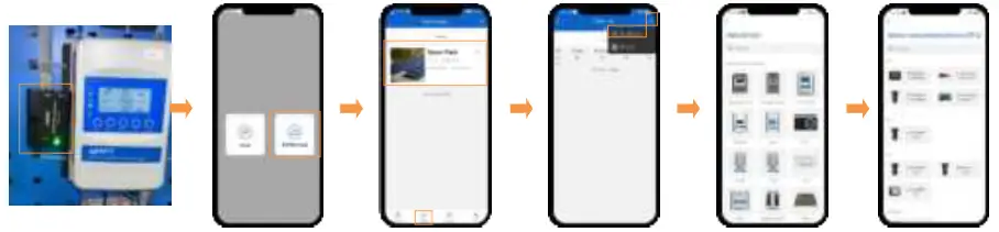
- Step1: Connect the WIFI module to the device (select the connection cable by the COM port).
- Step2: Open the APP, click the “Cloud” icon, and input the account to login.
- Step3: Click the “Plant” icon (it is “Light” icon instead when login with the streetlight account), and select a project.
- Step4: Click “ > Add Device” on the “Plant List” page.
- Step5: Select the device to be added to the cloud server.
- Step6: Select the connected WIFI module.
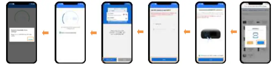
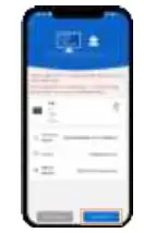
- Step 7: Input the ID (or scan the QR code) on the module label, and click “Confirm.”
- Step 8: This page shows if the module’s IMEI has been recorded in the cloud server, and click “Next.”
- Step 9: Input the router password and click “Next” (Put the router in a 2.4G WiFi area).
- Step 10: Click “Set up Wi-Fi” and connect the phone to “HN_xx”WiFi (see the model’s label for password). Back to the APP, click “Next.”
- Step 11: Enter the WiFi module configuring page. Do not disconnect the network while configuring RTU.
- Step 12: Click “Confirm” to go to the WiFi setting. Connect the phone to the router WiFi again. Return to the APP, the Plant or light project shows.

- (Option) Step 9: Return to the APP, and click “Read device.” Copy the ID and IMEI, then send them to our technical staff. Users can normally add the module after it is recorded in the cloud server.

- (Option) Step 8: Right page shows if the module’s IMEI has not been recorded in the cloud server. Click “Connect RTU” to jump to the WiFi setting, and connect the phone to the “HN_xx” WiFi (see the model’s label for password).

Local Debugging (direct point-to-point communication with the device via WiFi)
Step 1: Connect the WiFi module to the device (connection figure, see Step1 in chapter 5, “WiFi on Cloud”).
- Step 2: Open the APP and click the “Local” icon.
- Step 3: Click the “WiFi” or to go to the phone WiFi setting.
- Step 4: Connect the phone to the “HN_xx”WiFi (see the model’s label for password).
- Step 5: After the WIFI connection, return the APP and click the connected WIFI module.
- Step 6: Auto identify the connected device; you can also select the device manually.
- Step 7: After the device connection, the real-time page shows. Click on the top right crone
- Step 8: Enter the parameter setting page to read and write related parameters.


