![]()
Owner’s Manual & Safety Instructions
Save This Manual Keep this manual for the safety warnings and precautions, assembly, operating, inspection, maintenance, and cleaning procedures. Write the product’s serial number in the back of the manual near the assembly diagram (or month and year of purchase if a product has no number). Keep this manual and the receipt in a safe and dry place for future reference.
CENTRAL PNEUMATIC
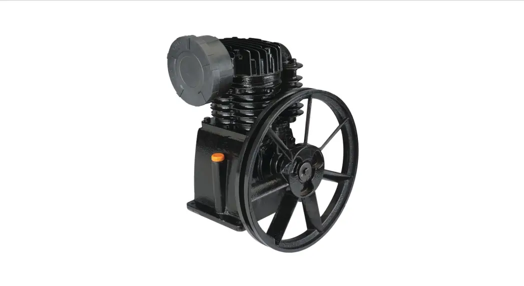
Cast iron
twin cylinder
air compressor
pump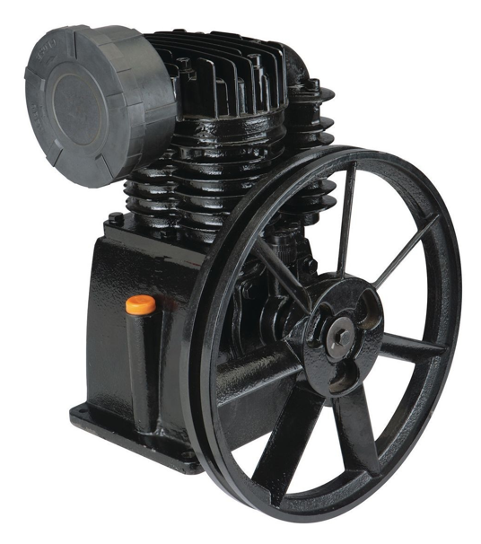
Visit our website at: http://www.harborfreight.com
Email our technical support at: [email protected]
67697
When unpacking, make sure that the product is intact and undamaged. If any parts are missing or broken, please call 1-888-866-5797 as soon as possible. © Copyright
2010 by Harbor Freight Tools ®. All rights reserved.
No portion of this manual or any artwork contained herein may be reproduced in any shape or form without the express written consent of Harbor Freight Tools. Diagrams within this manual may not be drawn proportionally. Due to continuing improvements, the actual product may differ slightly from the product described herein. Tools required for assembly and service may not be included.
 WARNING
Read this material before using this product. Failure to do so can result in serious injury. SAVE THIS MANUAL.
WARNING SyMBOLS AND DEFINITIONS
| This is the safety alert symbol. It is used to alert you to potential personal injury hazards. Obey all safety messages that follow this symbol to avoid possible injury or death. | |
 DANDER DANDER | Indicates a hazardous situation that, if not avoided, will result in death or serious injury. |
| WARNING | Indicates a hazardous situation that, if not avoided, could result in death or serious injury. |
| CAUTION | Indicates a hazardous situation that, if not avoided, could result in minor or moderate injury. |
NOTICE CAUTION | Addresses practices not related to personal injury. |
IMPORTANT SAFETy INFORMATION
General Safety Warnings
| WARNING Read all safety warnings and instructions. Failure to follow the warnings and instructions may result in electric shock, fire, and/or serious injury. Save all warnings and instructions for future reference. |
The warnings, precautions, and instructions discussed in this instruction manual cannot cover all possible conditions and situations that may occur. It must be understood by the operator that common sense and caution are factors that cannot be built into this product but must be supplied by the operator.
1. Work area safety
a. Keep the work area clean and well-lit. Cluttered or dark areas invite accidents.
b. Do not operate the compressor Pump in explosive atmospheres, such as in the presence of flammable liquids, gases or dust. Compressor pump motors produce sparks
which may ignite the dust or fumes.
c. Keep children and bystanders away from an operating compressor pump.
2. Personal safety
a. Stay alert, watch what you are doing, and use common sense when operating this compressor pump. Do not use this compressor pump while you are tired or under the influence of drugs, alcohol, or medication. A moment of inattention while operating a compressor pump may result in serious personal injury.
b. use personal protective equipment. Always wear ANSI-approved eye protection during setup and use.
General Safety Warnings (continued)
3. compressor Pump use and care
a. Disconnect the plug of the compressor motor from the power source before installing, making any adjustments, changing accessories, or storing the compressor Pump. Such preventive safety measures reduce the risk of starting the unit accidentally.
b. Store an idle compressor pump out of the reach of children and do not allow persons unfamiliar with the compressor pump or these instructions to operate it. A compressor pump is dangerous in the hands of untrained users.
c. Maintain the compressor Pump. Keep the compressor Pump clean for better and safer performance. Follow instructions for lubricating and changing accessories. Keep dry, clean and free from oil and grease. check for misalignment or binding of moving parts, breakage of parts and any other condition that may affect the compressor’s operation. If damaged, have the compressor repaired before use. Many accidents are caused by a poorly maintained compressor pump.
d. use the compressor Pump in accordance with these instructions, taking into account the working conditions and the work to be performed. Use of the Compressor Pump for operations different from those intended could result in a hazardous situation.
4. Service
a. Have the compressor Pump serviced by a qualified repair person using only identical replacement parts. This will ensure that the safety of the Compressor Pump is maintained.
compressor Pump Safety Warnings
- Only a qualified engineer with appropriate certifications may attempt designing a new compressor to ensure that all required safety and control elements are in place and will work together properly and safely. This compressor pump is intended ONLy as a replacement for a similarly rated pump on an existing compressor that includes all other needed components. constructing a new compressor using this pump is not covered by this manual.
- use Safety Guard for Pulleys. The Air Compressor Pump Pulley (59), V-belt (not included), and motor pulley (not included) must be covered by a safety guard (not included) covering all moving elements before operation.
- Before first and every use, verify Pump has sufficient oil.
- The use of accessories or attachments not recommended by the manufacturer may result in a risk of injury to persons.
- Misalignment between Motor and Pump can damage the Pump Pulley. Use a straight edge, such as a yardstick, to check and adjust alignment as needed.
- use proper size motor and motor pulley. This Air Compressor Pump must be installed with a 3 HP electric motor and pulley (both not included) which can turn the Air compressor Pump Pulley at approximately 1050 rpm.
- Install motor, pulley belt, and pulley belt cover securely. Be sure to use the proper size bolts to install the motor (not included). The belt and belt cover (not included) must be strong enough to prevent breaking and possible injury.
- Be sure all equipment is rated to the appropriate capacity of this pump. Make sure that the lowest-rated piece of equipment being used can handle the maximum pressure of the Air Compressor Pump (see Specifications).
- Do not direct the airstream at any person or animal.
- Avoid burns. The Cylinder (39), Cylinder Head (3) and Air Outlet components become very hot during operation. Do not touch.
- Industrial applications must follow OSHA guidelines.
- Maintain labels and nameplates on the Compressor Pump. These carry important safety information. If unreadable or missing, contact Harbor Freight Tools for a replacement.
- This product is not a toy. Keep it out of reach of children.
Air compressor Safety Warnings
- Risk of fire or explosion – do not spray flammable liquid in a confined area or towards a hot surface. The spray area must be well-ventilated. Do not smoke while spraying or spray where spark or flame is present. Arcing parts – keep compressor at least 20 feet away from explosive vapors, such as when spraying with a spray gun.
- Risk of bursting – do not adjust regulator higher than the marked maximum pressure of attachment.
- Risk of injury – do not direct airstream at people or animals.
- Do not use to supply breathing air.
- Do not leave the compressor unattended for an extended period while plugged in. unplug the compressor after working.
- Keep compressor well-ventilated. Do not cover the compressor during use.
- Drain tank daily and after use. Internal rust causes tank failure and explosion.
- Add the correct amount of compressor oil before first use and every use. Operating with low or no oil causes permanent damage and voids the warranty.
- Do not remove the valve cover or adjust internal components.
- The compressor head gets hot during operation. Do not touch it or allow children nearby during or immediately the following operation.
- Do not use the air hose to move the compressor.
- Release the pressure in the storage tank before moving.
- The use of accessories or attachments not recommended by the manufacturer may result in a risk of injury to persons.
- All airline components, including hoses, pipes, connectors, filters, etc., must be rated for a minimum working pressure of 150 PSI, or 150% of the maximum system pressure, whichever is greater.
- USE OF AN EXTENSION CORD IS NOT RECOMMENDED. If you choose to use an extension cord, use the following guidelines:
| TABLE A: RECOMMENDED MINIMUM WIRE GAUGE FOR EXTENSION CORDS (120 VOLT) | ||||
| NAMEPLATE AMPERES (at full load) | EXTENSION CORD LENGTH | |||
| 25′ | 50′ | 100′ | 150′ | |
| 0 – 6 | 18 | 16 | 16 | 14 |
| 6/1/10 | 18 | 16 | Do not use. | |
| 10/1/12 | 16 | 16 | Do not use. | |
| 12/1/16 | 14 | 12 | Do not use. | |
a. Make sure your extension cord is in good condition.
b. Be sure to use an extension cord that is heavy enough to carry the current your product will draw. An undersized cord will cause a drop in line voltage resulting in loss of power and overheating. Table A shows the correct size to use depending on cord length and nameplate ampere rating. If in doubt, use the next heavier gauge. The smaller
the gauge number, the heavier the cord.
16. Operate unit on a level surface. Check oil level daily and fill to marked level if needed.
17. People with pacemakers should consult their physician(s) before use. Electromagnetic fields in close proximity to the heart pacemakers could cause pacemaker interference or pacemaker failure.
![]() SAVE THESE INSTRucTIONS.
SAVE THESE INSTRucTIONS.
GROUNDING
WARNING
 | TO PREVENT ELEcTRIc SHOcK AND DEATH FROM INcORREcT GROuNDING WIRE cONNEcTION: check with a qualified electrician if you are in doubt as to whether the outlet is properly grounded. Do not modify the power cord plug provided with any motor used with this compressor Pump. Never remove the grounding prong from the plug. Do not use the motor if the power cord or plug is damaged. If damaged, have it repaired by a service facility before use. If the plug will not fit the outlet, have a proper outlet installed by a qualified electrician. |
Symbology
| PSI | Pounds per square inch of pressure |
| CFM | Cubic Feet per Minute flow |
| SCFM | Cubic Feet per Minute flow at standard conditions |
| NPT | National pipe thread, tapered |
| NPS | National pipe thread, straight |
| Double Insulated | |
| V | Volts |
| Alternating Current | |
| A | Amperes |
SPECIFICATIONS
| Type | Single Stage Twin Cylinder; Oil Lubricated |
| Required HP | 3 HP motor |
| Rated Air Pressure | 145 PSI |
| Maximum Speed | 1050 RPM |
| Air Outlet | 3/4″-16 UNF |
| Air Delivery @ 1050 RPM | 11 SCFM @ 40 PSI 10 SCFM @ 90 PSI |
| Lubrication | Splash Type with Oil Level Window |
| Oil Type | SAE 30W non-detergent Air Compressor Oil (Sold separately) |
| Pump Pulley | 12-1/2″ diameter with single V-groove |
| Belt Type | 1397 |
| Mounting Hole Pattern | 5-23/32″ x 7-5/16″ (center-to-center) Four 3/8″ diameter holes |
| Recommended Mounting Bolts | 5/16″ diameter, grade 5 or better |
| Overall Dimensions | 12-5/8″ L x 10-3/4″ W x 14-1/4″ H |
| Sound Level | 89 dB @ 1m |
INSTRUCTIONS FOR PUTTING INTO USE
Read the ENTIRE IMPORTANT SAFETy INFORMATION section at the beginning of this manual including all text under subheadings therein before set up or use of this product.
WARNING
PREVENT SERIOuS INJuRy FROM AccIDENTAL OPERATION: Turn the power switch “OFF” and unplug the motor from its electrical outlet before
assembling or making any adjustments to the compressor Pump.
WARNING
| TO PREVENT SERIOuS INJuRy AND DEATH FROM IMPROPER INSTALLATION: Only a qualified engineer with appropriate certifications may attempt designing a new compressor to ensure that all required safety and control elements are in place and will work together properly and safely. This compressor pump is intended ONLy as a replacement for a similarly rated pump on an existing compressor that includes all other needed components. constructing a new compressor using this pump is not covered by this manual. |
Note: For additional information regarding the parts listed in the following pages, refer to the Assembly Diagram near the end of this manual.
components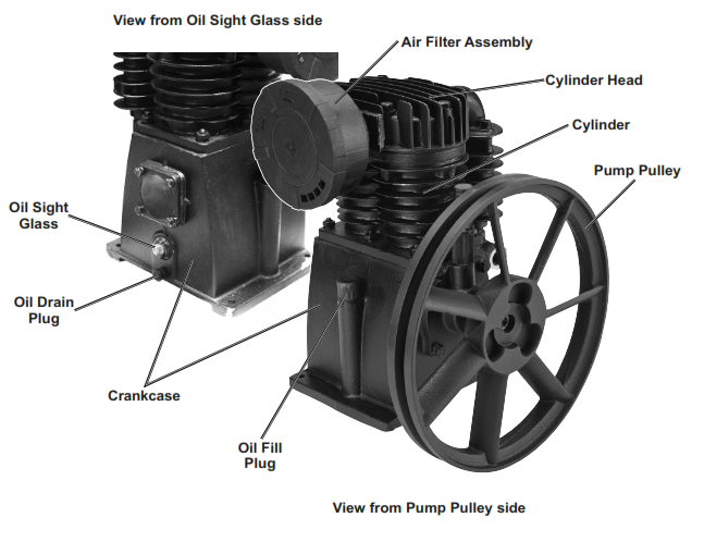
Assembly
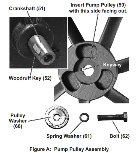
- Place a small amount of grease in the slot at the tapered end of the Crankshaft (51) and insert the Woodruff Key (52) into the slot.
- Make sure that the center hole and the keyway on the Pump Pulley (59) are clean and free of burrs and rough edges.
- Apply a thin layer of grease to the hole and keyway. With the indented side of the Pulley center facing out, align the keyway with the Woodruff Key and slide the Pump Pulley over the Crankshaft.
WARNING! Do not force or hammer the Pump Pulley onto the crankshaft. - Slide the Pulley Washer (60) and Spring Washer (61) onto the Bolt (62) and insert the Bolt through Pump Pulley and thread counterclockwise into the Crankshaft. Tighten using a wrench (not included).
Note: The Bolt has a left-hand thread. To tighten, turn Bolt counterclockwise.
Installation
Note: Depending on your level of expertise, you may wish to have a qualified technician perform this installation.
CAUTION! Avoid damage to the Air Compressor Pump and other equipment. The Compressor Pump mounting platform should be flat, level, and strong enough to support the combined weight of the Pump, electric motor or engine, and related hardware and equipment. It must also be capable of withstanding the vibration and tension of the drive belt.
- Place the Air Compressor Pump on the mounting surface at the same level as the 3 HP motor used to drive it. Pump positioning must incorporate easy access to the Oil rain Plug (48).
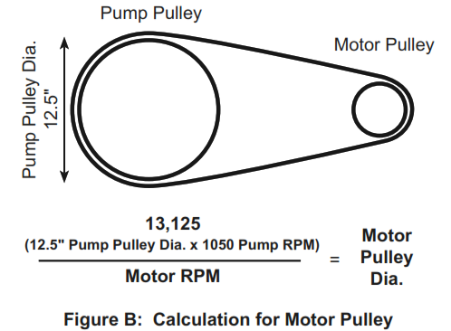
- Use a motor with the appropriate size pulley to achieve the needed Pump RPM. To calculate the motor and motor pulley needed to power the pump, multiply the Pump Pulley diameter (12.5″) times the pump working RPM (1050) which equals 13,125, then divide by the motor RPM. This will determine the motor pulley diameter (in inches) needed to run the unit. For example: To calculate the pulley diameter needed for a 1725 RPM motor, multiply 12.5 by 1050, then divide by 1725, which equals a motor pulley size of 7.6 inches. Use the pulley size closest to this figure.
13,125 = 7.6″
1725
- The Pump Pulley (59) must be in perfect alignment with the motor pulley (not included). Misalignment between the Motor and the Pump can cause damage to both the motor and the compressor pump. Use a straight edge, such as a yardstick, to check and adjust alignment as needed.
Note: Ensure the Pump Pulley is installed for counterclockwise rotation when facing the pulley side of the Pump. - Verify that the Pump Pulley turns freely where it overhangs the mounting surface.
- Place a V-groove belt (not included) over the Pump Pulley and the motor pulley.
Installation (continued) - Pull the Compressor Pump until properly aligned, and the belt is tight. Recheck the motor pulley, V-belt, and Pump Pulley alignment.
- Use mounting holes in the Compressor Pump base as a template to mark the spots where four holes will be drilled in the mounting surface.
- Move the Compressor Pump aside and drill four 5/16″ diameter holes in the mounting surface.
- Move the Compressor Pump back to its mounting position and secure each corner of the base with a 5/16″ diameter grade 5 or better bolt, washer, lock washer, and nut all not included).
- Make final alignment and adjust belt tension with the motor. It may be necessary to loosen the motor mounting bolts to adjust the motor location. To test the proper tension n the V-belt, press down on the belt — there should be 1/2″ deflection or less at mid-span. Tighten all mounting hardware.
- Connect plumbing hardware (not included) from the male 3/4″ Air Outlet (15) to the air destination (i.e., air pressure tank of the compressor, not included), routing the tubing in the shortest possible path.
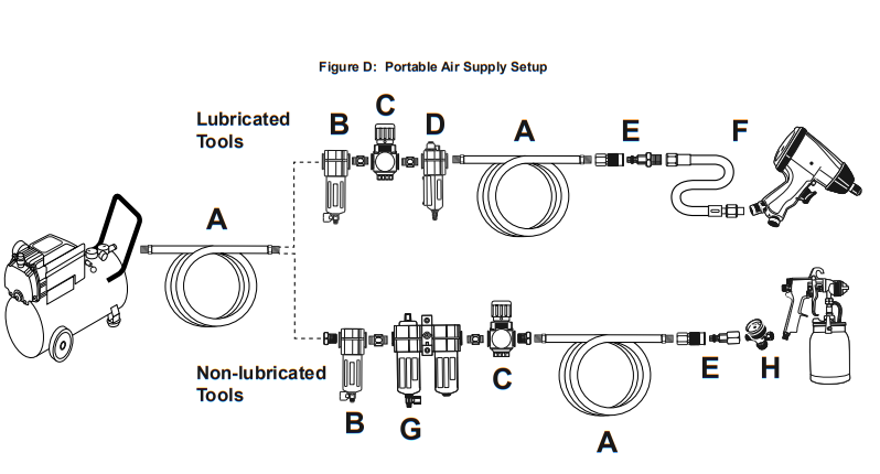
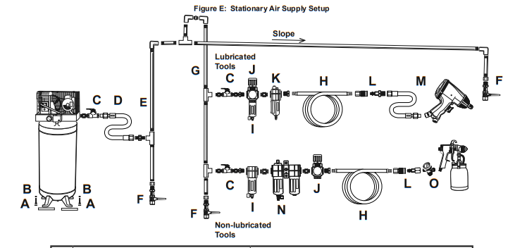
- Depending on the tool which you will be using with this Compressor Pump, you may need to incorporate additional components, such as an in-line oiler, a filter, or a dryer (all sold separately), as shown on Figure D on page 9 and Figure E on page 10. Consult your air tool’s manual for needed accessories.
- Install a safety guard (not included) that surrounds the motor pulley, V-belt, and Pump Pulley. This safety guard must cover all sides of the moving belt and pulleys. It should have a clearance of about one inch from the moving parts. The safety guard must be sturdy enough to prevent injury.
WARNING! Avoid serious injuries. Do not operate this Air compressor Pump without a safety guard in place. - To operate, fill the Compressor Pump Crankcase with Air Compressor Oil (sold separately) following the directions in the next section. Then follow the manufacturer’s operating instructions and safety warnings applicable to your air compressor.
checking the Oil
- Check the oil level before operation. Fill the Pump Crankcase with SAE 30W, non-detergent, Air Compressor Oil (sold separately).
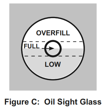
IMPORTANT: Running the Air compressor Pump with no oil or low oil will cause damage to the equipment and void the warranty. - The oil level should be at the center of the FULL level on the oil level sight glass, as shown in Figure C. Add oil as needed to maintain this level. Do not let the oil level go below the center dot (LOW as shown in Figure C) and do not overfill the oil so that it is above the center dot (OVERFILL as shown in Figure C) on the sight glass.

- To add oil: a. Remove the Oil Fill Plug. b. Using a funnel to avoid spills, pour enough oil into the Pump Crankcase to reach the FULL level in the Oil Sight Glass. c. Replace the Oil Fill Plug.
Note: SAE 30W, non-detergent, Air Compressor Oil (sold separately) is recommended for use with this compressor. - If uncertain which oil to use for this compressor, call Harbor Freight Tools customer service at 1-800-444-3353 for assistance.
- change the compressor oil after the first hour of use to remove any debris.
CAUTION! TO PREVENT INJURy FROM BURNS: Do not add or change the oil while the compressor is in operation. Allow the compressor to cool before replacing oil. Note: This pump will consume oil during operation, so check oil level before every use.
| Description | Function | |
| A | Air Hose | Connects air to tool |
| B | Filter | Prevents dirt and condensation from damaging tool or workpiece |
| C | Regulator | Adjusts air pressure to tool |
| D | Lubricator (optional) | For air tool lubrication |
| E | Coupler and Plug | Provides quick connection and release |
| F | Leader Hose (optional) | Increases coupler life |
| G | Air Cleaner / Dryer (optional) | Prevents water vapor from damaging the workpiece |
| H | Air Adjusting Valve (optional) | For fine-tuning airflow at the tool |
| Description | Function | |
| A | vibration Pads | For noise and vibration reduction |
| B | Anchor Bolts | Secures air compressor in place |
| C | Ball Valve | Isolates sections of the system for maintenance |
| D | Isolation Hose | For vibration reduction |
| E | Main Air Line – 3/4″ minimum recommended | Distributes air to branch lines |
| F | Ball Valve | To drain moisture from the system |
| G | Branch Air Line -1/2″ minimum recommended | Brings air to point of use |
| H | Air Hose | Connects air to the tool |
| I | Filter | Prevents dirt and condensation from damaging tool or workpiece |
| J | Regulator | Adjusts air pressure to the tool |
| K | Lubricator (optional) | For air tool lubrication |
| L | Coupler and Plug | Provides quick connection and release |
| M | Leader Hose (optional) | Increases coupler life |
| N | Air Cleaner / Dryer (optional) | Prevents water vapor from damaging the workpiece |
| O | Air Adjusting Valve (optional) | For fine-tuning airflow at the tool |
MAINTENANCE AND SERVICING
Procedures are not specifically explained in this manual must be performed only by a qualified technician.
WARNING
TO PREVENT SERIOuS INJuRy FROM AccIDENTAL OPERATION: Turn the power switch “OFF” and unplug the motor from its electrical outlet before
performing any inspection, maintenance, or cleaning procedures. TO PREVENT SERIOuS INJuRy FROM cOMPRESSOR FAILuRE: Do not use damaged equipment. If abnormal noise or vibration occurs, have the problem corrected before further use.
cleaning, Maintenance, and Lubrication
1. BEFORE EAcH used, inspect the general condition of the Compressor Pump. Check for:
- low oil level
- loose hardware
- misalignment or binding of moving parts
- worn, cracked, or damaged belts
- cracked or broken parts
- any other condition that may affect its safe operation.
2. AFTER USE, wipe the external surfaces of the compressor with a clean cloth.
Maintenance Schedule
Following are general guidelines for maintenance checks of the Air Compressor Pump.
Note The environment in which the Compressor Pump is used, and the frequency of use can affect how often you will need to check the pump components and perform maintenance procedures.
Daily:
a. Check oil level.
b. Check for oil leaks.
c. Make sure all nuts and bolts are tight.
d. Check for abnormal noise or vibration.
e. Check for air leaks.
f. Inspect belt.
g. Wipe off any oil or dirt from the Compressor Pump.
Weekly:
a. Inspect Air Filter.
b. Inspect Oil Breather Plug.
Monthly:
Check belt adjustment.
Every 6 months or 100 Operation Hours: Replace Pump oil. ***
* To check for air leaks, apply soapy water to joints while the Air Compressor is pressurized. Look for air bubbles.
** To clean the compressor pump surface, wipe with a damp cloth, using a mild detergent or mild solvent. The compressor is pressurized. Look for air bubbles.
** To clean the compressor pump surface, wipe with a damp cloth, using a mild detergent or mild solvent.
*** Use SAE 30W, non-detergent, Air Compressor Oil only (sold separately).
Oil Maintenance
Check the oil periodically for clarity. Replace oil if it appears milky or if debris is present, or every 6 months, or 100 hours of runtime, whichever comes first. In harsh environments such as high heat or high humidity, you will need to replace the oil more frequently.
CAUTION! TO PREVENT INJURY FROM BURNS: Allow compressor Pump to cool before changing the oil.
- Place a container under the Oil Drain Plug.
- Remove the Oil Fill Plug to allow airflow into the Pump.
- Remove the Oil Drain Plug, allowing the oil to drain into the container.
- When the oil is completely drained from the pump, replace the Oil Drain Plug.
- Fill the Pump with new SAE 30W, non-detergent, Air Compressor Oil to the FULL level on the Oil Sight Glass.
- Replace and tighten the Oil Fill Plug.
- Discard the old oil according to local, state, and federal regulations.
Air Filter Maintenance
Check the Air Filter weekly to see if it needs replacement.
If working in dirty environments, you may need to replace the filter more often.
- Remove the Air Filter Front Cover.
- Remove the Air Filter element.
- Replace with a new Air Filter element.
- Replace the Cover.
Troubleshooting
| Problem | Possible Causes | Likely Solutions |
| Compressor builds pressure too slowly | 1. Crankcase oil overfilled or oil too thick. 2 Working environment too cold. 3. Loose fittings. | 1. Drain oil and refill to the proper level with recommended oil. 2. Move the compressor to a warmer location. Check that recommended oil is in the crankcase. 3. Reduce air pressure, then check all fittings with a soap solution for air leaks and tighten as needed. Do not overtighten. |
| Compressor not building enough air pressure | 1. Air filters need cleaning/replacing. 2. Compressor not large enough for the job. 3. Loose fittings. 4. Hose or hose connections too narrow. 5. Crankcase oil is too thick. 6. High altitude reducing air output. | 1. Check inlet and outlet filters. Clean and/or replace as needed. 2. Check if accessory CFM is met by Compressor. If the Compressor cannot supply enough airflow (CFM), you need a larger Compressor. 3. Reduce air pressure, then check all fittings with a soap solution for air leaks and tighten them as needed. Do not overtighten. 4. Replace with wider hose and/or hose connections. 5. Drain oil and refill to the proper level with recommended oil. 6. Higher altitudes require compressors with greater output. |
| Overheating | 1. Air filters need cleaning/replacing. 2. Crankcase oil is too thin or an incorrect type. 3. Crankcase oil level too low. 4. Unusually dusty environment. 5. Unit not on a level surface. | 1. Check inlet and outlet filters. Clean and/or replace as needed. 2. Drain oil and refill to the proper level with recommended oil. 3. Add oil to the proper level, check for leaks. 4. Clean and/or replace filters more often or move the unit to a cleaner environment. 5. Reposition unit on a level surface. |
|
Excessive noise | 1. Loose fittings. 2. Loose or damaged belt guard. 3. Crankcase overfilled with oil or oil is incorrect thickness or type. 4. Crankcase oil level too low. 5. Unit not on a level surface. | 1. Reduce air pressure, then check all fittings with a soap solution for air leaks and tighten them as needed. Do not overtighten. 2. Replace belt guard. 3. Drain oil and refill to the proper level with recommended oil. 4. Add oil to the proper level, check for leaks. 5. Reposition unit on a level surface. |
| Moisture in the discharge air | Too much moisture in the air. | Install an inline air filter/dryer, and/or relocate to a less humid environment. |
| Air leaks from pump or fittings | Loose fittings. | Reduce air pressure, then check all fittings with a soap solution for air leaks and tighten as needed. Do not overtighten. |
| Oil in discharge air or high oil consumption | 1. Crankcase oil too thin or crankcase overfilled with oil. 2. Unit not on a level surface. 3. Crankcase vent clogged. | 1. Drain oil and refill to the proper level with recommended oil. 2. Reposition unit on a level surface. 3. Clean the Crankcase vent. |
| Follow all safety precautions whenever diagnosing or servicing the compressorDisconnect power supply before service. |
PARTS LIST AND DIAGRAM
PLEASE READ THE FOLLOWING CAREFULLY
THE MANUFACTURER AND/OR DISTRIBUTOR HAS PROVIDED THE PARTS LIST AND ASSEMBLY DIAGRAM THIS MANUAL IS A REFERENCE TOOL ONLY. NEITHER THE MANUFACTURER NOR DISTRIBUTOR MAKES ANY REPRESENTATION OR WARRANTY OF ANY KIND TO THE BUYER THAT HE OR SHE IS QUALIFIED TO MAKE ANY REPAIRS TO THE PRODUCT, OR THAT HE OR SHE IS QUALIFIED TO REPLACE ANY PARTS OF THE PRODUCT. IN FACT, THE MANUFACTURER AND/OR DISTRIBUTOR EXPRESSLY STATES THAT ALL REPAIRS AND PARTS REPLACEMENTS SHOULD BE UNDERTAKEN BY CERTIFIED AND LICENSED TECHNICIANS, AND NOT BY THE BUYER. THE BUYER ASSUMES ALL RISK AND LIABILITY ARISING OUT OF HIS OR HER REPAIRS TO THE ORIGINAL PRODUCT OR REPLACEMENT PARTS THERETO OR ARISING OUT OF HIS OR HER INSTALLATION OF REPLACEMENT PARTS THERETO.
Parts List
| Part | Description | Qty |
| 1 | Bolt | 6 |
| 2 | Spring Washer | 6 |
| 3 | Cylinder Head | 1 |
| 4 | Air Filter Assembly | 1 |
| 5 | Air Filter Front Cover | 1 |
| 6 | Air Filter Element | 1 |
| 7 | Air Filter Rear Cover | 1 |
| 8 | Exhaust Elbow Gasket | 1 |
| 9 | Exhaust Elbow | 1 |
| 10 | Hex Bolt | 4 |
| 11 | Copper Washer | 4 |
| 12 | Exhaust Elbow Gasket | 1 |
| 13 | Exhaust Cooler | 1 |
| 14 | nut | 1 |
| 14a | Air Outlet Ring | 1 |
| 15 | Air Outlet | 1 |
| 16 | Cylinder Head Gasket | 1 |
| 17 | Screw M4 x 10 | 8 |
| 18 | Spring Washer | 8 |
| 19 | Outlet Valve Guard | 2 |
| 20 | Valve Plate | 2 |
| 21 | Valve Seat | 1 |
| 22 | Valve Plate | 2 |
| 23 | Cylinder Gasket | 1 |
| 24 | Piston Ring Set | 2 |
| 25 | Compression Ring | 4 |
| 26 | Oil Ring | 2 |
| 27 | Piston | 2 |
| 28 | Piston Pin | 2 |
| 29 | Piston Pin Clip | 4 |
| 30 | Hex Bolt | 4 |
| 31 | Spring Washer | 4 |
| 32 | Connecting Rod | 2 |
| 33 | Splasher | 2 |
| 34 | Spring Washer | 2 |
| 35 | Screw | 2 |
| 36 | Nut | 6 |
| 37 | Spring Washer | 6 |
| 38 | Stud | 6 |
| 39 | Cylinder | 1 |
| 40 | Cylinder Gasket | 1 |
| 41 | Breather Assembly | 1 |
| 41a | Breather | 1 |
| 41b | Washer | 2 |
| 41c | Ball | 1 |
| 41d | Breather Rod | 1 |
| 42 | Bearing Cover Gasket | 1 |
| 43 | Bearing Cover | 1 |
| 44 | Spring Washer | 4 |
| 45 | Bolt | 4 |
| 46 | Oil Sight Glass | 1 |
| 47 | Washer | 1 |
| 48 | Oil Drain Plug | 1 |
| 49 | Crankcase | 1 |
| 50 | Bearing | 1 |
| 51 | Crankshaft | 1 |
| 52 | Woodruff Key | 1 |
| 53 | Bearing | 1 |
| 54 | Bearing Seat Gasket | 1 |
| 55 | Oil Seal | 1 |
| 56 | Bearing Seat | 1 |
| 57 | Spring Washer | 4 |
| 58 | Bolt 8.8 | 4 |
| 59 | Pump Pulley | 1 |
| 60 | Pulley Washer | 1 |
| 61 | Spring Washer | 1 |
| 62 | Bolt | 1 |
| 63 | Oil Fill Plug | 1 |
| 63a | Washer | 1 |
Record Product’s Serial Number Here:
Note: If the product has no serial number, record the month and year of purchase instead.
Note: Some parts are listed and shown for illustration purposes only, and are not available individually as replacement parts. Specify UPC 792363676977 when ordering parts.
Assembly Diagram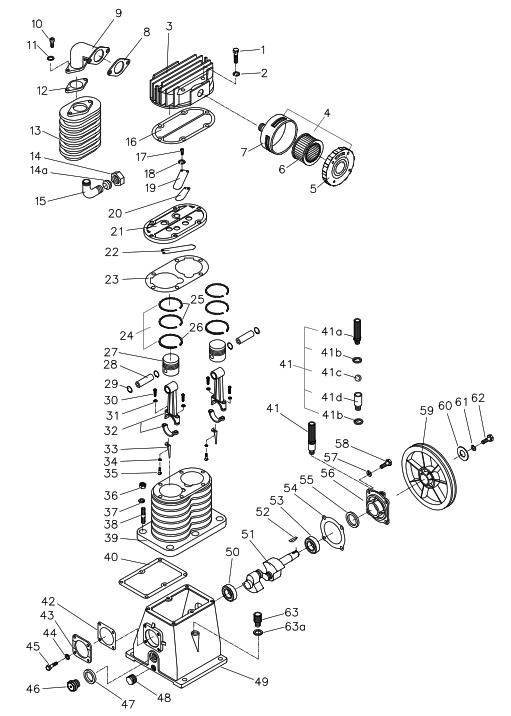
LIMITED 90 DAY WARRANTY
Harbor Freight Tools Co. makes every effort to assure that its products meet high quality and durability standards, and warrants to the original purchaser that this product is free from defects in materials and workmanship for the period of 90 days from the date of purchase. This warranty does not apply to damage due directly or indirectly, to misuse, abuse, negligence or accidents, repairs or alterations outside our facilities, criminal activity, improper installation, normal wear, and tear, or to lack of maintenance. We shall in no vent be liable for death, injuries to persons or property, or for incidental, contingent, special or consequential damages arising from the use of our product. Some states do not allow the exclusion or limitation of incidental or consequential damages, so the above limitation of exclusion may not apply to you. THIS WARRANTY IS EXPRESSLY IN LIEU OF ALL OTHER WARRANTIES, EXPRESS OR IMPLIED, INCLUDING THE WARRANTIES OF MERCHANTABILITY AND FITNESS. To take advantage of this warranty, the product or part must be returned to us with transportation charges prepaid. Proof of purchase date and an explanation of the complaint must accompany the merchandise. If our inspection verifies the defect, we will either repair or replace the product at our election or we may elect to refund the purchase price if we cannot readily and quickly provide you with a replacement. We will return repaired products at our expense, but if we determine there is no defect, or that the defect resulted from causes not within the scope of our warranty, then you must bear the cost of returning the product. This warranty gives you specific legal rights and you may also have other rights which vary from state to state.
![]()
26541 Agoura Road • calabasas, cA 91302 • 1-888-866-5797
For technical questions, please call 1-888-866-5797.
Documents / Resources
 | CENTRAL PNEUMATIC 67697 Cast Iron Twin Cylinder Air Compressor Pump [pdf] Owner's Manual 67697, Cast Iron Twin Cylinder Air Compressor Pump |


