![]()
| Step | Figure | Remark |
| S1. Remove the STAND BASE ASS’Y. | 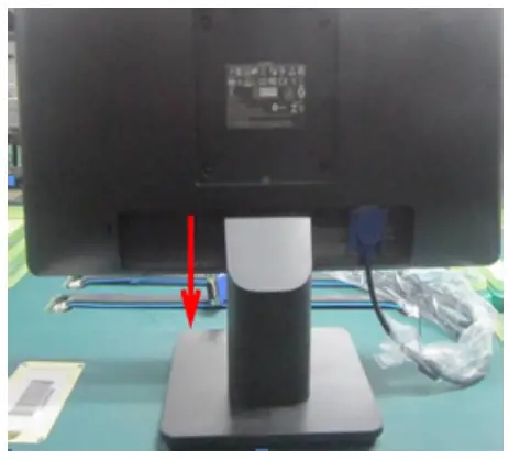 | Turn off power, Unplug external cables from product |
| S1. Remove the STAND BASE ASS’Y. | 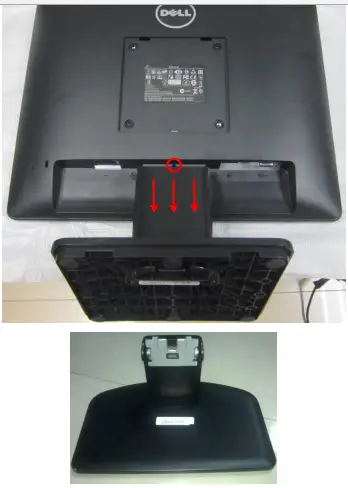 | Note: Put the monitor on a flat, soft and clean surface. Press the button on the red circle then pull out the stand follow the arrow, stand-base assy will be remove. |
| S2. Remove the REAR COVER. | 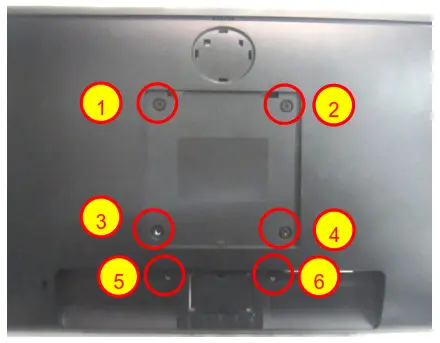 | Use a Philips-head screwdriver to remove 6 screws for unlocking mechanisms. (No.1~2 screw size=M4x10; Torque=12±2kgf.cmNo.5~6 screw size=P3x4; Torque=6±1kgf.cm) |
| S2. Remove the REAR COVER. | 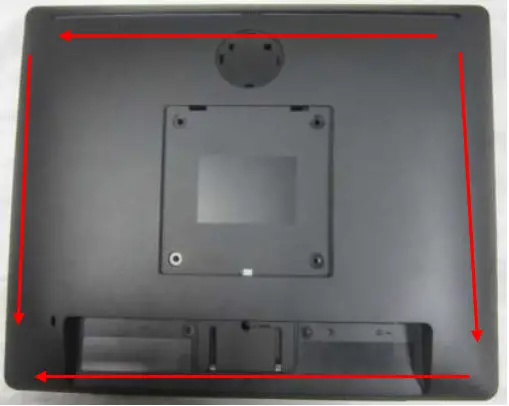 | Use Penknife to separate the bezel and rear cove follow the arrows in sequence, then you can take out rear cover. |
| S3. Remove the Cable. | 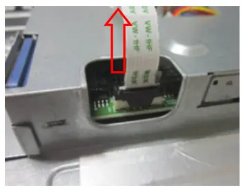
| Disconnect the keyboard harness. |
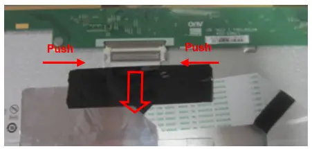
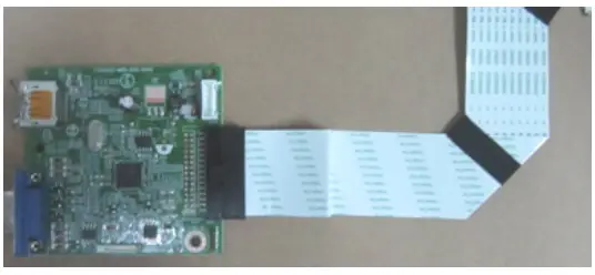
| S4. Disconnect the LED HARNESS and FFC CABLE. | 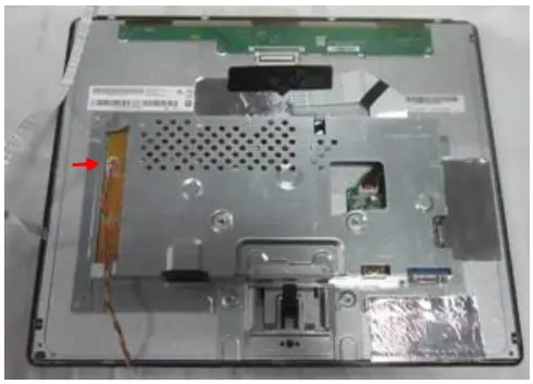
| |
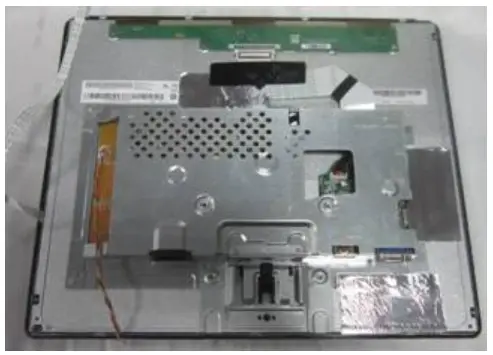
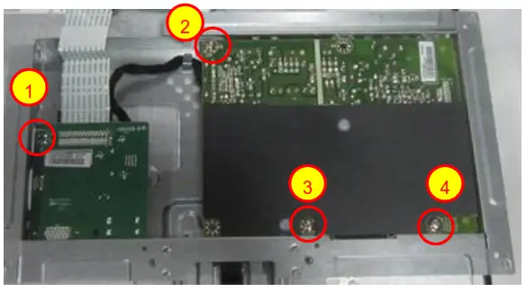
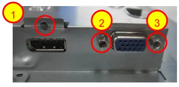
| S5. Remove the MAIN and POWER BOARD. | 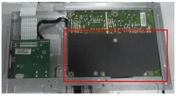
| 1. Turn over the main frame. 2. Remove the Insulatingsheet. Use a Philips-head screwdriver to removescrews for unlocking Mainboard and Power board (No.1~3 screw size=M3x6; Torque=6±1kgf.cm No.4 screw size=M4x6; Torque=6±1kgf.cm) Use a Philips-head screwdriver to remove 1 screws for unlocking Main board (No.1 screw size=M3x5; Torque=6±1kgf.cm)Use a hex screwdriver to remove 2 screws for unlocking mainboard (No.2~3 Hex screw Torque= 4.5 ±0.5kgf.cm) |
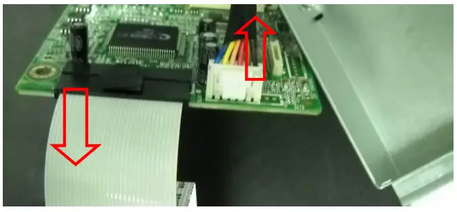
| S6. Disconnect the HARNESS. |
| |
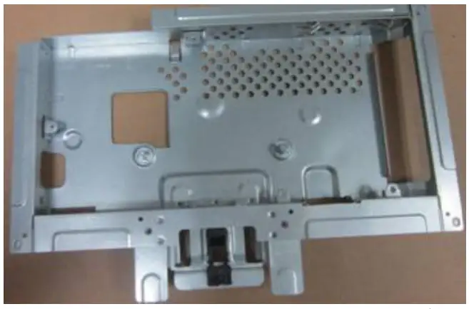
| S7. Remove the MAIN FRAME |
| |
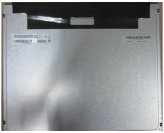
| S8. Remove the PANELfrom Bezel |
| |
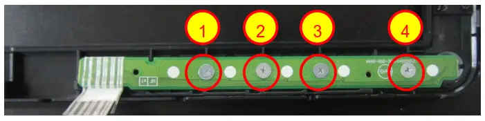
| S9. Remove the KEY BOARD. | 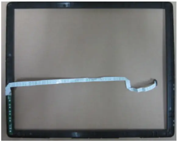
| Use a Philips-head screwdriver to remove 4 screws for unlocking Key board (No.1~4 screw size=M2x2.5; Torque=0.7±0.2kgf.cm) |
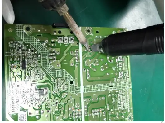
| S10.Remove capacitors | 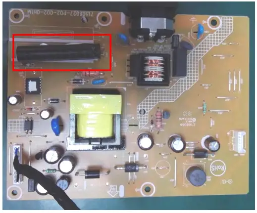 | Remove electrolyte capacitors (red mark) from printed circuit boards |
| S10.Remove capacitors |
| Take out the bulk cap. pin solder with soldering iron and absorber |
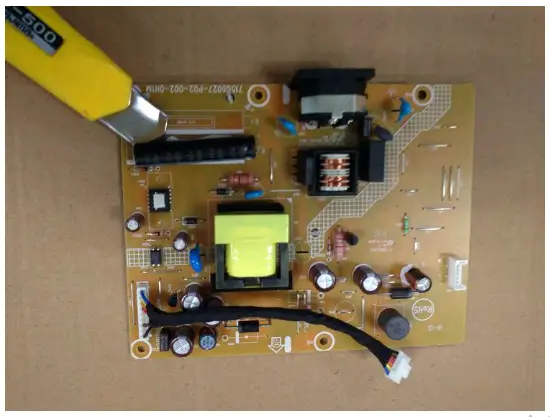 | Lift the bulk cap. up and away from the PCB |
2. Product material information
The following substances, preparations, or components should be disposed of or recovered separately from other WEEE in compliance with Article 4 of EU Council Directive 75/442/EEC.
| Capacitors / condensers (containing PCB/PCT) | No used |
| Mercury-containing components | No used |
| Batteries | No used |
| Printed circuit boards (with a surface greater than 10 square cm) | The product has printed circuit boards (with a surface greater than 10 square cm) |
| The component contains toner, ink, and liquids | No used |
| Plastic containing BFR | No used |
| Component and waste contain asbestos | No used |
| CRT | No used |
| Component contain CFC, HCFC, HFC and HC | No used |
| Gas discharge lamps | No used |
| LCD display > 100 cm2 | The product has an LCD greater than 100 cm2 |
| External electric cable | The product has external cables |
| The component contains refractory ceramic fibers | No used |
| The component contains radioactive substances | No used |
| Electrolyte capacitors (height > 25mm, diameter > 25mm) | Product has electrolyte capacitors (height > 25mm, diameter > 25mm) |
3. Tools Required
List the type and size of the tools that would typically can be used to disassemble the product to a point where components and materials requiring selective treatment can be removed.
Tool Description:
‐ Phillip head Screwdriver
‐ Hex Screwdriver
‐ Penknife
‐ Soldering iron and absorber


