DELL AW3821DWB 38 Inch Curved Gaming Monitor User Guide
Disassembly Procedures
- Turn off power
- Place monitor head on U3818DW curve sponge jig
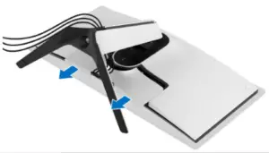
Carefully slide and remove the I/O cover from the monitor.
- Disconnect the cables from the monitor and slide them out through the cable management slot on the stand riser.

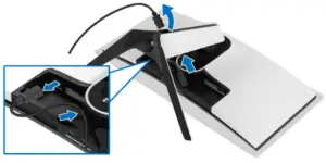
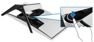
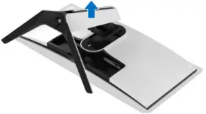
- Press and hold the stand release button

- Lift the stand up and away from the monitor.

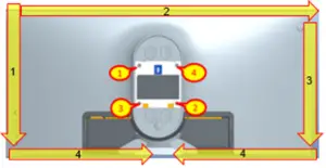
- Unlock 4 screws on rear cover
Use hands or scraper bar to disassemble Rear Cover from the monitor.
Notice the disassembly order:
Left Side=> Top Side=>Right Side=>Bottom Side
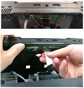
(Screw Torque: 8-10 kgf) - Remove USB FFC and Audio FFC from USB BD

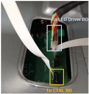
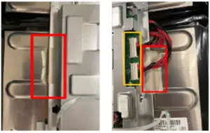
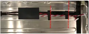
- Remove 1 tape on LED Driver BD wire from Main SHD and disconnect LED Driver BD wire from I/F BD
Disconnect CTRL FFC cable from I/F BD and tear it from Main SHD
Take off Rear Cover
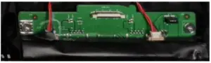
- Remove all tapes from cables and Rear Cover

- Remove all cables from LED Driver BD
Unlock 1 screw and disassemble LED Driver BD from Rear Cover
- Tear off “MYLAR HEAD LOGO” from cover LOGO LENS
Disconnect LED wire from LED BD
Disassemble LED BD from Rear Cover
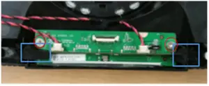
- Tear off RC Mylar from USB BD and Jack BD

- Remove 2 tapes on Jack BD from Rear Cover
Disassemble Jack BD from Rear Cover
Remove 2 wires from Jack BD
Unlock 2 screws to disassemble USB BD from Rear Cover
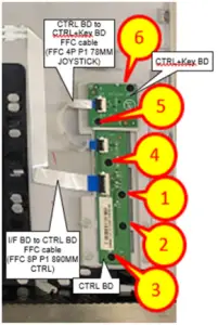
- Remove FFC cable from Rear Cover, CTRL BD and CTRL+KEY BD
Unlock 6 screws to disassemble CTRL BD and CTRL+KEY BD from Rear Cover
- Take off 1 gasket from Middle Frame

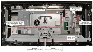
- Disconnect Backlight Wires from SPS+LED BD
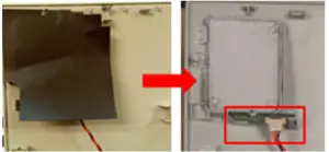
Tear off conductive cloth from Main SHD
- Disconnect Light Sensor BD FFC cable from I/F BD and tear off it from Main SHD
Disconnect Sensor BD FFC cable from I/F BD and tear off it from panel
Disconnect “CTRL+LENS BD FFC” from I/F BD and tear off it from panel and Main SHD
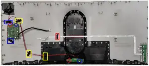
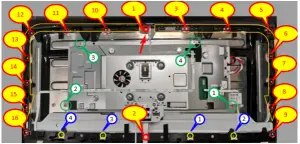
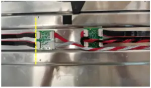
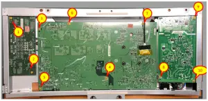
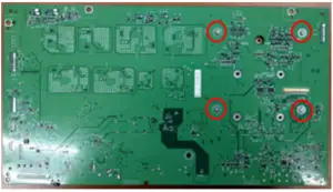
- Unlock 4 screws (Green mark) to disassemble Main SHD from panel
Unlock 16 screws (Red mark) and 4 screws (Yellow mark) to disassemble Middle Frame from Panel
(Screw Torque-Main SHD: 7±1kgf)
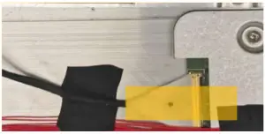
(Screw Torque-Middle Frame: 4.5±0.5 kgf) - Tear off a yellow tape and an acetate tape from EDP cable and panel
Disconnect EDP cable from Panel
Take off Main SHD from Panel
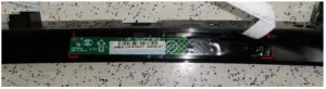
- Tear off a mylar and 2 tapes from Backlight wires

- Disconnect Backlight wires from transfer BD

- Disassemble transfer BD from Panel

- Disassemble Light Sensor BD from Middle Frame

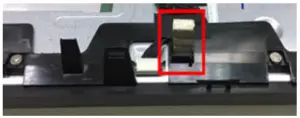
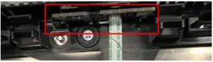
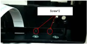
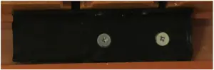
- Unlock 2 screws to disassemble Power Button module from Middle Frame
(Screw Torque: 1.1±0.1 kgf)
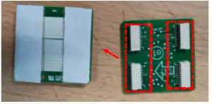
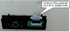
- Disconnect FFC cable from “CTRL+LENS BD” (Power CTRL BD)

- Tear off “MYLAR-PWR-KE “ from “CTRL+LENS BD” (Power CTRL BD)

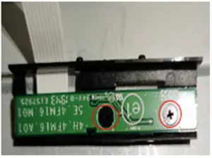
- Unlock 2 screws to disassemble “CTRL+LENS BD” (Power CTRL BD) from Power Button

(Screw Torque: 2±0.5 kgf) - Disassemble Sensor BD from Middle frame

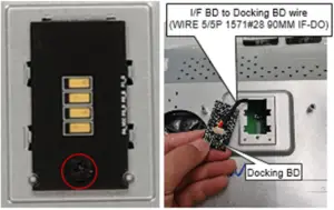
- Unlock 1 screw to disassemble Docking BD from Main SHD
Disassemble wire from Docking BD
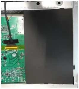
(Screw Torque: 8.5±1.0 kgf) - Disassemble mylar from Main SHD

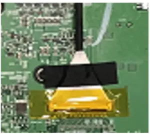
- Tear off an adhesive tape and a yellow tape from I/F BD and EDP cable
Disconnect EDP cable from I/F BD
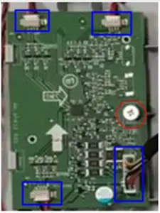
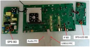
- Unlock 11 screws on PCBA to disassemble SPS+LED BD, SPS BD and I/F BD from Main SHD

(Screw Torque: 8.5±1.0 kgf) - Disconnect wires from I/F BD, SPS BD and SPS+LED BD

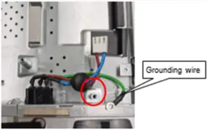
- Unlock 1 ground screw to disassemble AC Socket from Main SHD
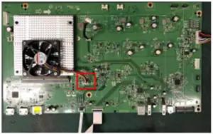
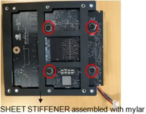
(Screw Torque: 8-10 kgf) - Disconnect Fan Cable from I/F BD

- Unlock 4 screws to disassemble GSYNC Module from I/F BD

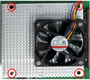
(Screw Torque: 4-4.5 kgf) - Unlock 4 Heat Sink screws and 4 captive screws to disassemble G-Sync module, Heat Sink Module and SHEET STIFFENER
Tear off MYLAR from SHEET STIFFENER
(Screw Torque-Heat Sink: 2-2.5 kgf)
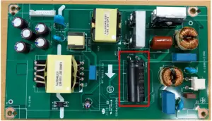
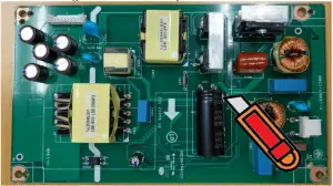
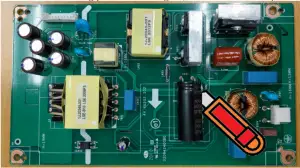
(Screw Torque-Captive screw:4-4.5 kgf) - Remove electrolyte capacitors (red mark) from printed circuit boards

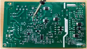
- S38-1 Cut the glue between bulk cap. and PCB with a knife

- S38-2 Ensure cutting path within the glue, don’t touch bulk cap. or PCB
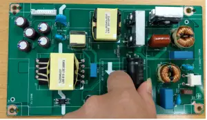
- S38-3 Take out bulk cap. pin solder with soldering iron and absorber
- S38-4 Lift the bulk cap. up and away from the PCB

- Remove electrolyte capacitors (red mark) from printed circuit boards
Product material information
The following substances, preparations, or components should be disposed of or recovered separately from other WEEE in compliance with Article 4 of EU Council Directive 75/442/EEC.
| Capacitors / condensers (containing PCB/PCT) | No used |
| Mercury containing components | No used |
| Batteries | No used |
| Printed circuit boards (with a surface greater than 10 square cm) | Product has printed circuit boards (with a surface greater than 10 square cm) |
| Component contain toner, ink and liquids | No used |
| Plastic containing BFR | No used |
| Component and waste contain asbestos | No used |
| CRT | No used |
| Component contain CFC, HCFC, HFC and HC | No used |
| Gas discharge lamps | No used |
| LCD display > 100 cm2 | Product has an LCD greater than 100 cm2 |
| External electric cable | Product has external cables |
| Component contain refractory ceramic fibers | No used |
| Component contain radio-active substances | No used |
| Electrolyte capacitors (height > 25mm, diameter > 25mm) | Product has electrolyte capacitors (height >25mm, diameter > 25mm) |
Tools Required
List the type and size of the tools that would typically can be used to disassemble the product to a point where components and materials requiring selective treatment can be removed.
Tool Description:
- Screwdriver
- Scraper Bar
- Penknife
- Soldering iron and absorber
- Curve Sponge Jig


