THERMON G-60 Series FLO-DRI Filters Instruction Manual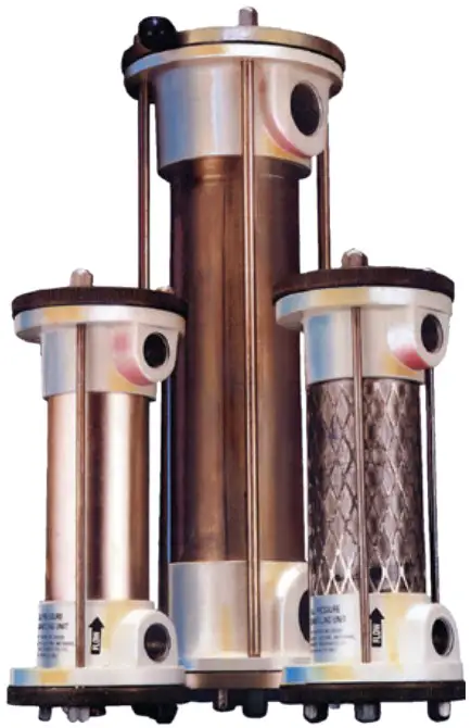
![]() WARNING
WARNING
Improper installation adjustment, alteration, excessive vibration, service, or maintenance can cause property damage, injury or death. Read the installation, operating and maintenance instructions thoroughly before installing, operating or servicing this equipment.
Special Notes
The following special notices highlight important information in the installation, operation and maintenance sections
![]() This symbol indicates a potentially hazardous situation, which, if not avoided, can result in personal injury or damage to the equipment.
This symbol indicates a potentially hazardous situation, which, if not avoided, can result in personal injury or damage to the equipment.
![]() This symbol indicates a potentially hazardous situation, which, if not avoided, may be a shock hazard.
This symbol indicates a potentially hazardous situation, which, if not avoided, may be a shock hazard.
![]() This symbol indicates an imminently hazardous situation, which, if not avoided, could result in death or serious injury
This symbol indicates an imminently hazardous situation, which, if not avoided, could result in death or serious injury
FILTER MAINTENANCE INSTRUCTIONS
- The following simple maintenance procedures will ensure maximum FLO‑DRI filtering efficiency and a longer filter life.
- FLO‑DRI cartridges should be examined frequently until a pattern of usage is established.
- Failure to replace cartridges in an expedient fashion may result in excessive pressure drop and the possibility of contaminant carry over. Refer to the FLO‑DRI Cartridge Change-Out Calculator available on Thermon’s website for recommended change out schedules. This calculator allows the user to determine an accurate cartridge replacement schedule based on their specific application. If the calculator is unavailable, replace cartridges every 30 days or when the cartridge appears to be contaminated.
- Do not subject the unit to vapours or liquids from synthetic solvents, acetone, methanol, esters, lacquer thinners, phosphates, etc.
TO CHANGE FLO‑DRI CARTRIDGES
![]() WARNING.
WARNING.
Never replace filter cartridge when the unit is under pressure. Always follow safe work procedures when working with high pressure.
- Close inlet, wait for unit to vent, then close the outlet isolation valve to the FLO‑DRI filter.
- To vent filter, open drain cock. Make certain filter is COMPLETELY VENTED and under NO pressure prior to removing the top end cap.
- To remove the end cap: depress, turn counter clockwise and pull out. DO NOT LOOSEN CASTLE NUTS.
- Inspect filter media. Replace when completely saturated, or earlier.
 WARNING. Do not reuse contaminated media
 - Insert new FLO‑DRI cartridges (sewn end down) into the filter unit.
- Replace end cap, close drain cock and open isolation valves before returning FLO‑DRI unit to service. Fasten the set-screw ensuring the cap is closed and unable to be removed under pressure. WARNING. It is essential to positively confirm closure of top cap prior to re-pressurizing system.
FILTER INSTALLATION INSTRUCTIONS
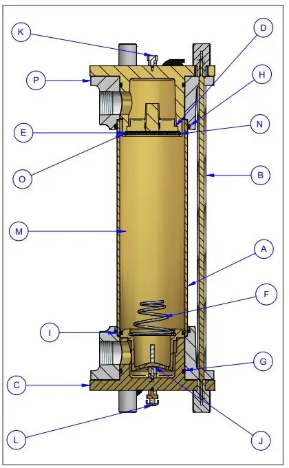
- For maximum efficiency, FLO‑DRI unit should be installed as indicated in
Figure 1 – G-60, G-100, G-150, M-60, M-100 & M-150 Series Assembly Diagram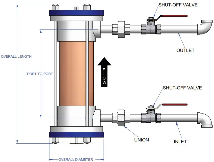
- Install in a vertical position only.
- Tighten fittings into casting 6.0 to 6.5 turns for G-60 and M-60 and 6.5 to 7.0 turns for G-100, G-150, M-100 and M-150. Do not over-tighten threaded connections. This may lead to thread damage or possible cracking of the casting.
- Ensure flow direction is as indicated on the unit.
- Installation of drain leg is highly recommended.
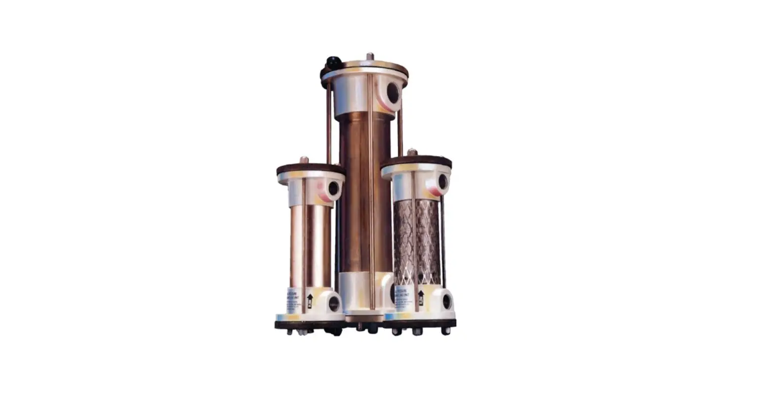
G-60/M-60
G-100/M-100
G-150/M-150
Table 1 – Scrubbing System
| Scrubbing System | Model Number | PSIG | Number of Cartridges | Overall Length | Overall Diameter | Port to Port | Pipe Size NPT | Bed Cubic in7 | Cartridge Media Part No. | |||
| in | mm | in | mm | in | mm | |||||||
| NaturalGas | FLODRI‑G60A | 250 | 3 | 18.25 | 464 | 6.25 | 159 | 12.38 | 314 | 1 | 84.47 | FLODRI‑60AA |
| FLODRI‑60AC | ||||||||||||
| FLODRI‑60MS | ||||||||||||
| FLODRI‑G100A | 4 | 23.31 | 592 | 7.75 | 197 | 17.00 | 432 | 1 1/2 | 199.06 | FLODRI‑100A | ||
| FLODRI‑100AC | ||||||||||||
| FLODRI‑100MS | ||||||||||||
| LODRI‑G150A | 2 | 26.00 | 60 | 9.25 | 41 | 18.19 | 462 | 2 | 376.52 | FLODRI‑150AA | ||
| FLODRI‑150AC | ||||||||||||
| FLODRI‑150MS | ||||||||||||
| Compressed Air | FLODRI‑M60A | 3 | 18.25 | 464 | 6.25 | 159 | 12.38 | 314 | 1 | 84.47 | FLODRI‑60R | |
| FLODRI‑M100A | 4 | 23.31 | 592 | 7.75 | 197 | 17.00 | 432 | 1 1/2 | 199.06 | FLODRI‑100R | ||
| FLODRI‑M150A | 2 | 26.00 | 660 | 9.25 | 241 | 18.19 | 462 | 2 | 376.52 | FLODRI‑150R | ||
CARTRIDGE MEDIA
Natural Gas Cartridge Media
AA – Moisture Removal
AC – Odor Removal
MS – H2S & Moisture Remova
Compressed Air Cartridge Media
R – Moisture, Oil and Heavy Liquids Removal, Air Purifier
To order, specify:
Model number and cartridge media part number.
PARTS LIST
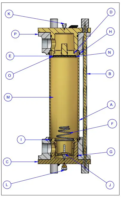
Table 2 – Parts List G-60 & M-60 Series
| Item | No. Req. | Part No. | Description |
| A | 1 | ‑ | Barrel |
| B | 4 | ‑ | Tie rod |
| C | 2 | ‑ | End cap |
| D | 1 | 10262 | Spider, 60 Series |
| E | 1 | 10264 | Screen, 60 Series, 304SS |
| F | 1 | 12090 | Spring, 60 Series, BUNA N70 |
| G | 2 | 10270 | O‑ring, End cap, 60 Series, BUNA N70 |
| H | 2 | ‑ | O‑ring, Body, 60 Series, BUNA N70 |
| I | 1 | 10288 | O‑ring probe 60 Series, BUNA N70 |
| J | 1 | ‑ | Anchor stud, 60 Series |
| K | 1 | ‑ | Plug, 1/8″ Galvanized hex head |
| L | 1 | ‑ | Drain cock, Assembly, 1/8″ NPT |
| M | 3 | ‑ | FLO‑DRI Cartridge |
| N | 1 | 10276 | Membrane, Polyester 60 Series |
| O | 1 | 10266 | Snap ring, 60 Series retainer internal |
| P | 2 | ‑ | Body |
Table 3 – Parts List G-100 & M-100 Series
| Item | No. Req. | Part No. | Description |
| A | 1 | ‑ | Barrel |
| B | 4 | ‑ | Tie rod |
| C | 2 | ‑ | End cap |
| D | 1 | 10303 | Spider, 100 Series |
| E | 1 | 10305 | Screen, 100 Series, 304SS #10 MESH |
| F | 1 | 10307 | Spring, 100 Series |
| G | 2 | 13507 | O‑ring, End cap, 100 Series, BUNA N70 |
| H | 2 | ‑ | O‑ring, Body, 100 Series, BUNA N70 |
| I | 1 | 10311 | O‑ring, Probe, 100 Series, BUNA N70 |
| J | 1 | ‑ | Anchor stud, 100 Series |
| K | 1 | ‑ | Plug, 1/8” Galvanized hex head |
| L | 1 | ‑ | Drain cock, Assembly, 1/8” NPT male |
| M | 4 | ‑ | FLO‑DRI Cartridge |
| N | 1 | 10318 | Membrane, 100 Series |
| O | 1 | 10306 | Snap ring, 100 Series |
| P | 2 | ‑ | Body |
Table 4 – Parts List G-150 & M-150 Series
| Item | No. Req. | Part No. | Description |
| A | 1 | ‑ | Barrel |
| B | 4 | ‑ | Tie rod |
| C | 2 | ‑ | End cap |
| D | 1 | 10324 | Spider, 150 Series |
| E | 1 | 10327 | Screen, 150 Series, 304SS |
| F | 1 | 10330 | Spring, 150 Series bag retainer |
| G | 3 | 10335 | O‑ring, End cap, 150 Series, BUNA N70 |
| H | 2 | ‑ | O‑ring, body, 150 Series, BUNA N70 |
| J | 1 | ‑ | Anchor stud, 150 Series |
| K | 1 | ‑ | Plug, 1/8″ Galvanized hex head |
| L | 1 | ‑ | Drain cock, Assembly, 1/8″ NPT |
| M | 2 | ‑ | FLO‑DRI Cartridge |
| N | 1 | 10342 | Membrane, Polyester 150 Series |
| O | 1 | 10329 | Snap ring, 150 Series, Retainer internal |
| P | 2 | ‑ | Body |
Table 5 – Replacement FLO‑DRI O‑ring 60 Kit
| Item | No. Req. | Part No. | Description |
| G | 2 | 10270 | O‑ring, End cap, 60 Series, BUNA |
| I | 1 | 10288 | O‑ring, Probe, 60 Series, BUNA |
| N | 1 | 10276 | Membrane, 60 Series |
| ‑ | 1 | 10347 | O‑ring lube, 6 Gram packet |
Table 6 – Replacement FLO‑DRI O‑ring 100 Kit
| Item | No. Req. | Part No. | Description |
| G | 2 | 13507 | O‑ring, End cap, 100 Series, BUNA |
| I | 1 | 10311 | O‑ring, Probe, 100 Series, BUNA |
| N | 1 | 10318 | Membrane, 100 Series |
| ‑ | 1 | 10347 | O‑ring lube, 6 Gram packet |
Table 7 – Replacement FLO‑DRI O‑ring 150 Kit
| Item | No. Req. | Part No. | Description |
| G | 3 | 10335 | O‑ring, End cap, 150 Series, BUNA |
| N | 1 | 10342 | Membrane, 150 Series |
| ‑ | 1 | 10347 | O‑ring lube, 6 Gram packet |
For further assistance, please call 24hr hotline: 1‑800‑410‑3131 (U.S.A. and Canada) Please have model and serial numbers available before calling.
WARRANTY: Under normal use the Company warrants to the purchaser that defects in material or workmanship will be repaired or replaced without charge for a period of 18 months from date of shipment, or 12 months from the start date of operation, whichever expires fi rst. Any claim for warranty must be reported to the sales offi ce where the product was purchased for authorized repair or replacement within the terms of this warranty
Subject to State or Provincial law to the contrary, the Company will not be responsible for any expense for installation, removal from service, transportation, or damages of any type whatsoever, including damages arising from lack of use, business interruptions, or incidental or consequential damages.
The Company cannot anticipate or control the conditions of product usage and therefore accepts no responsibility for the safe application and suitability of its products when used alone or in combination with other products. Tests for the safe application and suitability of the products are the sole responsibility of the user.
This warranty will be void if, in the judgment of the Company, the damage, failure or defect is the result of:
- Vibration, radiation, erosion, corrosion, process contamination, abnormal process conditions, temperature and pressures, unusual surges or pulsation, fouling, ordinary wear and tear, lack of maintenance, incorrectly applied utilities such as voltage, air, gas, water, and others or any combination of the aforementioned causes not specifi cally allowed for in the design conditions or,
- Any act or omission by the Purchaser, its agents, servants or independent contractors which for greater certainty, but not so as to limit the generality of the foregoing, includes physical, chemical or mechanical abuse, accident, improper installation of the product, improper storage and handling of the product, improper application or the misalignment of parts.
No warranty applies to paint fi nishes except for manufacturing defects apparent within 30 days from the date of installation.
The Company neither assumes nor authorizes any person to assume for it any other obligation or liability in connection with the product(s).
The Purchaser agrees that all warranty work required after the initial commissioning of the product will be provided only if the Company has been paid by the Purchaser in full accordance with the terms and conditions of the contract.
The Purchaser agrees that the Company makes no warranty or guarantee, express, implied or statutory, (including any warranty of merchantability or warranty of fi tness for a particular purpose) written or oral, of the Article or incidental labour, except as is expressed or contained in the agreement herein.
LIABILITY: Technical data contained in the catalog or on the website is subject to change without notice. The Company reserves the right to make dimensional and other design changes as required. The Purchaser acknowledges the Company shall not be obligated to modify those articles manufactured before the formulation of the changes in design or improvements of the products by the Company.
The Company shall not be liable to compensate or indemnify the Purchaser, end user or any other party against any actions, claims, liabilities, injury, loss, loss of use, loss of business, damages, indirect or consequential damages, demands, penalties, fi nes, expenses (including legal expenses), costs, obligations and causes of action of any kind arising wholly or partly from negligence or omission of the user or the misuse, incorrect application, unsafe application, incorrect storage and handling, incorrect installation, lack of maintenance, improper maintenance or improper operation of products furnished by the Company.
Support
Edmonton
1‑800‑661‑8529
1‑780‑466‑3178
F 780‑468‑5904
Oakville
1‑800‑410‑3131
1‑905‑829‑4422
F 905‑829‑4430
Orillia
1‑877‑325‑3473
1‑705‑325‑3473
F 705‑325‑2106
Houston
1‑855‑219‑2101
1‑281‑506‑2310
F 281‑506‑2316
Denver
1‑855‑244‑3128
1‑303‑979‑7339
F 303‑979‑7350