![]()
H8908B Humidistat
H8908C Dehumidistat
INSTALLATION INSTRUCTIONS
APPLICATION
The H8908B Humidistat and H8908C Dehumidistat (humidity controllers) provide automatic low voltage control of humidifiers and dehumidifiers or ventilators, respectively, in central heating and air conditioning systems. They have a spst, snap-acting, dust-proof switch and are designed for wall or surface duct mounting.
INSTALLATION
When Installing this Product…
- Read these instructions carefully. Failure to follow them could damage the product or cause a hazardous condition.
- Check the ratings given in the instructions and on the product to make sure the product is suitable for your application.
- Installer must be a trained, experienced service technician.
- After installation is complete, check out product operation as provided in these instructions.
![]() CAUTION
CAUTION
Personal Injury Hazard.
Power supply can cause electrical shock.
Disconnect power supply before beginning installation.
Location and Mounting
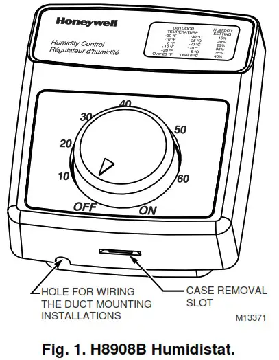
The styling of the H8908 is designed to blend with the latest T8600 family of Honeywell Chronotherm® IV Deluxe Programmable Thermostats. A mounting template is included for mounting the H8908 next to the T8600. The H8908 can also be mounted at any other convenient location in the living area or equipment room. See Fig 1.
NOTE: The H8908 electrical connections are not shared with the thermostat.
Wall Mounting
IMPORTANT
Mount the control in an area with average room temperature and average relative humidity.
The following mounting instructions are for mounting the H8908 on the wall next to the T8600. When installing the H8908 at another location, modify the procedure to fit the installation.
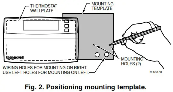
- Hold the mounting template (included) next to the T8600. Select the mounting side for the H8908.
The template is reversible for mounting on either the left or right side of the T8600. See Fig. 2. - Mark the holes for the two mounting screws (included). Then mark the hole for the low voltage wiring on the template that corresponds with the side selected in step 1.
- Remove the template and drill the holes.
- Run low voltage wiring to the location and pull about 6 in. (152 mm) of wire through the hole.
- Plug the hole with nonflammable insulation to prevent drafts from affecting the control operation.
- Remove the H8908 case from the base. See Fig. 1.
- Position the base on the wall with the arrow up.
- Use the two 1 in. (25 mm) mounting screws to secure the base to the wall.
 IMPORTANT
Use 18- to 22-gauge wire for proper wiring. - Connect the low voltage wires to the leads on the H8908.
- Replace the H8908 case.
 IMPORTANT
Duct Mounting
IMPORTANT
When mounting near an elbow area, locate the control 6 in. (152 mm) upstream from the elbow so the element is exposed to the normal airflow (Fig. 3).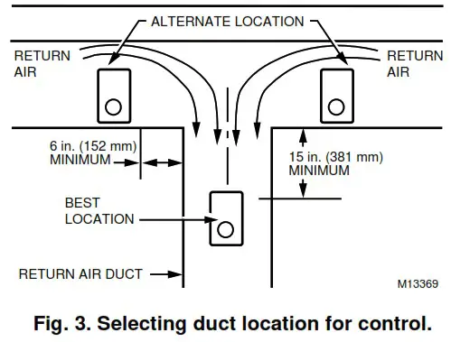
- Locate the control at least 8 in. (203 mm) upstream from the humidifier (or dehumidifier/ventilator supply) in the return air duct. See Fig. 3.
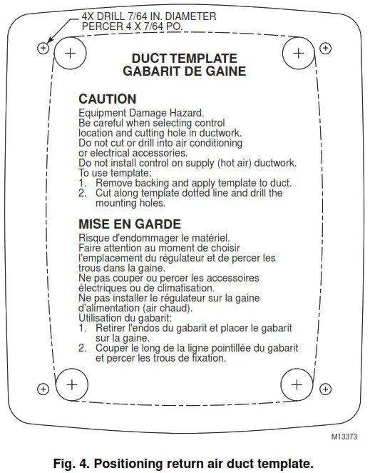
- Apply the duct template to the duct location.
- Use the duct template, Fig. 4, to make the opening and mounting holes for the H8908.
- Remove the H8908 case from the base. See Fig. 1.
- Position the foam gasket on the H8908 base.
- Position the base on the duct with the arrow up.
- Use the four 1 in. (25 mm) mounting screws to secure the base to the duct.
- Connect the low voltage wires to the leads on the H8908.
- Replace the H8908 case.
IMPORTANT
Use 18- to 22-gauge wire for proper wiring.
WIRING
![]() CAUTION
CAUTION
Personal Injury Hazard.
Power supply can cause electrical shock and injury.
Disconnect power supply before installation or servicing.
All wiring must comply with applicable local codes, ordinances and regulations. Make wiring connections according to humidifier (or dehumidifier/ventilator) instructions, if available; otherwise, see typical wiring diagrams in Fig. 5 through 12.
IMPORTANT
Select models of fan centers include humidifer taps so the current sensing relay or sail switch is not needed.
If not using a current sensing relay or sail switch, the humidifier must be energized during blower motor cycles for proper operation.
On multispeed blower applications, do not wire the high voltage side of the transformer to the same power source that services the furnace blower. Premature transformer burnout can occur.
On HE360 fan powered humidifier models, only the two yellow wires are connected to the control. The remaining two red wires are only used with electronic humidity controls.
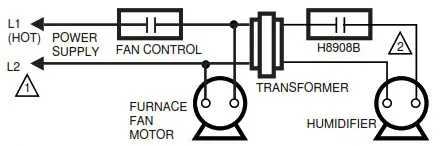
Fig. 5. Typical wiring diagram for system with fan interlock.
![]() POWER SUPPLY. PROVIDE DISCONNECT MEANS AND OVERLOAD PROTECTION AS REQUIRED.
POWER SUPPLY. PROVIDE DISCONNECT MEANS AND OVERLOAD PROTECTION AS REQUIRED.![]() 24 VAC WIRING.
24 VAC WIRING.
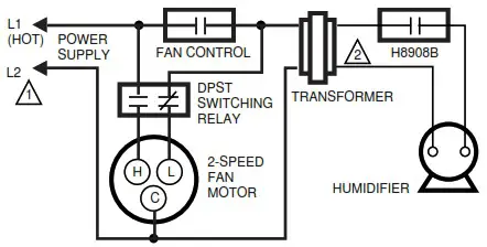
Fig. 6. Typical wiring diagram for system with 2-speed fan motor.
![]() POWER SUPPLY. PROVIDE DISCONNECT MEANS AND OVERLOAD PROTECTION AS REQUIRED.
POWER SUPPLY. PROVIDE DISCONNECT MEANS AND OVERLOAD PROTECTION AS REQUIRED.![]() 24 VAC WIRING.
24 VAC WIRING.
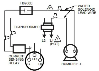
Fig. 7. Typical wiring diagram of current sensing relay with humidifier.
![]() POWER SUPPLY. PROVIDE DISCONNECT MEANS AND OVERLOAD PROTECTION AS REQUIRED.
POWER SUPPLY. PROVIDE DISCONNECT MEANS AND OVERLOAD PROTECTION AS REQUIRED.![]() 24V WIRING.
24V WIRING.
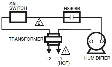
Fig. 8. Typical wiring diagram of sail switch with humidifier.
![]() POWER SUPPLY. PROVIDE DISCONNECT MEANS AND OVERLOAD PROTECTION AS REQUIRED.
POWER SUPPLY. PROVIDE DISCONNECT MEANS AND OVERLOAD PROTECTION AS REQUIRED.![]() 24V WIRING.
24V WIRING.
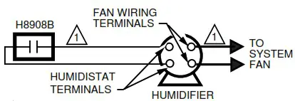
Fig. 9. Typical wiring diagram for steam humidifiers.
![]() 24V WIRING.
24V WIRING.
NOTE: FOLLOW THE INSTALLATION INSTRUCTIONS INCLUDED WITH THE STEAM HUMIDIFIER TO WIRE THE SYSTEM FAN.
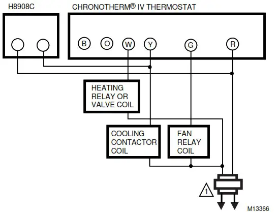
Fig. 10. Typical parallel wiring of humidity controller with Chronotherm® IV Thermostat for dehumidification and mildew control.
![]() PROVIDE OVERLOAD PROTECTION AND DISCONNECT MEANS AS REQUIRED.
PROVIDE OVERLOAD PROTECTION AND DISCONNECT MEANS AS REQUIRED.
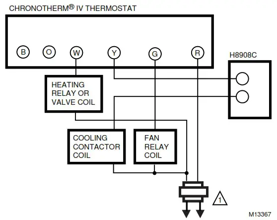
Fig. 11. Typical series wiring of humidity controller with Chronotherm® IV Thermostat for dehumidification and mildew control.
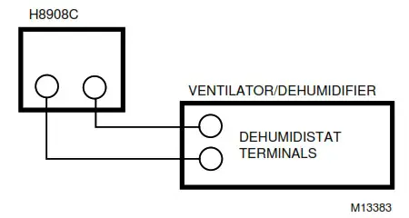
Fig. 12. Typical wiring diagram for HR150, HR200, ER150 and ER200 Ventilator or HD220 Dehumidifier applications.
ADJUSTMENTS
Humidity Control Adjustment
To maintain optimum humidity control without causing condensation on cold surfaces such as windows, the homeowner must adjust the setpoint as the outdoor temperature changes.
To reduce the relative humidity, reduce the setpoint approximately three percent relative humidity every 24 hours. To increase the relative humidity, increase the sepoint approximately three percent relative humidity every 24 hours.
Setpoint Adjustment
Set the humidity setpoint according to the prevailing outdoor temperature. See Table 1 for recommended settings.
Table 1. Recommended Humidity Controller Settings.
| Outdoor Temperature | Recommended Humidity Controller Setting | |
| °F | °C | |
| -20 | -29 | 15 |
| -10 | -23 | 20 |
| 0 | -18 | 25 |
| +10 | -12 | 30 |
| +20 | -7 | 35 |
| >+20 | >-7 | 40 |
OPERATION AND CHECKOUT
Place the system in operation and observe through at least one complete cycle to make certain that all components are functioning properly.
| Home and Building Control Honeywell Inc. Honeywell Plaza P.O. Box 524 Minneapolis, MN 55408-0524 | Home and Building Control Honeywell Limited-Honeywell Limitée 155 Gordon Baker Road North York, Ontario M2H 3N7 |
![]()
69-1341 G.H. 10-99 Printed in Taiwan R.O.C.
www.honeywell.com
firealarmresources.com


