DSR-150N Wireless Services Router Appliance

About This Guide
This guide gives step by step instructions for setting up D-Link DSR-150N Services Router. Please note that the model you have purchased may appear slightly different from those shown in the illustrations.
Unpacking the Product
Open the shipping carton and carefully unpack its contents. Please consult the packing list located in following information to make sure all items are present and undamaged. If any item is missing or damaged, please contact your local D-Link reseller for replacement.
The LEDs reflect device current status. The power LED (A) will keep blinking during device startup period. The whole startup process will take around 1 minute and device may not respond to users’ requests during this time. After startup completion, the power LED (A) will turn to solid green. If you want to restart the device for some instances, we recommend you waiting a couple of few seconds between shutting down and turning on the device. The meaning and status of each LED indicator are shown in the below table:
– One (1) DSR-150N Wireless Services Router
– One (1) 12V/1.5A Power Adapter
– One (1) Console Cable (RJ45-to-DB9 Cable)
– One (1) Ethernet (CAT5 UTP/Straight Through) Cable
– One (1) Reference CD (CD-ROM containing product documentation in PDF format)
Product Overview
DSR-150N Front Panel
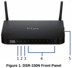
The LEDs reflect device current status. The power LED (A) will keep blinking during device startup period. The whole startup process will take around 1 minute and device may not respond to users’ requests during this time.
After startup completion, the power LED (A) will turn to solid green. If you want to restart the device for some instances, we recommend you waiting a couple of few seconds between shutting down and turning on the device. The meaning and status of each LED indicator are shown in the below table:
# | LED | Color | Status | Description |
A | Power | Green | Solid Green | Completion of power on |
| Light Off | The device is power-off or during power-on process | |||
B | Internet | Green | Solid Green | Link is up |
| Blinking Green | There are activities on this port | |||
| Light Off | Link is down | |||
C | 2.4GHz WLAN | Green | Solid Green | Wireless link is active |
| Light Off | Wireless link is off | |||
D | LAN | Green | Solid Green | Link is up |
| Blinking Green | There are activities on this port | |||
| Light Off | Link is down | |||
E | WPS | Blue | Solid Blue | Connections are established |
| Blinking Blue | Connections setup is processing | |||
| Light off | No connections |
Table 1. DSR-150N LED Status Description
DSR-150N side view: device buttons
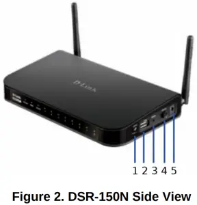
| # | Function | Description |
| 1 | WPS button | Wi-Fi Protected Setup (WPS) System is a simplified method assisting users to setup a secure wireless network during “Initial setup” and“Add New Device” stages. Please refer more detail in the user manual. |
| 2 | USB port (1) | It adheres to USB 2.0 standard and is also compatible to USB 1.1. Now we support below features through this USB port: 1. Flash Disk or Hard Disk for files sharing. 2. Printers for printer sharing. |
| 3 | Reset button | Long press to reset the device. |
| 4 | Power on/off button | Push down this button to turn on the device. |
| 5 | Power jack | DC power jack. |
Table 2. DSR-150N Side Button Description
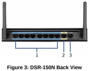
| # | Function | Description |
| A | Fast Ethernet LAN port (1-8) | It connects Ethernet devices, such as computers, switches and hubs |
| B | Fast Ethernet WAN port (1) | One auto MDI/MDIX WAN port used to connect the cable or DSL modem for Internet. |
| C | Console port (1) | It is used to access Command Line Interface (CLI) via RJ45-to- DB9 console Cable. |
Table 3. DSR-150N Back Interface Description
DSR-150N Default Interface Settings:
| Ethernet Interface | Interface Type | IP Address | Web-Based Management | DHCP Server |
| LAN (1-8) WLAN | Static IP | 192.168.10.1 | Enabled | Enabled |
| WAN | DHCP client | 0.0.0.0 | Disabled | Disabled |
Table 4: Default Interfaces Settings
Note: D-Link Services Routers only allow Web GUI access from LAN and WLAN interfaces by default for security reason.
Installing and Connecting the Device
Observe the following precautions to help prevent shutdowns, equipment failures and injuries.
Before You Begin
Observe the following precautions to help prevent shutdowns, equipment failures and injuries:
– Before installation, always check that the power supply is disconnected.
– Ensure that the room in which you operate the device has adequate air circulation and that the room temperature does NOT exceed 40 C (104 F).
– Allow 1 meter (3 feet) of clear space to the front and back of the device.
– Do NOT place the device in an equipment rack frame that blocks the air vents on the sides of the chassis. Ensure that enclosed racks have fans and louvered sides.
– Before installation, please correct these hazardous conditions: moist or wet floors, leaks, ungrounded or frayed power cables, or missing safety grounds.
Connecting Power and Turn the Device On/Off
To connect power to the device, please plug the AC/DC power adapter (shipping along with the box) into the DC power jack on the side of the device.
C Console port (1)
It is used to access Command Line Interface (CLI) via RJ45-toDB9 console Cable.
Note: We recommend using a surge protector for the power connection.
To power on the DSR-150N device, please push down the power button on the side of the device. To power off the device, please push down the power button again, and the power button will recover the non-pressed position.
Connecting the Device to a Network Browser
This section provides basic knowledge of how to connect DSR-150N to network. Necessary connecting cables and steps are shown below:
- Connecting a RJ-45 cable from the port labeled WAN to the external router, cable or ADSL modem. The port WAN is pre-allocated to the WAN network segment.
- Connecting a RJ-45 cable from the port labeled LAN (1-8) to PCs in the LAN network segment.
- Connecting a RJ45-to-DB9 cable from the console port for CLI (Command Line Interface) for management access.


Initially Configure the Device
DSR-150N preinstall services router software and is ready to be further configured after startup completion. Although the device has preconfigured with factory default settings allowing you to initialize connections to the device, we still highly recommend you to customized configurations for your specific network requirements.
Using the Web User Interface
To use the Web User Interface (WebUI) to manage DSR-150N, the workstation from which you manage the device must be in the same subnet as the device.
Browser | Version | |
 | Microsoft Internet Explorer | 6.0 or higher |
 | Mozilla Firefox | 3.5 or higher |
 | Netscape Navigator | 9.0 or higher |
 | Apple Safari | 4.0 and later |
 | Google Chrome | 3.0 and later |
Table 5: Browser Compatibility
To access the device with the WebUI:
- Connect your workstation on the port labeled LAN (1-8), which is pre-allocated to the LAN.
- Ensure your workstation is DHCP Client enabled or manually assigned a static IP address in the 192.168.10.0/24 subnet. Note: Disable pop-up blocking software or add the management IP address http://192.168.10.1 to your pop-up blocker’ allow list.
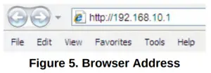
- Launch your browser, enter the IP address for the LAN interface (the factory default IP address is https://192.168.10.1 (for DSR Series Initially Configure the Device routers with WW firmware) or http://192.168.10.1 (for DSR Series routers with DSR-150N preinstall services router software RU firmware)), then press Enter.

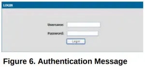
- Log on the Services Router Web Interface The default log on information is:
Username: admin
Password: admin
Using a Console Connection (RJ45-to-DB9 DCE)
The Services Router provides an serial port that enables a connection to a computer or terminal for monitoring and configuring the device. This port is a RJ-45 connector, implemented as a data communication terminal equipment (DCE) connection.
To use the console port connection, you need the following equipment:
- A terminal or a computer with both a serial port and the ability to emulate a terminal.
- A RJ45-to-DB9 RS-232 with female connector. (Already included in packing list).
- If your Laptop or PC doesn’t have RS-232 connector, a converter is required.
Note: DSR-150N does not come with RS-232 converter and these must be purchased separately.
To establish a console connection:
- Plug the RJ-45 connector of the supplied RJ45-to-DB9 cable directly to the console port on the Services Router.
- Connect the other end of the cable to a terminal or to the serial connector of a computer running terminal emulation software. Set the terminal emulation software as following:Baud rate: 115200
Data bits: 8 Parity:
None Stop bits: 1
Flow control: None - When you have correctly set up the terminal, having previously followed the instructions in section “Connecting Power and Turn the Device On/Off” then switch on your device. The boot sequence appears in the terminal.
- Once the boot sequence completes, the command prompt is displayed, the device is ready to be configured.
Finalizing the Configuration
After initial setup, you should refer to the companion publications found in PDF format on the accompanying master CD for more information on how to begin to configure the DSR-150N device.


 Wifi Dsl Modem Router Premium Installation Guide")


