
DELL P2722HE 27 inch Full HD LED LCD Monitor Installation Guide
Disassembly Procedures
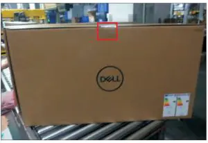
- Open the Pizza carton with a proper tool.

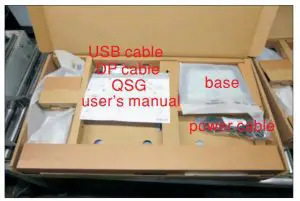
- Take out all of the accessories including DP QSG, cable, power cable, USB cable, CD&user’s manual, stand and EEI label(optinal) from the carton.(Note: It depends on whether users returning the accessories)

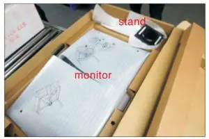
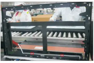
- Take out of the Paper-top from the carton, then take out the packed monitor and packed stand from the Pizza box.

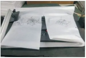
- Take out the monitor from the bag and put it on a protective cushion.

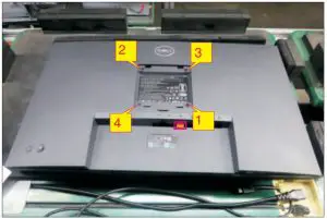
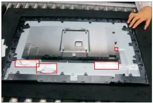
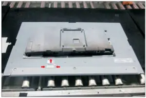
- Use a Philips-head screwdriver to remove four screws for unlocking mechanisms. Remove the DP cap.
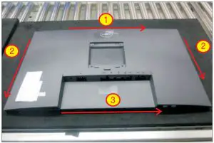
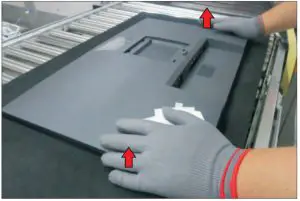
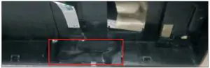
(No.1~4 screw size=M4x10; Torque=12±0.5kgfxcm) - Wedge your fingers between the rear cover and the middle bezel on the corners of the top side of the monitor to release the rear cover, then use one hand to press the middle bezel, the other hand to pull up carefully the rear cover in order of arrow preference for unlocking mechanisms of rear cover..
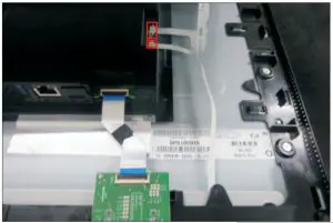
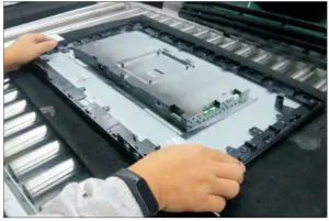
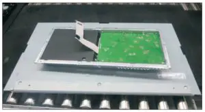
- Lift the rear cover up carefully. Disconnect the key cable and USB FFC cable from the connectors of the interface board, and then remove the rear cover.
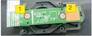
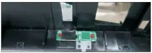
- Use a Philips-head screwdriver to remove 2pcs screws for unlocking the joystick key board unit, then tear off the tapes and release the USB board.
(No.1~2 screw size=M2x3.3,Torque=1±0.2kgfxcm)

- Use a Philips-head screwdriver to remove one screw for unlocking the USB board unit, then release the USB board unit and put it aside.
(No.1 screw size=M3x6, Torque=4±0.5kgfxcm)
- Disconnect the panel lamp cable away from the connectors of the panel module and circuit board, then release the cable by tearing off tape.

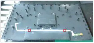
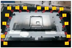
- Use a Philips-head screwdriver to remove 15pcs screws for unlocking the middle bezel.
(No.1~13 screw size=M3x4, Torque=5±0.5kgfxcm;
No.14~15 screw size=M1.6×1.7, Torque=1±0.2kgfxcm) - Disconnect the LED cable from the connector of the board, then tear off 3pcs aluminum foil.
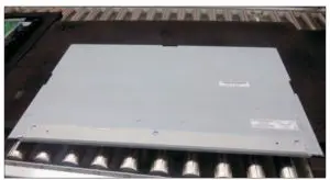
- Take away the middle bezel, and put it on a fixture, then tear off the mylar tape for releasing the LED board.


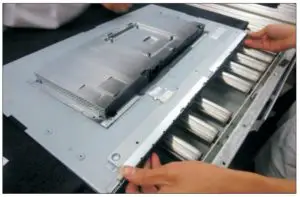
- Lift up the panel with the bracket for releasing the front bezel away from the panel.

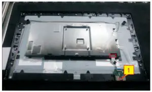
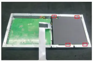
- Use a Philips-head screwdriver to remove 2pcs screws for unlocking the bracket with panel module.
(No.1~2 screw size=M3x4, Torque=5±0.5kgfxcm)
- Put the panel module on a protective cushion, then push the earing-locks and disconnect the LVDS cable from the connector of the panel module.
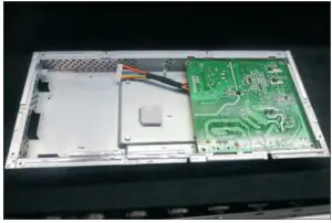
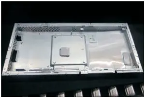
- Take away the bracket chassis module and then put the bracket chassis module on a protective cushion.

- Remove the black Mylar from the hooks of the bracket as the picture below shown.

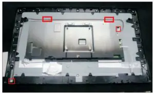
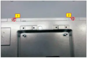
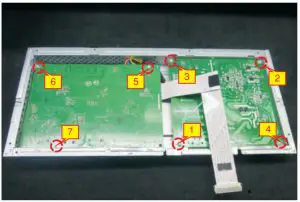
- Use a Philips-head screwdriver to remove 7pcs screws for unlocking the power board and interface board, and then release all the cables from the hooks.
(No.1 screw size=M4x8, Torque=6±0.5kgfxcm;
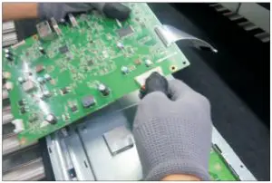
No.2~7 screw size=M3x7.5, Torque=6±0.5kgfxcm) - Remove the interface board and power board from the bracket chassis module carefully, and disconnect all the cables.
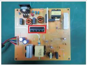
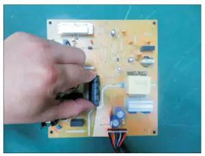
- Remove electrolyte capacitors (red mark) from printed circuit boards.

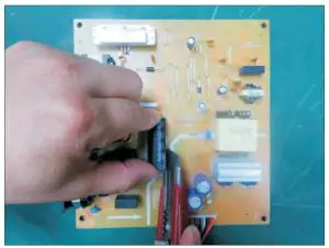
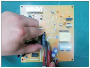
- Cut the glue between bulk cap. and PCB with a knife.
- Ensure cutting path within the glue, don’t touch bulk cap. or PCB.
- Cut into the bottom of bulk cap. and pullit up carefully.
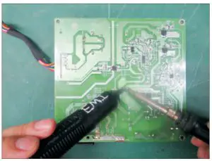
- Take out bulk cap. pin solder with soldering iron and absorber.

- Lift the bulk cap. up and away from the PCB.

- Cut the glue between bulk cap. and PCB with a knife.

Product material information
The following substances, preparations, or components should be disposed of or recovered separately from other WEEE in compliance with Article 4 of EU Council Directive 75/442/EEC.
| Capacitors / condensers (containing PCB/PCT) | No used |
| Mercury containing components | No used |
| Batteries | No used |
| Printed circuit boards (with a surface greater than 10 square cm) | Product has printed circuit boards (with a surface greater than 10 square cm) |
| Component contain toner, ink and liquids | No used |
| Plastic containing BFR | No used |
| Component and waste contain asbestos | No used |
| CRT | No used |
| Component contain CFC, HCFC, HFC and HC | No used |
| Gas discharge lamps | No used |
| LCD display > 100 cm2 | Product has an LCD greater than 100 cm2 |
| External electric cable | Product has external cables |
| Component contain refractory ceramic fibers | No used |
| Component contain radio-active substances | No used |
| Electrolyte capacitors (height > 25mm, diameter > 25mm) | Product has electrolyte capacitors (height > 25mm, diameter > 25mm) |
Tools Required
List the type and size of the tools that would typically can be used to disassemble the product to a point where components and materials requiring selective treatment can be removed.
Tool Description:
- Screwdriver (Phillip head) #1
- Screwdriver (Phillip head) #2
- Penknife
- Soldering iron and absorber


