Disassembly Procedures
S1 Turn n off the monitor.S2 Place the monitor on a soft cloth along with the desk.
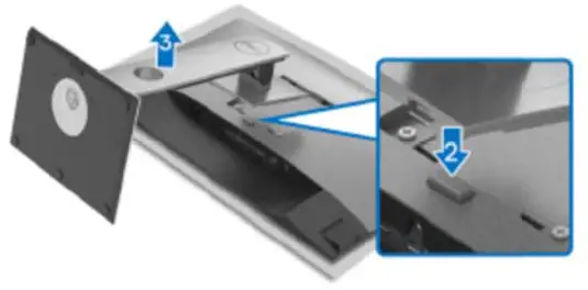
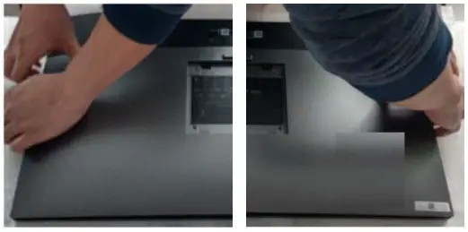
- Removing the monitor stand.
- Place the monitor on a soft cloth or cushion.
- Press and hold the stand release button.
- Lift the stand up and away from the monitor.
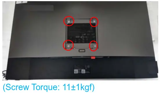
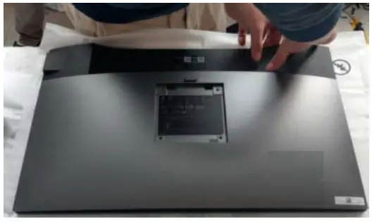
S3 Unlock 4 screws on the Rear Cover.
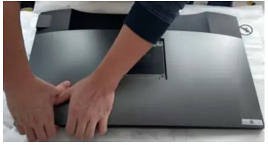
S4 Disassemble Rear Cover from middle frame.
Notice the disassembly order:
- Disassemble the top side.

- Disassemble the Left/Right side.

- Disassemble the bottom side.

- Disassemble Rear Cover from the middle frame.

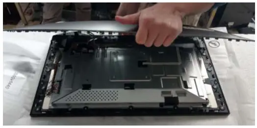
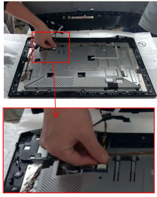
S5 Remove the tape which fixed the USB FFC cable and USB wire on the panel.
S6 Remove USB FFC cable and USB wire from I/F BD.
S7 Tear off the tape from Rear Cover
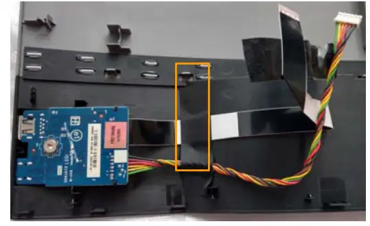
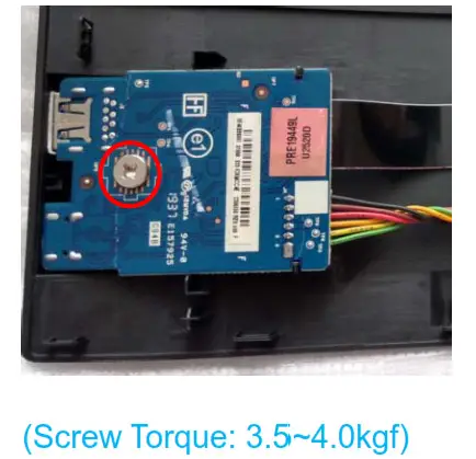
S8 Unlock a screw-on USB BD and take off USB BD from Rear Cover
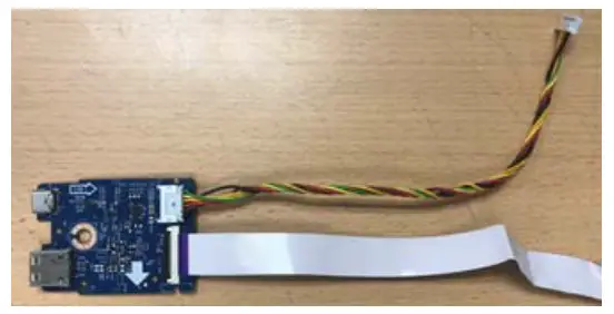
S9 Remove USB FFC cable and USB wire from USB BD.
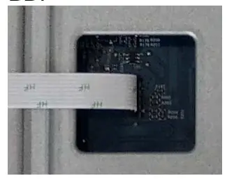
S10 Remove Sensor BD wire from I/F BD and Sensor BD
Disassemble SENSOR BD from the panel.
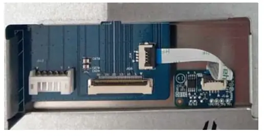
S11 Remove Control BD wire from I/F BD
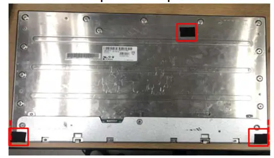
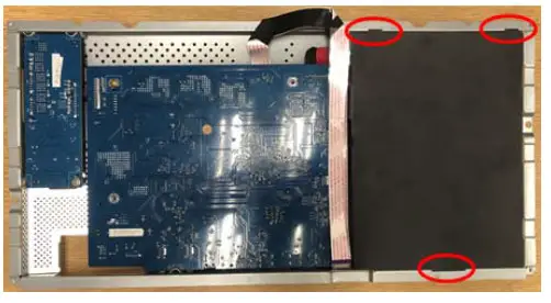
S12 Remove 4 black tapes from Panel.
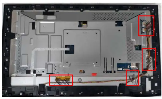
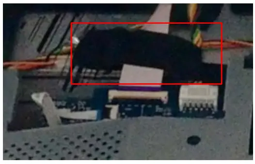
813 Remove long and short backlight wire from LED Driver BD.
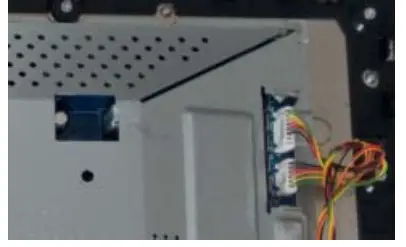
814 Remove 2 tapes that fixed backlight wire from the panel and middle frame.(See mark)
Remove long and short backlight wire from the panel.
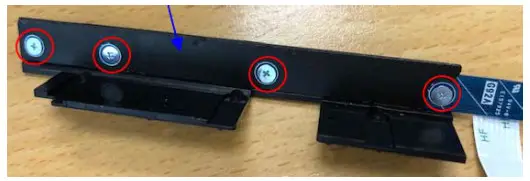
Unlock 1 TP -S screw (See Blue mark) and disassemble a PANEL BOSS from Middle Frame.
Unlock screws on Middle Frame
a. FHP screws*2.(See Green mark)
b. MF BASE screws*3 (See Red mark)
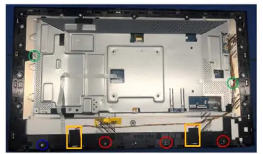
(TP-S Screw Torque: 6.5±0.5kg0 (FPH screw and base Screw Torque: 3.5-4.0kgf)S15 Tear off the yellow tape from Panel and disassemble the LVDS cable from Panel.
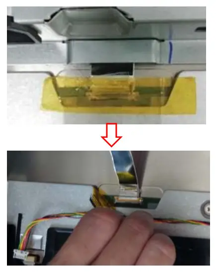
S18 Take off Main SHD from Panel.
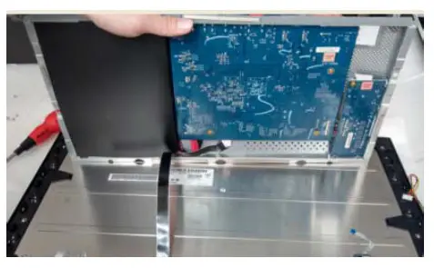
817 Unlock 11 screws on the Middle frame
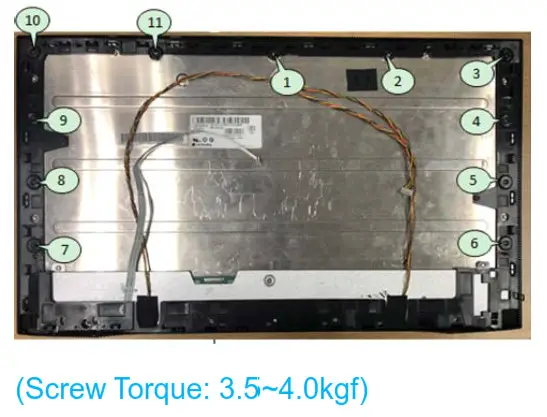
S18 Take off Middle frame from Panel Remove 3 tapes from the panel
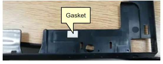
S19 Remove 1 Gasket from Middle Frame
S20 Unlock 3 screws on the middle frame to take off Control BD ASSY.
S21 Tear off Control BD Mylar from Control BD and take off Control BD FFC cable.
Unlock 4 screws on Control BD to disassemble Control BD from Key Button.
(Screw Torque: 1.4-1.45kgf)S22 Take off Mylar from SPS BD.
S23 Unlock 9 PCBA screws.
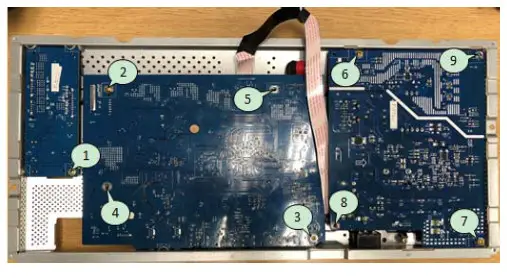
(Screw T Torque: 8.5 5±0.5kgf)
S24 Disassemble LED Driver BD, BD and SPS BD from Main SHD.
Remove all cables and tapes from LED Driver BD. I/F BD and SPS BD.
S25 Unlock 1 Grounding Screw and disassemble AC wire from Main SHD.
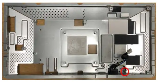 (Screw Torque: 8.5±0.5kgf)
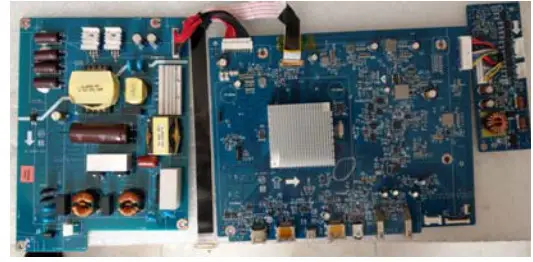
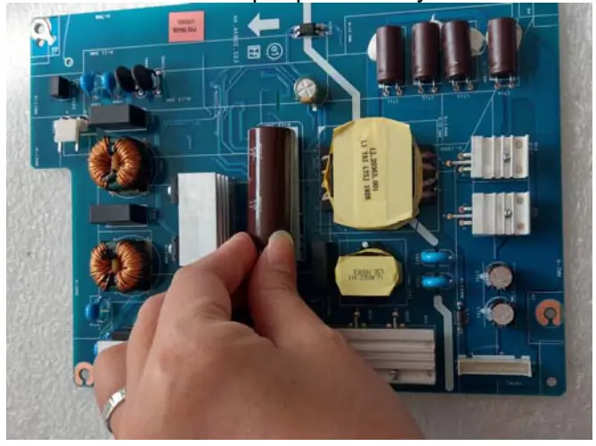
S26 Remove electrolyte capacitors (red mark) from printed circuit boards
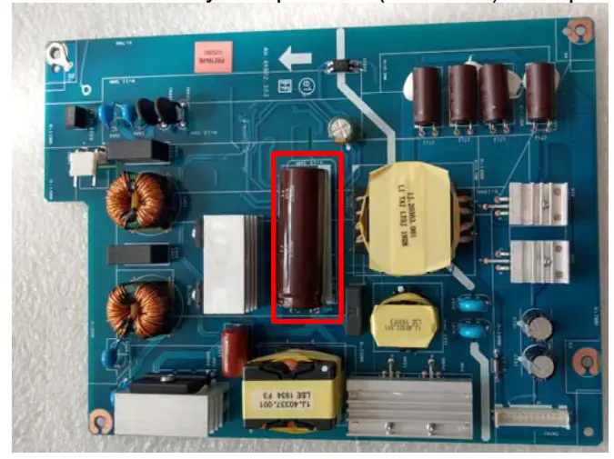
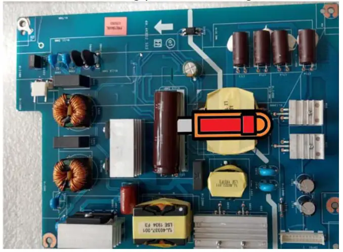
S26-1 Cut the glue between bulk caps. and PCB with a knife
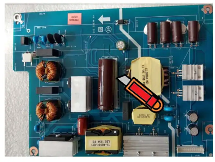
S26-2 Ensure cutting path within the glue. don’t touch bulk cap. or PCB
S26-3 Take out the bulk cap. pin solder withholding iron and absorber
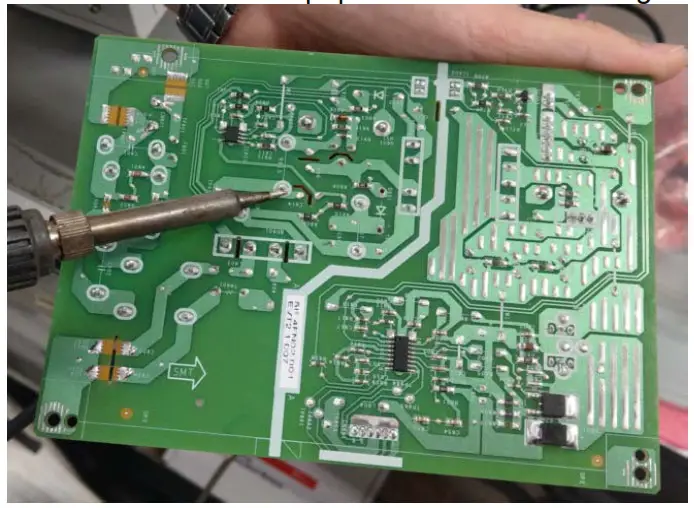
S26-4 Lift the bulk ca . u and away from thel3C B
Product material information
The following substances, preparations, or components should be disposed of or recovered separately from other WEEE in compliance with Article 4 of EU Council Directive 75/442/EEC.
| Capacitors / condensers (containing PCB/PCT) | No used |
| Mercury-containing components | No used |
| Batteries | No used |
| Printed circuit boards (with a surface greater than 10 square cm) | The product has printed circuit boards (with a surface greater than 10 square cm) |
| The component contains toner, ink, and liquids | No used |
| Plastic containing BFR | No used |
| Component and waste contain asbestos | No used |
| CRT | No used |
| Component contain CFC, HCFC,1-1FC and HC | No used |
| Gas discharge lamps | No used |
| LCD display > 100 cm2 | Product has an LCD greater than 100 cm2 |
| External electric cable | Product has external cables |
| Component contains refractory ceramic fibers | No used |
| Component contains radioactive substances | No used |
| Electrolyte capacitors (height > 25mm, diameter > 25mm) | Product has electrolyte capacitors (height >25mm, diameter > 25mm) |
Tools Required
List the type and size of the tools that would typically be used to disassemble the product to a point where components and materials requiring selective treatment can be removed.
Tool Description:
– Screwdriver
– Scraper Bar
– Penknife
– Soldering iron and absorber


![Dell 24 Usb-c Monitor [p2421dc] User Manual](https://static-data1.manualsee.com/1/img/160/17294/2020/12/Dell-24-USB-C-Monitor-P2421DC.jpg "Dell 24 Usb-c Monitor [p2421dc] User Manual")


