
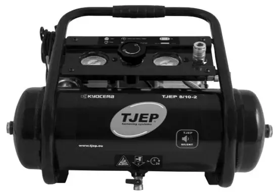
![]() 8-10-2 Connect Fastening Silent Compressor
8-10-2 Connect Fastening Silent Compressor
User Manual
EXPLORE OUR WEBSITE FOR MORE INFORMATION
TJEP 8 / 10 – 2
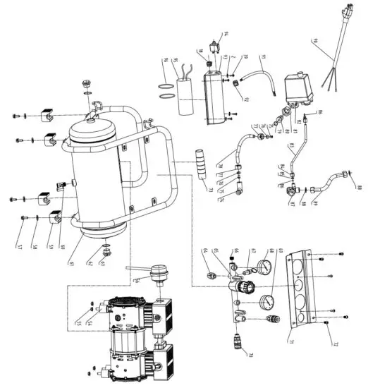
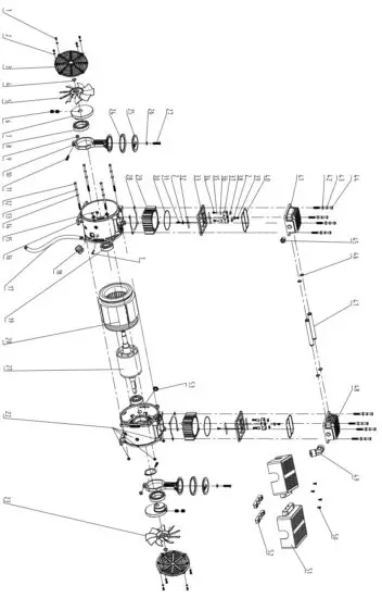
Spare parts
| ITEM NO. | PART NO. | DESCRIPTION |
| 1 | GB/T818 | Cross Recess Pan Head Screw M4*12 |
| 2 | GB/T97.1 | Washer v |
| 3 | MWL10B4P-02A | Fan shroud |
| 4 | G B/T894.1 | Circlips for shaft -14 |
| 5 | MWL10B4P-19 | Fan A |
| 6 | GB/T77 | Bolt M8*8 |
| 7 | MWL10B4P-05 | Crankshaft |
| 8 | G B/T276 | Bearing |
| 9 | GB/T6170 | Hex nut M6 |
| 10 | MWL10B4P-07 | Connecting rod |
| 11 | GB/T70.1 | Hexagon socket cap screws M6X30 |
| 12 | M20B-06 | Hex head bolt M5’117 |
| 13 | GB/T93 | Spring washer 05 |
| 14 | GB/T97.1 | Flat washer 05 |
| 15 | GB/T6170 | Hex nut M4 |
| 16 | MWL10B4P-17 | Crankcase |
| 17 | AC2030BH-IFJ-005D | Power cord |
| 18 | 6N-4 | Strain relief |
| 19 | GB/T276 | Bearing |
| 20 | MWL10A4P.01 | Stator assembly |
| 21 | MWL10B4P.02 | Rotator assembly |
| 22 | GB/T6177.1 | Hexagon nut with flange M5 |
| 23 | MWL10B4P-20 | Fan B |
| 24 | MWL10B4P-06 | Piston ring |
| 25 | MWL10B4P-18 | Piston cap |
| 26 | JB982 | Bonded washer 06 |
| 27 | MW15BG.04-01 | Pattern hexagon socket bolt M6’16 |
| 28 | MWL10B4P-08 | Piston cap gasket |
| 29 | MWL10B4P-09 | Cylinder |
| 30 | MWL10B4P-12 | Cylinder seal |
| 31 | G B/T823 | Cross Recess Pan Head Screw M4″6 |
| 32 | MWL10B4P-03 | Reed valve |
| 33 | MWL10B4P-01 | Valve plate |
| 34 | GB/T818 | Cross Recess Pan Head Screw M3’10 |
| 35 | GB/T97.1 | Flat washer 03 |
| 36 | MWL10B4P-21A | Cushion |
| 37 | MWL10B4P-04B | Reed valve block |
| 38 | G B/T6170 | Hex nut M3 |
| 39 | GB/T818 | Cross Recess Pan Head Screw M4*8 |
| 40 | MWL10B4P-11 | Cylinder cap seal |
| 41 | MWL10B4P-10A | Cylinder A |
| 42 | GB/T97.1 | Flat washer 06 |
| 43 | GB/T93 | Spring washer 06 |
| 44 | GB/T70.1 | Hexagon socket head bolt M6’55 |
| 45 | AC2520BDM.01 E | Cold start valve |
| 46 | MWL10B4P-16 Air pipe seal | 013.5’22 |
| 47 | MWL10B4P-15A | Air pipe |
| 48 | MWL10B4P-10B | Cylinder B |
| 49 | AC1506-155 | Elbow |
| 50 | GB/T845 | Cross recessed Pan head tapping screws ST3.9’19 |
| 51 | MWL10B4P-13B | Pump cover |
| 52 | MWL10B4P-14A | Pipe holder |
| 53 | MWL20B4P-13 | Rubber inserter |
| 54 | MWL20B4P.04 | Rubber cushion |
| 55 | GB/T6183.1 | Special hex nut M8 |
| 56 | AC1506.14K | Air filter |
| 57 | GB/T5783 | Hex bot M6’16 |
| 58 | GB/T96.1 | Flat washer 06 |
| 59 | ACWL1008LBGM4P-07A | Rubber feet |
| 60 | ACW2506BG4P.13C | Drain valve |
| 61 | CWG-08/1.0-00A | Tank assembly |
| 62 | 024.3’02.8 (1008) | 0 ring 024.3’02.8 |
| 63 | ACW2020AH-02A | Inspection port fitting |
| 64 | AC2520BDM-04C | Straight fitting |
| 65 | ACW05038BGM4P.02-02C | Pressure regulator |
| 66 | AC2016BD-13A | Inserter |
| 67 | AC1506.02D5 | Safety valve |
| 68 | AC2030BH-1.01J | Pressure gauge |
| 69 | AC2030BH-1.01J | Pressure gauge |
| 70 | AC1506.060 | Coupler |
| 71 | ACWL1008LBGM4P-01 | Control panel |
| 72 | ACW05038BGM4P-03 | Hexagon plain round head non-slip bolt M6’14 |
| 73 | CWE-16/0.7-03 | Rubber grip |
| 74 | ACW2016BDM-10D | Elbow |
| 75 | AC2016BDM-I-01 | Sleeve |
| 76 | AC1506.11-03A | Ferrule A |
| 77 | AC1506.11-01B | Tube nut |
| 78 | 010’1.25 (1008) | Teflon tube 010*1.25 |
| 79 | Ø15.5*2 (1008) | O ring Ø15.5*2 |
| 80 | ACW05038BGM4P-01B | Fitting |
| 81 | ACW05038BGM4P-02 | Hex loose nut |
| 82 | AC1506.01G | Pressure switch |
| 83 | Ø6*1.25 (1008) | Teflon tube Ø6*1.25 |
| 84 | AC1506.08-01B | Tube nut |
| 85 | AC1506.08-03A | Ferrule B |
| 86 | AC2016BDM-I-01A | Sleeve |
| 87 | AC1506.09W | Check valve |
| 88 | MW05B4P-15A | Sealing |
| 89 | ACWL1008LBGM4P-02 | Exhaust tube assembly |
| 90 | AC2030BH-IFJ-004C | Power cord |
| 91 | AC2030BH-IFJ-004D | Power cord |
| 92 | 5N-4 | Strain relief |
| 93 | CWH-30/0.7-00I-05C | Capacitor case |
| 94 | M20B.02.02W | Thermal protector |
| 95 | M20B.04K | Capacitor |
| 96 | Ø50.5*Ø2.5 (1008) | O ring Ø50.5*Ø2.5 |
Figures
Key parts
![]() IMPROPER AND UNSAFE USE OF THE COMPRESSOR CAN RESULT IN DEATH OR SERIOUS INJURY. IT IS VERY IMPORTANT THAT THE INTENDED OPERATOR OF THE COM-PRESSOR READS AND UNDERSTANDS THIS MANUAL BEFORE OPERATING THE COMPRESSOR. KEEP THIS MANUAL AVAILABLE FOR OTHERS BEFORE THEY USE THE COMPRESSOR.
IMPROPER AND UNSAFE USE OF THE COMPRESSOR CAN RESULT IN DEATH OR SERIOUS INJURY. IT IS VERY IMPORTANT THAT THE INTENDED OPERATOR OF THE COM-PRESSOR READS AND UNDERSTANDS THIS MANUAL BEFORE OPERATING THE COMPRESSOR. KEEP THIS MANUAL AVAILABLE FOR OTHERS BEFORE THEY USE THE COMPRESSOR.
Please keep this manual in a safe place for future reference.
Important safety information
The manufacturer cannot possibly anticipate every possible circumstance that might involve a hazard. The warnings in this manual and the tags and decals affixed to the compressor are, therefore, not exhaustive. If you use a procedure, work method, or operating technique that the manufacturer does not specifically recommend, you must make sure that it is safe for you and others. You must also make sure that the procedure, work method, or operating technique that you choose does not render the compressor unsafe.
Figures
Please find the relevant figures referenced in the instructions on page 8.
Technical specifications
| Technical info. | TJEP 8/10-2 |
| Tank size | 8 L |
| Power | 230V 50Hz 1.0 HP |
| RPM | 1400 |
| Rating Amps | 3 |
| Working pressure | 7.0 – 9.0 bar |
| Motor type | Induction |
| Oil-free/Oil lube | Oil-free |
| Quick coupler | 2 |
| Drain valve | Ball valve |
| Duty cycle | 0.75% |
| LPA | 58 dBA |
| LWA | 71 dBA |
As we are constantly developing and improving our products, the information in this overview is subject to change without notice.
Updated information can be found at www.tjep.eu
Tool application
- Pneumatic nailers and staplers
Declaration of conformity
We;
Chongqing Hybest Tools Group Co. Ltd., No. 157, Jienan Street, Banan District, Chongqing, China
declare under our sole responsibility that the;
TJEP 8/10-2 compressor
conforms with the directive(s), its amedment(s) and standard(s);
2006/42/EC, 2014/30/EU.
EN ISO 12100: 2010, EN 1012-1:2010, EN 60204-1:2018, EN IEC 61000-6-2:2019, EN IEC 61000-6-4:2019, EN 61000-3-2:2014,
EN 61000-3-3:2013, EN ISO 13857: 2019, EN ISO 13849-1:2015, EN 13854:2019, EN ISO 14120:2015.
Authorized contact in EU to compile the Technical File;
KGK A/S, Møllevej 9 – H2, DK-2990 Nivå, Tel: +45 45 76 17 00, Mr. Måns Spånberg
Serial number can be found on the front page.
Document ref. No. CQ-2034-MD-DOC · Date: 31/08/2020
ZHAOZIBIN
Quality Manager, Chongqing Hybest Tools Group Co. Ltd., Chongqing, China
Explanation of symbols
| Symbols in manual | |
| The safety alert symbol indicates a potential hazard to personal injury. A signal word (DANGER, WARNING, or CAUTION) is used with the alert symbol to designate a degree or level of hazard seriousness. A safety symbol may be used to represent the type of hazard. The signal word NOTICE is used to address practices not related to personal injury. DANGER: Indicates a hazard that, if not avoided, will result in death or serious injury. WARNING: Indicates a hazard that, if not avoided, could result in death or serious injury. CAUTION: Indicates a hazard that, if not avoided, could result in minor or moderate injury. | |
| Read and understand compressor labels and manual. Failure to follow warnings could result in serious injury. | |
| Operators and others in the work area shall wear impact-resistant eye protection with side shields. | |
| Operators and others in the work area shall wear hearing protection. | |
| It is recommended that the operator and others in the work area wear a CE-marked helmet at the job site. | |
| Symbols on compressor | |
| Read and understand compressor labels and manual. Failure to follow warnings could result in serious injury. | |
| This compressor is CE-approved according to applicable standards. | |
| Dispose of the product according to the WEEE directive. | |
| The product complies with RoHS regulations | |
| Tank capacity | |
| Rounds per minute | |
| Maximum pressure | |
| Power consumption | |
| Risk of the bursting tank if operating above maximum operating pressure. | |
| Risk of fire. Never operate near flammable gasses or vapor. | |
| Risk of an accidental start-up in case of a black-out and subsequent reset. Keep clear of rotating parts. | |
| Risk of eye injury. Always wear CE-approved safety glasses when operating the compressor. | |
| The risk of electrical shock could result in death or serious injury. Only connect the compressor to a properly grounded receptacle. | |
| Risk of high temperatures | |
| Pressure discharge. Keep body parts and bystanders away | |
| Drain tank min 2 times a day. | |
Key parts
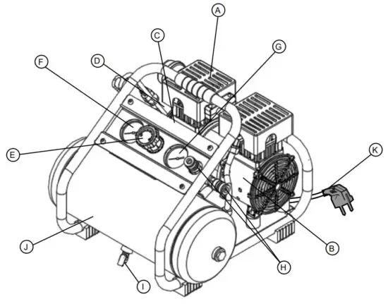
| Parts description – see drawing on page 8 | |
| A | AIR COMPRESSOR PUMP: The pump compresses the air and discharges it into the tank via the piston that moves up and down in the cylinder. |
| B | ELECTRIC MOTOR: The motor is used to power the pump. It is equipped with a thermal overload protector. If the motor overheats for any reason, the thermal overload protector will shut it down in order to prevent the motor from being damaged. |
| C | SAFETY VALVE: This valve is used to prevent the compressor from building too much pressure. If the pressure reaches the preset level in the tank, it will automatically pop open. |
| D | PRESSURE SWITCH: This switch turns on the compressor and is operated manually. When in the ON position, it allows the compressor to start-up or shut down automatically, without warning, upon air demand. ALWAYS set this switch to OFF when the compressor is not being used and before unplugging the compressor. |
| E | PRESSURE REGULATOR: The regulator is used to adjust the pressure inside the line to the tool that is being used. Turn the knob clockwise to increase the pressure and counter-clockwise to decrease the pressure. |
| F | TANK PRESSURE GAUGE: The gauge measures the pressure level of the air that is stored in the tank. It cannot be adjusted by the operator and it does not indicate the pressure inside the line. |
| G | OUTLET PRESSURE GAUGE: The gauge measures the regulated outlet pressure. |
| H | QUICK COUPLER: The quick coupler is connected to a quick connector which is connecting to air hose. |
| I | DRAIN VALVE: The drain valve is used to remove moisture from the air tank after the compressor is shut off. |
| J | AIR TANK: The tank is where the compressed air is stored. |
| K | POWER CORD: This product is for use on a nominal 230-volt circuit and should be grounded. A cord with a grounding plug must be used. Make sure that the product is connected to a grounded outlet that has the same configuration as the plug (see Fig. A). No adapter should be used with this product. Check with a licensed electrician if the grounding instructions are not understood or if there is doubt as to whether the product is properly grounded. If the plug does not fit the outlet, have a properly grounded plug installed by a licensed electrician. |
![]() DANGER: Improper installation of the grounding plug will result in a risk of electric shock. If repair or replacement of the cord or plug is necessary, do not connect the grounding wire to either flat blade terminal. The outer surface of the grounding wire is mixed with yellow and green.
DANGER: Improper installation of the grounding plug will result in a risk of electric shock. If repair or replacement of the cord or plug is necessary, do not connect the grounding wire to either flat blade terminal. The outer surface of the grounding wire is mixed with yellow and green.
General safety warnings
![]() • Do not operate the compressor until you have read and understood this instruction manual for safety, operation, and maintenance instructions.
• Do not operate the compressor until you have read and understood this instruction manual for safety, operation, and maintenance instructions.
![]() WARNING:
WARNING:
- The risk of fire caused by sparks from the motor and pres-sure switch could result in death or serious injury.
- Do not operate the compressor near flammable gas or vapor. Never store flammable liquids or gas in the vicinity of the compressor.
- High-pressure air could result in death or serious injury. Shut off the unit, unplug and release air pressure prior to servicing.
- Never operate above the maximum operating pressure of the nailer/stapler.
- Drain water from the tank after each use.
- Do not weld or repair the tank.
- Do not operate with a pressure switch or safety valve set above the maximum allowable working pressure.
- Hot compressor surfaces could result in serious injury. Allow the compressor to cool before touching.
- Using a compressor to supply breathing air could result in death or serious injury.
- Do not spray flammable materials in the vicinity of any flame or ignition sources including the compressor.
- Do not restrict compressor ventilation openings or place objects against or on top of the compressor
- Operate compressor only in a clean, dry, well-ventilated area.
- Do not operate unattended. Always turn off and unplug the compressor when not in use.
 Risk of serious eye injury from moisture and debris. Operators and others in the work area shall wear CE-approved and impact-resistant eye protection with side shields when working with the compressor and/or opening the drain valve.
- Do not spray any part of the body.
- Shock risk could result in death or serious injury. Only connect the compressor to a properly grounded receptacle.
 Dust can be created when cutting, sanding, drilling, or grinding materials such as wood, paint, metal, concrete, cement, or another masonry. To reduce your exposure
  to these chemicals, work in a well-ventilated area and ALWAYS wear approved safety equipment.
- KEEP CHILDREN AWAY FROM THE COMPRESSOR AT ALL TIMES.
![]() CAUTION:
CAUTION:
- High-pressure air containing water condensation could result in minor or moderate injury. Do not spray at any person.
NOTICE:
- If the pump has been transported or turned upside down (even partially), allow the pump to sit in a normal, upright position for approximately 10 minutes before starting.
Assembly instructions
- Unpack the compressor. Inspect the compressor for damages. If the compressor has been damaged, contact your TJEP dealer immediately.
- Check the air compressor’s identification label to ensure that you have purchased the intended model and that it has the required pressure rating for its intended use.
- The carton should contain the compressor and these safety and operation instructions.
Positioning of the air compressor
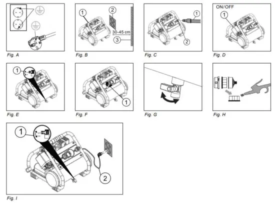
- Position the air compressor (1) near an electrical outlet (2) (Fig. B).
- The compressor must be at least 31 cm from any wall (3) or obstruction, in a clean, well-ventilated area to ensure sufficient airflow and cooling (Fig. B).
- Place the compressor on the floor or a hard, level surface. The compressor must be level to ensure proper drainage of the moisture in the tank.
Connect the air hose to the compressor
- Connect the air hose (1) to the compressor’s quick coupler (2) (Fig. C).
Operating instructions
Break in the pump
- Set the pressure switch (1) to the OFF position (Fig. D).
- Open tank drain valve (1) by turning it counter-clockwise to permit the air to escape and prevent air pressure build-up in the air tank during the break-in period (Fig.
- Turn the pressure knob (1) clockwise until it stops (Fig. F).
- Plug in the power cord
∙ Use a dedicated circuit. If any other electrical devices are drawing from the compressor’s circuit, the compressor may fail to start or an overloaded circuit can result in sluggish starting that causes the motor overload protection system or circuit breaker to trip, especially in cold conditions.
∙ Disconnect the power cord only after the break-in process has been completed, otherwise, the motor might get damaged. - Set the pressure switch (1) to the ON position (Fig.
D). The compressor will start. Run the compressor for 30 minutes. If it fails, turn it off immediately and contact your local TJEP-dealer.
Please note that breaking in the unit is only required prior to first use. - After 30 minutes, turn off the pressure switch.
- Close the tank drain valve (1) by turning it clockwise (Fig. E).
- Set the pressure switch to the ON position. (Fig. D) The air receiver will fill to “cut-out” pressure and then the compressor’s motor will stop. The compressor is now ready for use.
Before each start-up
- Set the pressure switch (1) to the OFF position (Fig.D).
- Turn the pressure regulator knob (1) counterclockwise until it stops (Fig. F).
- Attach hose and accessories (Fig. C).
How to start
- Close the tank drain valve (1) (Fig. I)
- Plug in the power cord (2) (Fi. I)
- Set the pressure switch to the ON position and allow the tank pressure to build (Fig. D). The motor will stop when tank pressure reaches cut-out pressure.
- Turn the air pressure regulator knob clockwise until the desired pressure is reached (Fig. F).
- The compressor is ready for use.
How to shut down
- Set the pressure switch (1) to the OFF position (Fig. D).
- Unplug the power cord (2) (Fig. I).
- Set the tank drain valve (1) to ON to ensure the tank is drained (Fig E).
Maintenance
| Item | Description / reason | Service interval |
| Drain the tank | Through the normal operation of your compressor, condensation of water will accumulate in the tank. To prevent corrosion of the tank from the inside, condensation must be drained twice a day. Be sure to wear safety glasses. Relieve the air pressure in the system then opens the drain valve on the bottom of the tank to rain. Under cold conditions, it is especially important to drain the tank after each use to reduce the chance of problems resulting from the freezing of condensation water. NOTE: Refer to instructions on how to drain the tank. | Twice a day |
| Test for leaks | Check that all connections are tight. Small leaks in the tank, hoses, connections, or transfer tubes will substantially reduce the compressor and tool performance. Spray a small amount of soapy water around the area of suspected leaks with a spray bottle. If bubbles appear, repair, replace, or reseal the faulty component. Do not over-tighten any connections. | Monthly |
| Clean the air filter | A dirty air filter will reduce compressor performance and life. To avoid contaminating the pump, the filter should be cleaned frequently and replaced on a regular basis. Clean the cartridge filter by blowing it on it with a blow gun. NOTE: Refer to instructions on how to clean the air filter. | Weekly |
Storage
Before storing the air compressor:
- Drain tank
- Use an air blow gun to clean all dust and debris from the compressor.
- Disconnect and wind up the power cord.
- Clean the ventilation openings on the motor enclosure with a damp cloth.
- Drain all moisture from the tank.
- Pull the pressure safety valve to release all pressure from the tank.
WARNING:
- Storage covers could cause a fire resulting in death or serious injury.
- Do not place a storage cover over a hot air compressor.
- Let equipment cool for a sufficient time before placing the cover on the equipment.
- Store the air compressor in a clean and dry location.
- In cold weather, store the compressor in a warm building when it is not in use.
This will reduce problems related to starting the motor and the freezing of water condensation.
How to drain the tank
- Set the pressure switch (1) to the OFF position (Fig. D).
- Unplug the power cord (2) (Fig. I).
- Turn the air pressure regulator knob counter-clockwise to set the outlet pressure to zero (Fig. F)
- Place a suitable container under the unit to catch water. 5. Slightly tilt the unit and gently turn the drain valve counterclockwise to open. (Fig. G)
- After the water has been drained, close the drain valve (clockwise) (Fig. G). The air compressor can now be stored.
How to clean the air filter
A dirty filter will reduce the unit s performance and life.
To avoid any contamination inside the pump, the filter should be cleaned weekly and replaced on a regular basis. The cartridge filter should be cleaned with a blow gun (Fig. H).
Troubleshooting
| Problem | Problem | Solutions |
| The motor will not run or start | The power cord is not plugged in. | Plug the power cord into a grounded outlet. |
| The pressure switch is in the O (OFF) position. | Set the pressure switch to the ON position. | |
| The extension cord is the wrong wire gauge or is too long. | Check extension cord information for the proper wire gauge and cord length. | |
| The motor’s thermal overload protection has tripped. | Turn the air compressor off, unplug the power cord and wait until the motor has cooled down. Plug in the power cord only after the motor has cooled down, and wait at least 5 minutes to make sure the thermal overload protector has recovered. | |
| A fuse has blown or a circuit breaker has been tripped. | Replace the fuse or reset the circuit breaker. | |
| Verify that the fuse has the proper amperage. | ||
| Check for low voltage conditions. | ||
| Disconnect any other electrical appliances from the circuit or operate the compressor on a dedicated circuit. | ||
| The air tank pressure exceeds the preset pressure switch limit. | The motor will start automatically when the tank pressure drops below the cut-in pressure. | |
| The safety valve is stuck open. | Clean or replace the safety valve. | |
| Electrical connections are lost. | Contact your TJEP dealer for repair | |
| The motor, capacitor, or safety valve is defective. | Contact your TJEP dealer for repair | |
| The motor runs continuously when the pressure switch is in the ON position. | The pressure switch does not shut off the motor when the air compressor reaches the cut-out pressure and the safety valve activates. | Set the pressure switch to the OFF position. If the motor does not shut off, unplug the air compressor. If the pressure switch is defective, replace it. |
| The compressor’s capacity is not enough. | Check the air requirements of the accessory that is being used. If it is higher than the airflow (liter per minute) and pressure supplied by the compressor, a larger capacity compressor is needed. | |
| The regulator does not regulate the pressure. | The regulator or its internal parts are dirty or damaged. | Replace the regulator. |
| The pressure is low or there is not enough air. | There is a leak at one of the fittings. | Check the fittings with soapy water. Tighten or reseal leaking fittings (apply plumber s tape on threads). Do not over tighten. |
| The tank drain valve is open. | Close the drain valve. | |
| The air intake is restricted. | Clean or replace the air filter elements. | |
| Prolonged excessive use of air. | Decrease the amount of air used. | |
| There is a hole in the air hose. | Check the air hose and replace it if necessary. | |
| The tank leaks. | Replace the tank immediately. Do not attempt to repair it. | |
| The valve is leaking. | Check for worn parts and replace them if necessary. | |
| There is moisture in the discharge air. | There is condensation in the air tank caused by a high level of atmospheric humidity or because the compressor has not been running long enough. | Drain the air tank. Drain the air tank more often in humid weather and use an air-line filter. |
| The compressor overheats. | The ventilation is inadequate. | Relocate the compressor to an area with cool, dry and well-circulated air. |
| Cooling surfaces are dirty. | Clean all cooking surfaces on the pump and the motor thoroughly. | |
| The valve is leaking. | Replace worn parts and reassemble using the new plumber’s tape. | |
| For failure other than the above situations, please stop using the compressor and contact your local TJEP dealer for service. | ||
![]()
KYOCERA UNIMERCO Fastening A/S
Drejervej 2
DK-7451 Sunds
Tlf. +45 97 14 14 40
Fax +45 97 14 14 86
[email protected]
www.tjep.eu
References
 Cutting tools and measuring tools for all industries - KYOCERA UNIMERCO
 Bevestigingsmiddelen voor elke opdracht
-
TJEP Nagler / Nagelgeräte für den professionellen Handwerker
-
Sømpistoler, dykkerpistoler, klammepistoler og kompressor fra TJEP
-
Gas Nailers, Framing Nailers, Finish Nailers and Staplers from TJEP
-
Page d'accueil
-
Spikerpistoler, dykkertpistoler, krampepistoler og kompressor fra TJEP
-
Spik-, dyckert- och klammerpistoler från TJEP


