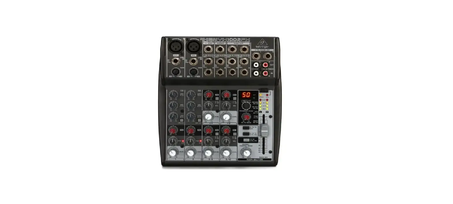
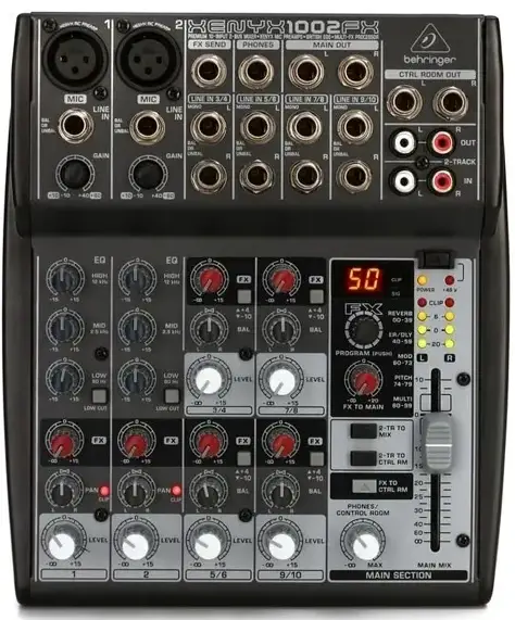
behringer XENYX 1002SFX Premium Analog 10 12-Input Mixer

Important Safety Instructions
 Terminals marked with this symbol carry electrical current of sufficient magnitude to constitute risk of electric shock. Use only high-quality professional speaker cables with ¼” TS or twist-locking plugs pre-installed. All other installation or modification should be performed only by qualified personnel.
 This symbol, wherever it appears, alerts you to the presence of uninsulated dangerous voltage inside the enclosure – voltage that may be sufficient to constitute a risk of shock.
- This symbol, wherever it appears, alerts you to important operating and maintenance instructions in the accompanying literature. Please read the manual.
Caution: - To reduce the risk of electric shock, do not remove the top cover (or the rear section). No user serviceable parts inside. Refer servicing to qualified personnel.
- To reduce the risk of fire or electric shock, do not expose this appliance to rain and moisture. The apparatus shall not be exposed to dripping or splashing liquids and no objects filled with liquids, such as vases, shall be placed on the apparatus.
- These service instructions are for use by qualified service personnel only. To reduce the risk of electric shock do not perform any servicing other than that contained in the operation instructions. Repairs have to be performed by qualified service personnel.
- Read these instructions.
- Keep these instructions.
- Heed all warnings.
- Follow all instructions.
- Do not use this apparatus near water.
- Clean only with dry cloth.
- Do not block any ventilation openings. Install in accordance with the manufacturer’s instructions.
- Do not install near any heat sources such as radiators, heat registers, stoves, or other apparatus (including amplifiers) that produce heat.
- Do not defeat the safety purpose of the polarized or grounding-type plug. A polarized plug has two blades with one wider than the other. A grounding-type plug has two blades and a third grounding prong. The wide blade or the third prong are provided for your safety. If the provided plug does not fit into your outlet, consult an electrician for replacement of the obsolete outlet.
- Protect the power cord from being walked on or pinched particularly at plugs, convenience receptacles, and the point where they exit from the apparatus.
- Use only attachments/accessories specified by the manufacturer.
- Use only with the cart, stand, tripod, bracket, or table specified by the manufacturer, or sold with the apparatus. When a cart is used, use caution when moving the cart/apparatus combination to avoid injury from tip-over.
- Unplug this apparatus during lightning storms or when unused for long periods of time.
- Refer all servicing to qualified service personnel. Servicing is required when the apparatus has been damaged in any way, such as power supply cord or plug is damaged, liquid has been spilled or objects have fallen into the apparatus, the apparatus has been exposed to rain or moisture, does not operate normally, or has been dropped.
- The apparatus shall be connected to a MAINS socket outlet with a protective earthing connection.
- Where the MAINS plug or an appliance coupler is used as the disconnect device, the disconnect device shall remain readily operable.
 Correct disposal of this product: This symbol indicates that this product must not be disposed of with household waste, according to the WEEE Directive
(2012/19/EU) and your national law. This product should be taken to a collection center licensed for the recycling of waste electrical and electronic equipment (EEE).
The mishandling of this type of waste could have a possible negative impact on the environment and human health due to potentially hazardous substances that are generally associated with EEE. At the same time, your cooperation in the correct disposal of this product will contribute to the efficient use of natural resources. For more information about where you can take your waste equipment for recycling, please contact your local city office, or your household waste collection service.- Do not install in a confined space, such as a book case or similar unit.
- Do not place naked flame sources, such as lighted candles, on the apparatus.
- Please keep the environmental aspects of battery disposal in mind. Batteries must be disposed-of at a battery collection point.
- This apparatus may be used in tropical and moderate climates up to 45°C.
LEGAL DISCLAIMER
Music Tribe accepts no liability for any loss which may be suffered by any person who relies either wholly or in part upon any description, photograph, or statement contained herein. Technical specifications, appearances and other information are subject to change without notice. All trademarks are the property
of their respective owners. Midas, Klark Teknik, Lab Gruppen, Lake, Tannoy, Turbosound, TC Electronic, TC Helicon, Behringer, Bugera, Aston Microphones and Coolaudio are trademarks or registered trademarks of Music Tribe Global Brands Ltd. © Music Tribe Global Brands Ltd. 2022 All rights reserved.
LIMITED WARRANTY
For the applicable warranty terms and conditions and additional information regarding Music Tribe’s Limited Warranty, please see complete details online at community.musictribe.com/pages/support#warranty.
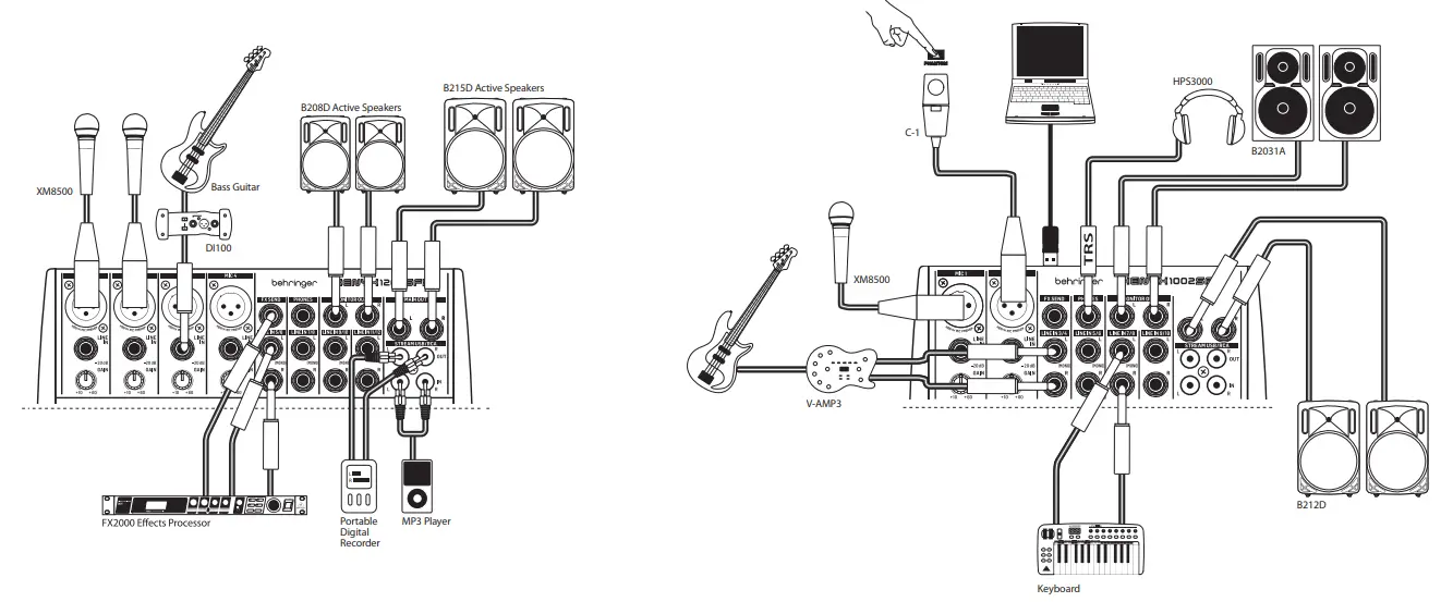
XENYX 1002SFX / XENYX 1202SFX Hook-up
Step 1: Hook-Up

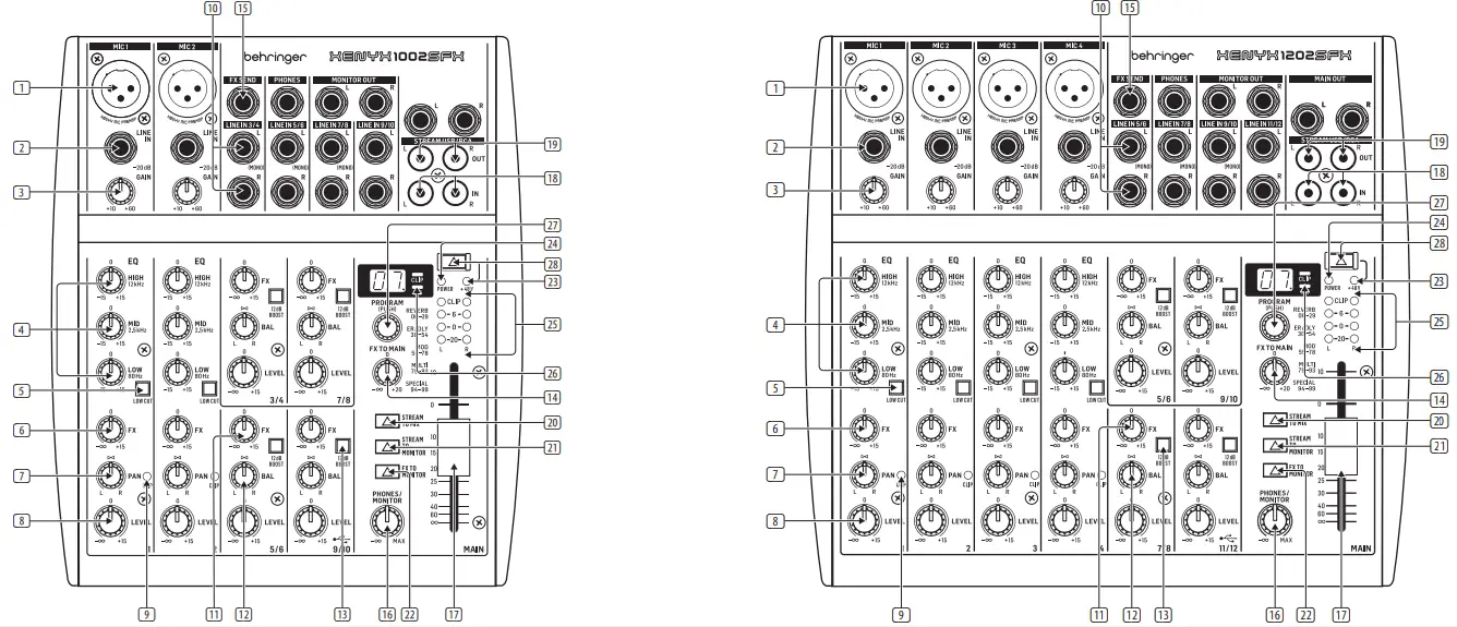
XENYX 1002SFX / XENYX 1202SFX Controls


Step 2: Controls
This chapter describes the various control elements of your mixing console. All controls, switches and connectors will be discussed in detail.
- MIC – Each mono input channel offers a balanced microphone input via the XLR connector and also features switchable +48 V phantom power supply for condenser microphones. The preamps provide undistorted and noise-free gain as is typically known only from costly outboard preamps.
- LINE IN – Each mono input also features a balanced line input on a ¼” connector. Unbalanced devices (mono jacks) can also be connected to these inputs. Please remember that you can only use either the microphone or the line input of a channel at any one time. You can never use both simultaneously!
- GAIN – Use the GAIN control to adjust the input
gain. This control should always be turned fully counterclockwise whenever you connect or disconnect a signal source to one of the inputs. Turn the GAIN knob up while singing or playing until the loudest peaks cause the CLIP LED to light briefly, then turn the knob down slightly. - EQ – All mono input channels include a 3-band equalizer. All bands provide boost or cut of up to 15 dB. In the central position, the equalizer is inactive.
- LOW CUT – In addition, the mono channels are equipped with a steep LOW CUT filter designed to eliminate unwanted low- frequency signal components.
- FX – FX sends enable you to feed signals via a variable control from one or more channels and sum these signals to a bus. The bus appears at the console’s FX send output and can be fed from there to an external effects device. The return from the effects unit is then brought back into the console on the stereo channels. If returning an external FX via a stereo channel, be careful to keep the FX control of that channel at minimum to prevent feedback in the FX loop. Each FX send is mono and features up to
+ 15 dB gain. The FX send is routed directly to the built-in effects processor. - PAN – The PAN control determines the position of the channel signal within the stereo image. This control features a constant-power characteristic, which means the signal is always maintained at a constant level, irrespective of position in the stereo panorama.
- LEVEL – The LEVEL control determines the level of the channel signal in the main mix.
- CLIP – The CLIP LEDs of the mono channels illuminate when the input signal is driven too high, which could cause distortion. If this happens, use the GAIN control to reduce the preamp level until the LED does not light anymore.
- STEREO LINE IN – Each stereo channel has two balanced line level inputs on ¼” jacks for left and right channels. If only the jack marked “L” (left) is used, the channel operates in mono. The stereo channels are designed to handle typical line level signals. Both inputs will also accept unbalanced jacks. The USB audio will be routed to the last pair of stereo channels. Inserting a jack connector will disconnect the USB signal and select the audio from the jack. The Left (MONO) function is not available on the last stereo channel.
- FX – The FX sends of the stereo channels function similar to those of the mono channels. However, since the FX send buses are both mono, a mono sum is first taken from the stereo input before it is sent to the FX bus.
- BAL – The BAL(ANCE) control determines the levels of left and right input signals relative to each other before both signals are then routed to the main stereo mix bus. If a channel is operated in mono via the left line input, this control has the same function as the PAN control used in the mono channels.
- 12 dB BOOST – The stereo inputs have this switch to help match home-recording level inputs to studio level inputs.
- FX TO MAIN – The FX TO MAIN control feeds the built-in effects signal into the main mix. If the control is turned all the way counterclockwise, no effects signal is present in the sum signal of the mixing console.
- FX SEND – The FX SEND connector outputs the signal you picked up from the individual channels using the FX controls. You can connect this to the input of an external effects device in order to process the FX bus’ master signal. Once an effects mix is created, the processed signal can then be routed from the effects device outputs back into a stereo input.
- PHONES/MONITOR – The stereo PHONES jack (at the top of the connector panel) is where you connect headphones. The unbalanced MONITOR OUT jacks carry the main mix signal (including FX) or if selected, just the STREAM or FX signal. The PHONES/MONITOR control adjusts the level of both headphones and main monitor outputs.
- MAIN MIX – The MAIN OUT connectors are balanced mono jacks. The MAIN MIX fader adjusts the volume of these outputs.
- STREAM INPUT – The STREAM INPUTs are used to bring an external signal source (for example, a CD player via the RCA connectors with 12dB gain or a computer via the USB connector) into the console. They can also be used as a standard stereo line input, so the output of a second mixer or Behringer ULTRALINK PRO MX882 can be connected.
- STREAM OUTPUT – These connectors are taken from the MAIN OUT. They are unbalanced, with 12dB of attenuation to better match home recording level. Connect the STREAM OUTPUT to the inputs of your recording device. The output level is adjusted via the high-precision MAIN MIX fader.
- STREAM TO MIX – Press this button to route the USB and STREAM IN signals to the main mix.
- STREAM TO MONITOR – Press this button to route the USB and STREAM IN signals to the PHONES and MONITOR OUT jacks.
- FX TO MONITOR – If you want to monitor only the
FX send signal in your headphones or monitor speaker(s), press the FX TO MONITOR switch. This mutes the main mix signal in the monitor while routing the FX SEND output to the monitor(s). - +48 V – The +48 V LED lights up when phantom power is on. The PHANTOM switch activates the phantom power supply on the XLR connectors of all mono channels.
- POWER – The POWER LED indicates that the console is powered on.
- LEVEL INDICATOR – The high-precision 4-segment display accurately displays the relevant signal level.
- FX SIGNAL and CLIP LED – The SIGNAL LED on the effects module shows the presence of a signal whose level is high enough. This LED should always be on. However, make sure that the CLIP LED lights up only sporadically. If it is lit constantly, you are overdriving the effects processor, which leads to unpleasant distortion. If this occurs, turn the FX controls down somewhat.
- PROGRAM – The PROGRAM control has two functions: by turning the PROGRAM control, you dial the number of an effect. The number of the preset you just dialed up blinks in the display. To confirm your selection, press the PROGRAM control and the blinking stops.
- PHANTOM – Press this button to send +48 V of phantom power to the XLR inputs for use with condenser microphones.
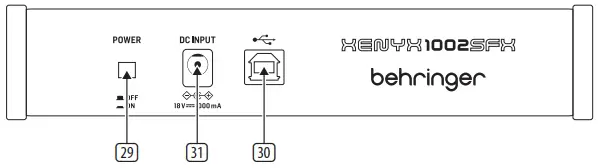
- POWER – Turns the unit on and off. Always make sure that power amps and speakers are turned down or OFF before switching the mixer ON or OFF.
- USB CONNECTOR – Connect your mixer to a computer using a standard USB cable.
- DC POWER IN – Only connect the supplied power supply.
Caution: The mixer cannot be bus-powered via USB. Always use the included power adapter to supply power to the mixer.
Presets List
| 00 | Small Chamber |
| 01 | Mid Chamber |
| 02 | Big Chamber |
| 03 | Theater |
| 04 | Small Room 1 |
| 05 | Small Room 2 |
| 06 | Mid Room 1 |
| 07 | Mid Room 2 |
| 08 | Large Room |
| 09 | Small Hall |
| 10 | Concert Hall |
| 11 | Mid Hall |
| 12 | Big Hall |
| 13 | Ambient Hall |
| 14 | Church |
| 15 | Short Plate |
| 16 | Mid Plate |
| 17 | Long Plate |
| 18 | Gold Plate |
| 19 | Vint250Verb 1 |
| 20 | Vint250Verb 2 |
| 21 | Mid Spring |
| 22 | Long Spring |
| 23 | Gated Reverb Short |
| 24 | Gated Reverb Mid |
| 25 | Gated Reverb Long |
| 26 | Gated Alive |
| 27 | Reverse Short |
| 28 | Reverse Mid |
| 29 | Reverse Long |
| 30 | Short Ambience |
| 31 | Mid Ambience |
| 32 | Live Ambience |
| 33 | Big Ambience |
| 34 | Stadium |
| 35 | Early Reflections 1 |
| 36 | Early Reflections 2 |
| 37 | Early Reflections 3 |
| 38 | Early Reflections 4 |
| 39 | Slap Delay |
| 40 | Short Delay 1 |
| 41 | Short Delay 2 |
| 42 | Mid Delay 1 |
| 43 | Mid Delay 2 |
| 44 | Mid Delay 3 |
| 45 | Long Delay 1 |
| 46 | Long Delay 2 |
| 47 | Long Delay 3 |
| 48 | Stereo Delay |
| 49 | Ping-Pong Delay |
| 50 | Short Echo |
| 51 | Mid Echo 1 |
| 52 | Mid Echo 2 |
| 53 | Long Echo 1 |
| 54 | Long Echo 2 |
| 55 | Soft Chorus |
| 56 | Warm Chorus |
| 57 | Phat Chorus |
| 58 | Classic Flanger |
| 59 | Warm Flanger |
| 60 | Stereo Flanger | |
| 61 | Classic Phaser | |
| 62 | Warm Phaser | |
| 63 | Heavy Phaser | |
| 64 | Stereo Phaser | |
| 65 | Slow Tremolo | |
| 66 | Fast Tremolo | |
| 67 | Panner 1 | |
| 68 | Panner 2 | |
| 69 | Detune 1 | |
| 70 | Detune 2 | |
| 71 | Minor Third Up | |
| 72 | Major Third Up | |
| 73 | Fifth Up | |
| 74 | Fourth Down |
| 75 | Octave Down |
| 76 | Minor Chord |
| 77 | Major Chord |
| 78 | Jazzy |
| 79 | Delay + Chorus 1 |
| 80 | Delay + Chorus 2 |
| 81 | Delay + Chorus 3 |
| 82 | Delay + Flanger 1 |
| 83 | Delay + Flanger 2 |
| 84 | Delay + Pitch 1 |
| 85 | Delay + Pitch 2 |
| 86 | Delay + Reverb 1 |
| 87 | Delay + Reverb 2 |
| 88 | Delay + Reverb 3 |
| 89 | Chorus + Reverb 1 |
| 90 | Chorus + Reverb 2 |
| 91 | Flanger + Reverb 1 |
| 92 | Flanger + Reverb 2 |
| 93 | Detune + Reverb |

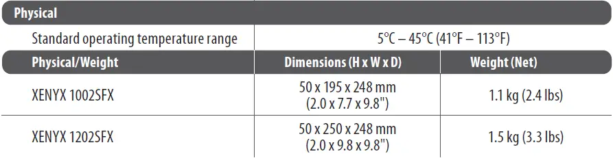
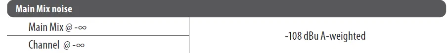
Specifications
| Microphone Input | Balanced XLR, discrete input circuit |
| Mic EIN (22 Hz-22 kHz) @ 50 Ω | 132 dB, A-weighted |
| Frequency response Gain +10 dB | 10 Hz to 150 kHz |
| Frequency response Gain +60 dB | 20 Hz to 70 kHz |
| Gain range | +10 dB to +60 dB |
| Max input level @ +10 dB Gain | +12 dBu |
| Input Impedance | 2 kΩ balanced |
| Distortion (THD + N) 1 kHz | |
| @ +10 dB Gain | 0.005% |
| Mono Line Inputs | ¼” TRS connector balanced |
| Impedance | 22 kΩ Balanced, 10 kΩ unbalanced |
| Gain range | -10 dB to +40 dB |
| Max input level @ 0 dB Gain | +21 dBu |
| Stereo Line | ¼” TRS connector balanced |
| Frequency response | 20 Hz to 200 kHz |
| Impedance | 22 kΩ Balanced, 10 kΩ unbalanced |
| Max input level @ 0 dB Gain | +21 dBu |
| STREAM Inputs (Analog) | RCA connector unbalanced |
| Impedance | 10 kΩ unbalanced |
| Max input level | 10 dBu |
| Low | 80 Hz/±15 dB |
| Mid | 2.5 kHz/±15 dB |
| High | 12 kHz/±15 dB |
| Type | ¼” TRS connector impedance-balanced |
| Impedance | 120 Ω |
| Max output level | 21 dBu |
| Type | ¼” TRS connector unbalanced |
| Impedance | 23 Ω |
| Max output level | 19 dBu/150 Ω |
| Type | RCA connector unbalanced |
| Impedance | 1 kΩ unbalanced |
| Max output level | 10 dBu |

| Type | Klark Teknik |
| Converter | 24-bit Sigma Delta |
| Sample Rate | 40 kHz |
| Type | Type-B connector |
| USB Audio Data | 48 kHz 16 Bit |
| UAC2 Class Compliant | stereo in/out |
| Power Consumption | 15 W |
| Adaptor input | 100 – 240 V~, 50/60 Hz, 0.5 A |
| Adaptor output | 18 V DC 1.0 A |

Other important information
- Register online: Please register your new Music Tribe equipment right after you purchase it by visiting musictribe.com. Registering your purchase using our simple online form helps us to process your repair claims more quickly and efficiently. Also, read the terms and conditions of our warranty, if applicable.
- Malfunction: Should your Music Tribe Authorized Reseller not be located in your vicinity, you may contact the Music Tribe Authorized Fulfiller for your country listed under “Support” at musictribe.com. Should your country not be listed, please check if your problem can be dealt with by our
“Online Support” which may also be found under “Support” at musictribe.com. Alternatively, please submit an online warranty claim at musictribe.com BEFORE returning the product. - Power Connections: Before plugging the unit into a power socket, please make sure you are using the correct mains voltage for your particular model. Faulty fuses must be replaced with fuses of the same type and rating without exception.
Responsible Party Name: Music Tribe Commercial NV Inc.
Address: 122 E. 42nd St.1, 8th Floor NY, NY 10168, United States
Email Address: [email protected]
XENYX 1002SFX / XENYX 1202SFX
This equipment has been tested and found to comply with the limits for a Class B digital device, pursuant to part 15 of the FCC Rules. These limits are designed to provide reasonable protection against harmful interference in a residential installation. This equipment generates, uses and can radiate radio frequency energy and, if not installed and used in accordance with the instructions, may cause harmful interference to radio communications. However, there is no guarantee that interference will not occur in a particular installation. If this equipment does cause harmful interference to radio or television reception, which can be determined by turning the equipment off and on, the user is encouraged to try to correct the interference by one or more of the following measures:
- Reorient or relocate the receiving antenna.
- Increase the separation between the equipment and receiver.
- Connect the equipment into an outlet on a circuit different from that to which the receiver is connected.
- Consult the dealer or an experienced radio/TV technician for help.
This equipment complies with Part 15 of the FCC rules. Operation is subject to the following two conditions:
- this device may not cause harmful interference,
- this device must accept any interference received, including interference that may cause undesired operation.
Important information
Changes or modifications to the equipment not expressly approved by Music Tribe can void the user’s authority to use the equipment.
Hereby, Music Tribe declares that this product is in compliance with Directive 2014/35/EU,Directive 2014/30/EU, Directive 2011/65/EU and Amendment 2015/863/EU, Directive 2012/19/EU, Regulation 519/2012 REACH SVHC and Directive 1907/2006/EC.
Full text of EU DoC is available at https://community.musictribe.com/
EU Representative: Music Tribe Brands DK A/S
Address: Gammel Strand 44, DK-1202 København K, Denmark
UK Representative: Music Tribe Brands UK Ltd.
Address: 6 Lloyds Avenue, Unit 4CL London EC3N 3AX,
United Kingdom
References
 Correct disposal of this product: This symbol indicates that this product must not be disposed of with household waste, according to the WEEE Directive