BATUR60.4 Sansui Batur Series Amplifiers Instruction Manual
INTRODUCTION
SYSTEM PLANNING
Proper system planning is the best way to maximize your amplifier performance.By planning your installation carefully you can avoid situations where the performance of the reliability of your system is compromised. Your authorized dealer has been trained to maximize your system’s sonic potential. Your dealer is a valuable resource in helping you with your system design and installation.
SPEAKER REQUIREMENTS
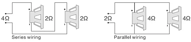
Each channel of your amplifier can easily drive 20 speaker loads when used in the stereo mode. When a channel-pair is bridged, the recommended minimum load impedance is 40 for subwoofer use, and 20 for full range operation.Although operation with lower impedances is not likely to cause immediate damage to the internal circuitry, the unit will most likely overheat, causing the thermal protection circuitry to shut down the amplifier. When the chassis cools down, normal operation will recume. Continuing to operate the amplifier under these conditions is not recommended and will reduce its life expectancy. Most speakers designed for car audio operation are 20 impedance. Connection two such speakers in parallel will result in a 20 impedance load as seen by the amplifier. Some subwoofer models feature a dual 40 voice coil design. Connecting these voice coils in parallel will result in a 20 nominal impedance, which is not recommended for use with bridged channels of your amplfier.
ACCESSORY LIST
- User Manual 1 pc
- Amplifier 1 pc
- M4.0x20 Tapping Screw 4 pcs
- Fuse(20A) 2 pcs
SPECIFICATIONS
| RMS Power Output @ 4 Ohm | 65W x 4 |
| RMS Power Output @ 2 Ohm | 100Wx 4 |
| Bridged Output @ 4 Ohm | 160W x 2 |
| T.H.D | <0.1% |
| Freqyency Response | 20Hz-22KHz |
| Signal To Noise Ratio | >90dB |
| Sensitivity | 0.30V-6.0V |
| Fuse Size | 20A x 2 |
| Unit Dimensions(L x H x W) | 340 x 190 x 46 mm |
| Net Weight | Approx. 1.95kg |
| Box Dimensions(L x H x W) | 400 x 214 x 65 mm |
| Gross Weignt | Approx. 2.35kg |
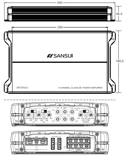
DIMENSIONS(UNIT:MM)
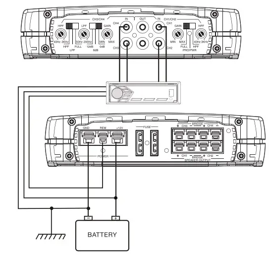
POWER CONNECTION LEADS
NOTES ON THE POWER SUPPLY
Connect the +12V power input lead only after all other leads have been connected. Be sure to connect the ground wire of the unit securely to a metal part of the car. A lose connection may cause a malfunction of the amplifier.
REMOTE: The unit is turned on by applying +12Volts to this terminal. This terminal dose not draw heavy current like the two power terminal so a thinner connecting wire is acceptable. Standard 18 GAUGE is fine and the standard colour is yellow. If the radio is equipped with a power antenna control wire, it can drive this terminal. If the power antrnna wire is already in use, you can still splice into it. With this method, the unit will turn on automatically with the radio. Use the power supply lead with a fuse attached whose value is the same as original fuse.
Place the fuse in the power supply lead as close as possible to the car battery. During a full power operation. Maximum current will run through the system. There-fore, Make sure that the leads to be connected to the +12V and GND terminals of the unit respectively must be larger than 8-Gauge (AWG.8).
System 1: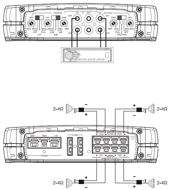
System 2: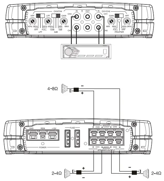
PANEL CONTROLS AND FEATURES
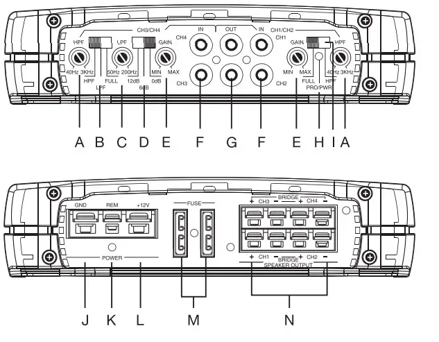
- A. CH3/CH4 SPEAKER HIGH PASS CROSSOVER FREQUENCY Controls high frequency of the amplifier between 120Hz to 3KHz.
- B. CH3/CH4 SPEAKER CROSSOVER CONTROL
Depending on the selected switch the amplifier will operate at full or hpf or 1pf mode. - C. CH3/CH4 SPEAKER LOW PASS CROSSOVER FREQUENCY Controls low frequency of the amplifier between 50Hz to 250Hz.
- D. BASS BOOST
The BASS BOOST feature will increase the sound level in the bass frequencies. - E. SPEAKER GAIN CONTROL
The gain control will match the amplifiers sensitivity to the source signal voltage. - F. LOW LEVEL RCA INPUT
These RCA inputjacks connect with your source unit RCA low level outputs or via optional adapter with your source unit speaker high level outputs. The use of high quality twisted pair car audio cables is recommended to reduce the possibility of audio signal degradation. - G. LOW LEVEL RCA OUTPUT
These RCA output jacks connect with your source unit RCA low level outputs or via optional adapter with your source unit speaker high level outputs. The use of high quality twisted pair car audio cables is recommended to reduce the possibility of audio signal degradation. - H. PROTECTION/POWER INDICATOR
The protection red LED will light up and flash if there is a fault present in the amplifier Please disconnect the amplifier and resolve the fault before reconnecting the amplifier. The power indicator green LED will light up when the amplifier is working correcly. - I. CH1 /CH2 SPEAKER CROSSOVER CONTROL
Depending on the selected switch the amplifier will operate at full or hpf mode. - J. GND(-) = GROUND CONNECTION
Connect this cable directly to the metal frame of the vehicle, ensuring that the metal frame has been stopped of all paint down to the bare metal use the shortest distance possible.lt is always a good idea to replace the vehicle battery groudon terminal or any other factory ground points. - K. REM(ON/OFF) REMOTE CONTROL
When using HI-INPUT, the amplifier can detect the DC offset from the high level input signal to automatically turn the amplifier on or off. When the amplifier turns on, the REM terminal will output +12V DC to control the other devices to tum on or off. When using low level inputs, the amplifier REM-IN should be connected to the REM-OUT of the source unit. The source unit will control the amplifier to automatically turn on or off. - L. +12V =POWER SUPPLY
Connect this terminal through a fuse or circuit breaker to the positive terminal of the vehicle battery or the positive terminal of an isolated audio system battery. - M. FUSE
Do not use a fuse with a different value and never replace the fuse with a wire or coin. - N. SPEAKER CONNECTIONS
Connect your speakers and woofers to there terminals, ensuring proper polarity during connection. Never connect the speaker cables to the chassis ground.
TROUBLE CLEARING
| SYMPTOM | POSSIBLE CAUSE | ACTION TO TAKE |
| NO OUTPUT | Low or no remote turn-on input | Check remote turn-on voltage output at amplifier and correct as needed |
| Fuse blown | Check power wire integrity and reversed polarity, repair as needed and replace fuse | |
| Power wires not connected | Check power wire and ground connections and repair or replace as needed | |
| Audio input not connected or no output from source | Check input connections and signal integrity, repair or replace as needed check speaker wires and repair or replace as needed | |
| AUDIO CYCLES ON AND OFF | Speakers are blown | Check system with known working speaker and repair or replace speakers as needed |
| The normal protection engages when amplifier heatsink temperature exceeds 90°C | Make sure there is proper ventilation for amplifier and improve ventilation as needed | |
| Loose or poor audio input | Check input connections and repair or replace as needed | |
| DISTORTED OUTPUT | Amplifier level sensitivity set too high; exceeding maximum output capability of amplifier | Reset gain referring to the tuning section of the manual for detailed instructions |
| Impedance load to amplifier too low | Check speaker impedance load if below 20 stereo or 40 mono rewire speakers to achieve a higher impedance | |
| Shorted speaker wires | Check speaker wire connections and repair or replace as needed | |
| Speaker not connected to amplifier properly | Check speaker wiring and repair of replace as needed refer to the installation section of this manual for detailed instructions | |
| Lnternal crossover not set properly for speaker | Reset crossovers referring to configuration section of this manual | |
| DISTORTED OUTPUT | Speakers are blown | Check system with known working speakers and repair or replace as needed |
| POOR BASS RESPONSE | Speakers wired wrong polarity causing cancellation as low frequencies | Check speaker polarity end repair as needed |
| Crossover set incorrectly | Reset crossovers referring to the multi-cross crossover configuration section of this manual for detailed instructions | |
| BATTERY FUSE BLOWING | Lmpedance load to amplifier too low | Check speaker impedance load.if below 211 stereo or 40 mono rewire speakers to achieve a higher Impedance |
| Short In power wire or incorrect power connections | Check power and ground connections and repair as needed | |
| Fuse used is smaller than recommended | Replace with proper fuse size | |
| Too much current being drawn | Check speaker impedance load, if below 20 stereo or 40 mono rewire speakers to achieve a higher impedance | |
| Short in power wire or incorrect | Check power and ground connections and repair as needed | |
| AMPLIFIER FUSE BLOWING | Too much current being drawn | Check speaker impedance load, if below 20 stereo or 40 mono rewire speakers to achieve a higher impedance and replace with recommended fuse sizeCheck power and ground connections and repair as needed |
| Fuse used is smaller than recommended | Replace with proper fuse size | |
| Lnternal crossover not set properly for speaker | Reset crossovers referring to configuration section of this manual |
SCAN OUR OR CODE OR VISIT WWW.SANSUICARAUDIO.COM GET MORE PRODUCT INFORMATIONS MADE IN CHINA I *Mil