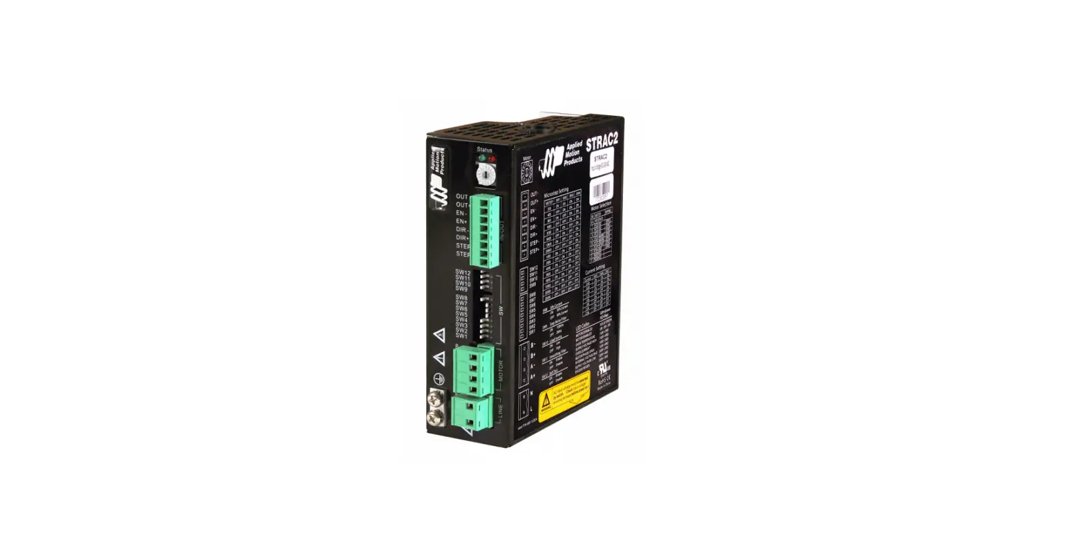
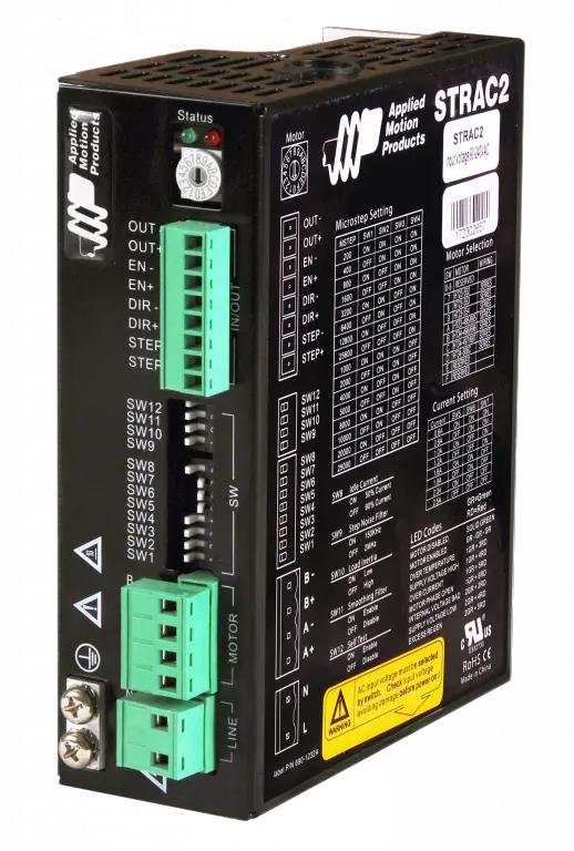
Applied Motion Products STRAC2 Stepper Drives
Requirements
To begin, make sure you have the following equipment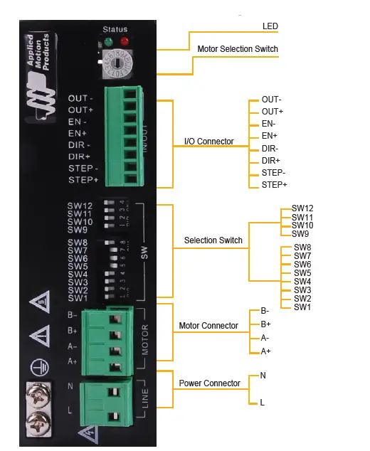
- A compatible stepper motor. Visit applied-motion.com to purchase one.
- A small flat blade screwdriver for tightening the connectors (included).
- An AC supply voltage, 90VAC-240VAC single-phase.
- A source of pulse & direction signals
INSTALLATION STEPS
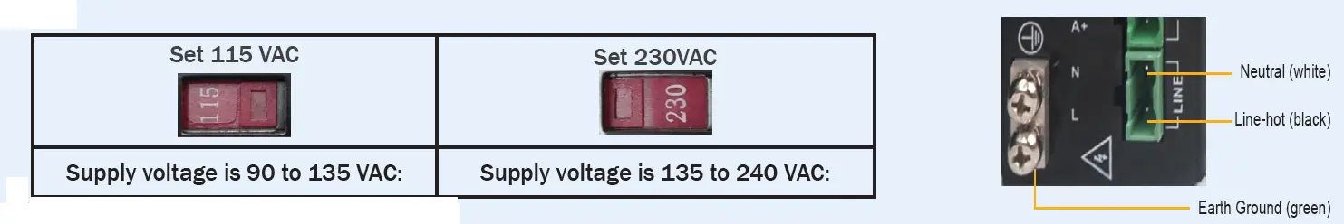
Step 1 -Wiring AC Power Supply
DO NOT apply power until all connections to the drive have been made
- Select Power input voltage AC input voltage must be selected by switch. Check input voltage to avoid damage before powering ON

- Wire the drive to the AC power source. Use the connector supplied with the drive and one of the ground terminals on the drive to connect the AC supply according to the
diagram to the right.
Use 16 AWG wire for Line (L) and Neutral (N). Use 14 AWG for Earth Ground (G)
Step 2 – Wiring the Motor
Connect the drive to the motor.
If using a non Applied Motion Products’ motor, consult the motor specs for wiring information.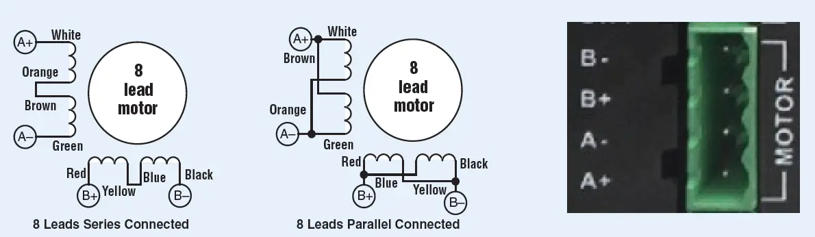
Step 3 – Select the Motor
Each position of the 16-bit rotary switch selects a different motor, automatically setting the configuration parameters in the drive. The STRAC2 drive comes programmed with up to 16 typical motors as factory defaults. Drives can be customized with specially selected motors when required. Available options are in the hardware manual.
If the motor selection is changed, the drive power supply will need to be cycled. For a custom motor, please select custom motor via the rotary switch, then use the DIP switches to configure motor current , anti-resonance and other settings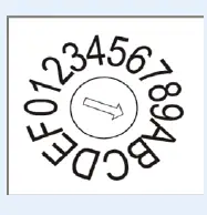
Step 4 – Config the Drive
Many operational parameters of the STRAC2 can be set or changed by DIP switches – either by a single switch or a combination of ON/OFF settings of 2 or more switches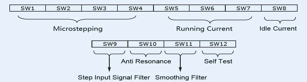
- Microstepping – 4 switches for a total of 16 setting
Microsteps(step/rev) SW1 SW2 SW3 SW4 200 ON ON ON ON 400 OFF ON ON ON 800 ON OFF ON ON 1600 OFF OFF ON ON 3200 ON ON OFF ON 6400 OFF ON OFF ON 12800 ON OFF OFF ON 25600 OFF OFF OFF ON 1000 ON ON ON OFF 2000 OFF ON ON OFF 4000 ON OFF ON OFF 5000 OFF OFF ON OFF 8000 ON ON OFF OFF 10000 OFF ON OFF OFF 20000 ON OFF OFF OFF 25000 OFF OFF OFF OFF - Idle Current(SW8) – 1 switches for a total of 2settings:
Idle SW8 50% ON 90% OFF - Step Input Signal Filter (SW9) – ON for 150 kHz, OFF for 2 MHz
- Running current – 3 switches for a total of 8 settings
Current(Peak) SW5 SW6 SW7 0.6A ON ON ON 0.8A OFF ON ON 1.0A ON OFF ON 1.2A OFF OFF ON 1.6A ON ON OFF 1.8A OFF ON OFF 2.0A ON OFF OFF 2.5A OFF OFF OFF - Anti-Resonance(SW10) – 1 switch for a total of 2 settings:
Option SW10 Inertia 0 ON Low 1 OFF High - Step Smoothing Filter (SW11) – ON to enable, OFF to disable
Step 5 – Self Test
The STRAC2 has a built in Self Test function. If switch 12 is moved to the ON position the drive will automatically rotate the motor back and forth, two turns in each direction. This feature can be used to confirm that the motor is correctly wired, selected and otherwise operational.
A full user manual for the STRAC2 is available for download from our website. This contains full details on setup, wiring and installation
If you have any questions or comments, please call Applied Motion Products Customer Support: (800) 525-1609, or visit us online: applied-motion.com
18645 Madrone Pkwy Morgan Hill, CA 95037
Tel: 800-525-1609
applied-motion.com
920-0121 Rev C


