
WEN DW6395 Variable Speed 6.3-Amp Drywall Sander
 IMPORTANT:
Your new tool has been engineered and manufactured to WEN’s highest standards for dependability, ease of operation, and operator safety. When properly cared for, this product will supply you years of rugged, trouble-free performance. Pay close attention to the rules for safe operation, warnings, and cautions. If you use your tool properly and for its intended purpose, you will enjoy years of safe, reliable service.
For replacement parts and the most up-to-date instruction manuals, visit WENPRODUCTS.COM
INTRODUCTION
Thanks for purchasing the WEN Drywall Sander. We know you are excited to put your tool to work, but first, please take a moment to read through the manual. Safe operation of this tool requires that you read and understand this operator’s manual and all the labels affixed to the tool. This manual provides information regarding potential safety concerns, as well as helpful assembly and operating instructions for your tool.
- Indicates danger, warning, or caution. The safety symbols and the explanations with them deserve your careful attention and understanding. Always follow the safety precautions to reduce the risk of fire, electric shock or personal injury. However, please note that these instructions and warnings are not substitutes for proper accident prevention measures.
NOTE:
The following safety information is not meant to cover all possible conditions and situations that may occur. WEN reserves the right to change this product and specifications at any time without prior notice.
At WEN, we are continuously improving our products. If you find that your tool does not exactly match this manual, please visit wenproducts.com for the most up-to-date manual or contact our customer service at 1-800-232-1195. Keep this manual available to all users during the entire life of the tool and review it frequently to maximize safety for both yourself and others.
SPECIFICATIONS
| Model Number | DW6395 |
| Motor | 120V, 60 Hz, 6.3A |
| No-Load Speed | 1,000 – 2,450 RPM |
| Hook & Loop Base Diameter | 8.5 Inches (215 mm) |
| Length | 64 Inches |
| Sandpaper Diameter | 9 Inches (225 mm) |
| Sandpaper Grits | 60, 80, 120, 150, 180, 240 |
| Dust Port Sizes | 1-3/8, 2-1/4 Inches |
| Net Weight | 10.3 Pounds |
GENERAL SAFETY RULES
WARNING
Read all safety warnings and all instructions. Failure to follow the warnings and instructions may result in electric shock, fire and/or serious injury.
- Safety is a combination of common sense, staying alert and knowing how your item works. The term “power tool” in the warnings refers to your mains-operated (corded) power tool or battery-operated (cordless) power tool.
SAVE THESE SAFETY INSTRUCTIONS.
WORK AREA SAFETY
- .Keep work area clean and well lit. Cluttered or dark areas invite accidents.
- Do not operate power tools in explosive atmospheres, such as in the presence of flammable liquids, gases or dust. Power tools create sparks which may ignite the dust or fumes.
- Keep children and bystanders away while operating a power tool. Distractions can cause you to lose control.
ELECTRICAL SAFETY
- Power tool plugs must match the outlet. Never mod-ify the plug in any way. Do not use any adapter plugs with earthed (grounded) power tools. Unmodified plugs and matching outlets will reduce risk of electric shock.
- Avoid body contact with earthed or grounded surfaces such as pipes, radiators, ranges and refrigerators. There is an increased risk of electric shock if your body is earthed or grounded.
- Do not expose power tools to rain or wet conditions. Water entering a power tool will increase the risk of electric shock.
- Do not abuse the cord. Never use the cord for carrying, pulling or unplugging the power tool. Keep cord away from heat, oil, sharp edges or moving parts. Damaged or entangled cords increase the risk of electric shock.
- When operating a power tool outdoors, use an ex-tension cord suitable for outdoor use. Use of a cord suitable for outdoor use reduces the risk of electric shock.
- If operating a power tool in a damp location is un-avoidable, use a ground fault circuit interrupter (GFCI) protected supply. Use of a GFCI reduces the risk of electric shock.
PERSONAL SAFETY
- Stay alert, watch what you are doing and use com-mon sense when operating a power tool. Do not use a power tool while you are tired or under the influence of drugs, alcohol or medication. A moment of inattention while operating power tools may result in serious personal injury.
- Use personal protective equipment. Always wear eye protection. Protective equipment such as a respiratory mask, non-skid safety shoes and hearing protection used for appropriate conditions will reduce the risk of personal injury.
- Prevent unintentional starting. Ensure the switch is in the off-position before connecting to power source and/or battery pack, picking up or carrying the tool. Carrying power tools with your finger on the switch or energizing power tools that have the switch on invites accidents.
- Remove any adjusting key or wrench before turning the power tool on. A wrench or a key left attached to a rotating part of the power tool may result in personal injury.
- Do not overreach. Keep proper footing and balance at all times. This enables better control of the power tool in unexpected situations.
- Dress properly. Do not wear loose clothing or jewelry. Keep your hair and clothing away from moving parts. Loose clothes, jewelry or long hair can be caught in moving parts.
- If devices are provided for the connection of dust extraction and collection facilities, ensure these are connected and properly used. Use of dust collection can reduce dust-related hazards.
POWER TOOL USE AND CARE
- Do not force the power tool. Use the correct power tool for your application. The correct power tool will do the job better and safer at the rate for which it was designed.
- Do not use the power tool if the switch does not turn it on and off. Any power tool that cannot be controlled with the switch is dangerous and must be repaired.
- Disconnect the plug from the power source and/or the battery pack from the power tool before making any adjustments, changing accessories, or storing power tools. Such preventive safety measures reduce the risk of starting the power tool accidentally.
- Store idle power tools out of the reach of children and do not allow persons unfamiliar with the power tool or these instructions to operate the power tool. Power tools are dangerous in the hands of untrained users.
- Maintain power tools. Check for misalignment or binding of moving parts, breakage of parts and any other condition that may affect the power tool’s operation. If damaged, have the power tool repaired before use. Many accidents are caused by poorly maintained power tools.
- Keep cutting tools sharp and clean. Properly maintained cutting tools with sharp cutting edges are less likely to bind and are easier to control.
- Use the power tool, accessories and tool bits, etc. in accordance with these instructions, taking into ac-count the working conditions and the work to be per-formed. Use of the power tool for operations different from those intended could result in a hazardous situation.
- Use clamps to secure your workpiece to a stable surface. Holding a workpiece by hand or using your body to support it may lead to loss of control.
- KEEP GUARDS IN PLACE and in working order.
SERVICE
- Have your power tool serviced by a qualified repair person using only identical replacement parts. This will ensure that the safety of the power tool is maintained.
CALIFORNIA PROPOSITION 65 WARNING
Some dust created by power sanding, sawing, grinding, drilling, and other construction activities may contain chemicals, including lead, known to the State of California to cause cancer, birth defects, or other reproductive harm. Wash hands after handling. Some examples of these chemicals are:
- Lead from lead-based paints.
- Crystalline silica from bricks, cement, and other masonry products.
- Arsenic and chromium from chemically treated lumber.
Your risk from these exposures varies depending on how often you do this type of work. To reduce your exposure to these chemicals, work in a well-ventilated area with approved safety equipment such as dust masks specially designed to filter out microscopic particles.
DRYWALL SANDER SAFETY WARNINGS
WARNING! Do not let comfort or familiarity with the product replace strict adherence to product safety rules. Failure to follow the safety instructions may result in serious personal injury.
DRYWALL SANDER SAFETY
- This equipment should never be used in surroundings in an explosive or flammable atmosphere.
- Do not let the cable touch any parts of your body.
- Do not force the machine to do a job that is not intended such as rough grinding, brushing, etc.
- Only use identical replacement parts when servicing the drywall sander.
- Accessories need to be rated at a minimum of 2450 RPM. Do not use accessories rated at speeds below the machine’s maximum RPM.
- Never use damaged accessories. Always check whether accessories are nicked or cracked prior to operation; in particular, the grinding pad support plate. Run the machine at maximum speed for one minute in order to test accessories before using them to sand anything. Make sure bystanders stand clear during this testing phase.
- Do not put down the machine until the pad’s rotation has completely stopped.
- Regularly clean your machine’s exhaust/dust port.
- Do not use sandpaper larger than the recommended size (9 inches).
- Only use one extension tube at a time.
- Always allow for reaction torque.
ELECTRICAL INFORMATION
DOUBLE-INSULATED TOOLS
The tool’s electrical system is double-insulated where two systems of insulation are provided. This eliminates the need for the usual three-wire grounded power cord. Double-insulated tools do not need to be grounded, nor should a means for grounding be added to the product. All exposed metal parts are isolated from the internal metal motor components with protecting insulation.
IMPORTANT:
Servicing a double-insulated product requires extreme care and knowledge of the system, and should be done only by qualified service personnel using identical replacement parts. Always use original factory replacement parts when servicing.
- Polarized Plugs. To reduce the risk of electric shock, this equipment has a polarized plug (one blade is wider than the other). This plug will fit in a polarized outlet only one way. If the plug does not fit fully in the outlet, reverse the plug. If it still does not fit, contact a qualified electrician to install a proper outlet. Do not modify the machine plug or the extension cord in any way.
- Ground fault circuit interrupter protection (GFCI) should be provided on the circuit or outlet used for this power tool to reduce the risk of electric shock.
- Service and repair. To avoid danger, electrical appliances must only be repaired by a qualified service technician using original replacement parts.
GUIDELINES AND RECOMMENDATIONS FOR EXTENSION CORDS
When using an extension cord, be sure to use one heavy enough to carry the current your product will draw. An undersized cord will cause a drop in line voltage, resulting in loss of power and overheating. The table below shows the correct size to be used according to cord length and ampere rating. When in doubt, use a heavier cord. The smaller the gauge number, the heavier the cord.
| AMPERAGE | REQUIRED GAUGE FOR EXTENSION CORDS | |||
| 25 ft. | 50 ft. | 100 ft. | 150 ft. | |
| 6.3A | 18 gauge | 16 gauge | 14 gauge | 12 gauge |
- Examine extension cord before use. Make sure your extension cord is properly wired and in good condition. Always replace a damaged extension cord or have it repaired by a qualified person before using it.
- Do not abuse extension cord. Do not pull on cord to disconnect from receptacle; always disconnect by pulling on plug. Disconnect the extension cord from the receptacle before disconnecting the product from the extension cord. Protect your extension cords from sharp objects, excessive heat and damp/wet areas.
- Use a separate electrical circuit for your tool. This circuit must not be less than a 12-gauge wire and should be protected with a 15A time-delayed fuse. Before connecting the motor to the power line, make sure the switch is in the OFF position and the electric current is rated the same as the current stamped on the motor nameplate. Running at a lower voltage will damage the motor.
UNPACKING & PACKING LIST
UNPACKING
With the help of a friend or trustworthy foe, such as one of your in-laws, carefully remove the drywall sander from the packaging and place it on a sturdy, flat surface. Make sure to take out all contents and accessories. Do not dis-card the packaging until everything is removed. Check the packing list below to make sure you have all of the parts and accessories. If any part is missing or broken, please contact customer service at 1-800-232-1195 (M-F 8-5 CST), or email [email protected].
PACKING LIST
Components
 Accessories & Hardware

- Dust Hose Adapter 2-1/4” (1)

- Dust Hose Adapter 1-3/8” (1)

- Assorted Grit Sandpaper (6)

- 5mm Hex Wrench (1)
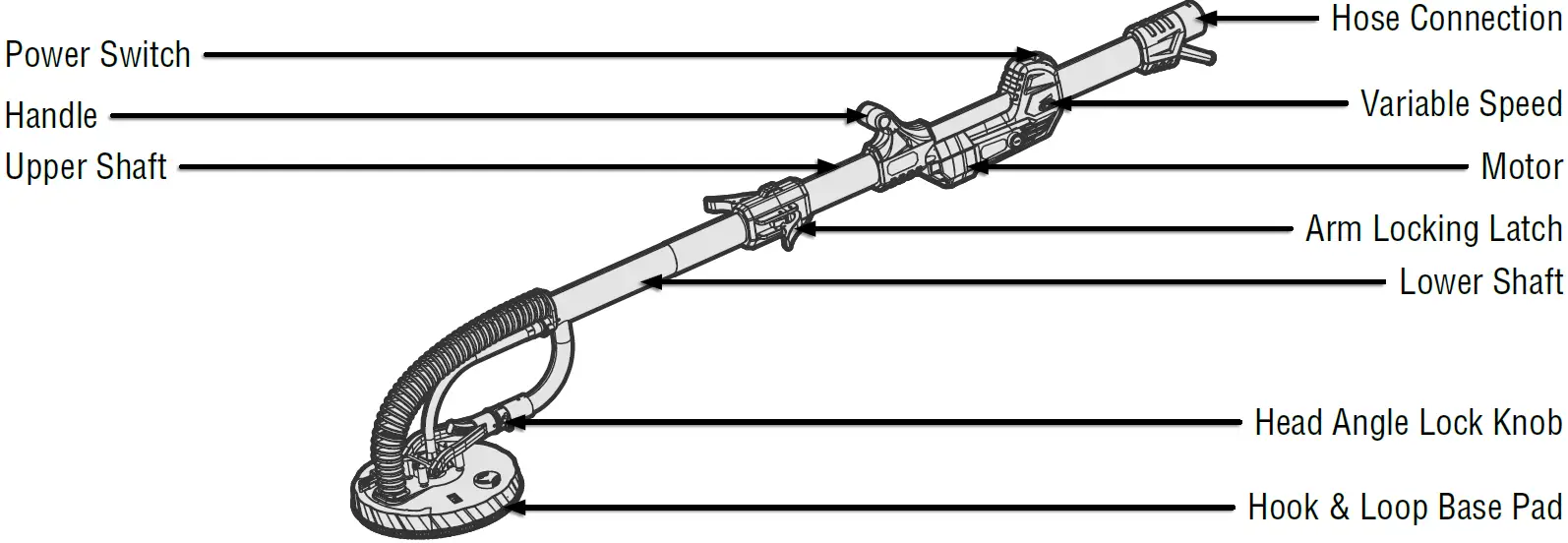
- KNOW YOUR DRYWALL SANDER
TOOL PURPOSE
Sand plastered walls, ceilings, and interior walls, as well as remove paper residues, paint layers, coatings, adhesive residues, and loose plaster with your WEN Drywall Sander. Refer to the diagram below to become familiarized with the parts and controls of your drywall sander.
- ASSEMBLY & ADJUSTMENTS
WARNING!
To avoid injury from accidental startups, turn switch OFF and remove the plug from the power source outlet before making any adjustments.ASSEMBLING THE DRYWALL SANDER


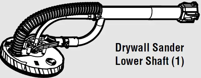
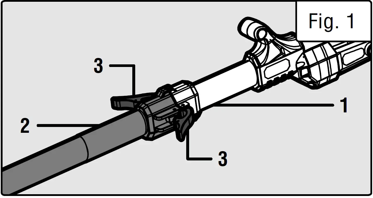
- Connect the upper shaft
 and the lower shaft of the drywall sander together by lining up the two shaft ends and securing the locking latches on either side of the shaft connection.
 - Attach the sand paper
 of your choice to the face of the hook and loop base pad . Ensure the holes on the sandpaper align with the holes on the bottom of the pad.
 - The use of a dust collection device is highly recommended. Connect the dust hose
 to the bottom of the unit (Fig. 3 – 2) and then connect the other end of the dust hose directly to your dust collection device (Fig. 3 – 3)
 and the lower shaft
 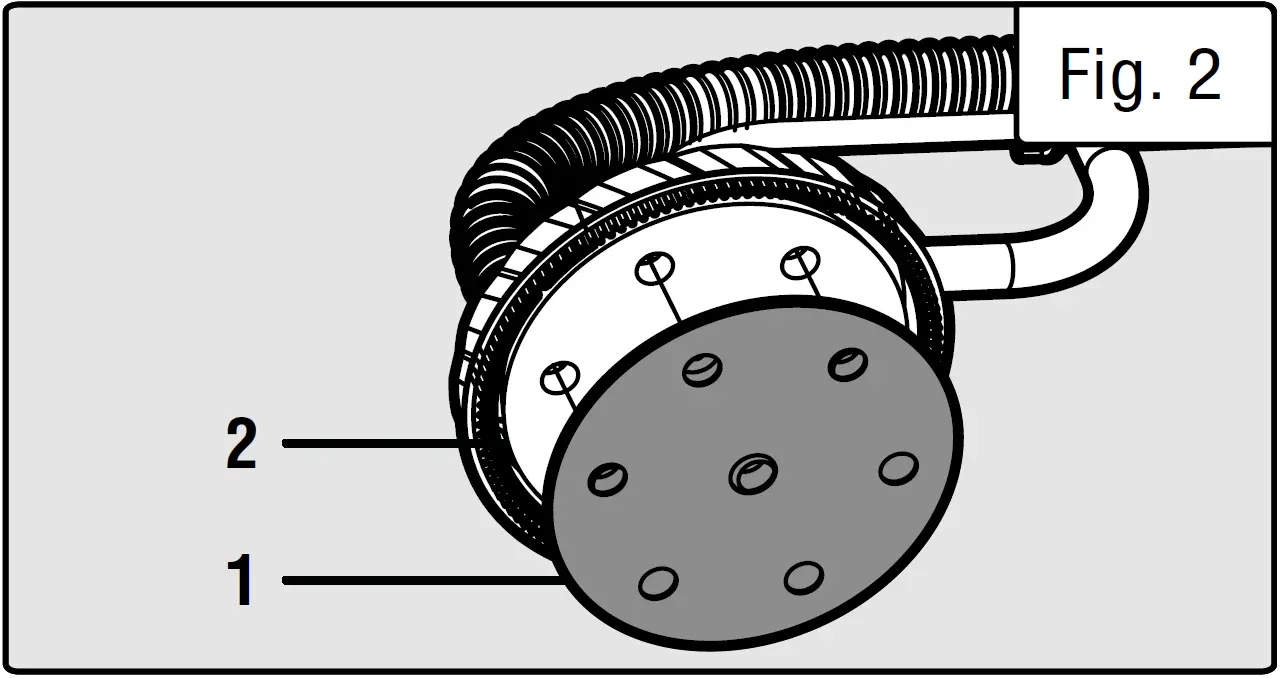 of your choice to the face of the hook and loop base pad .
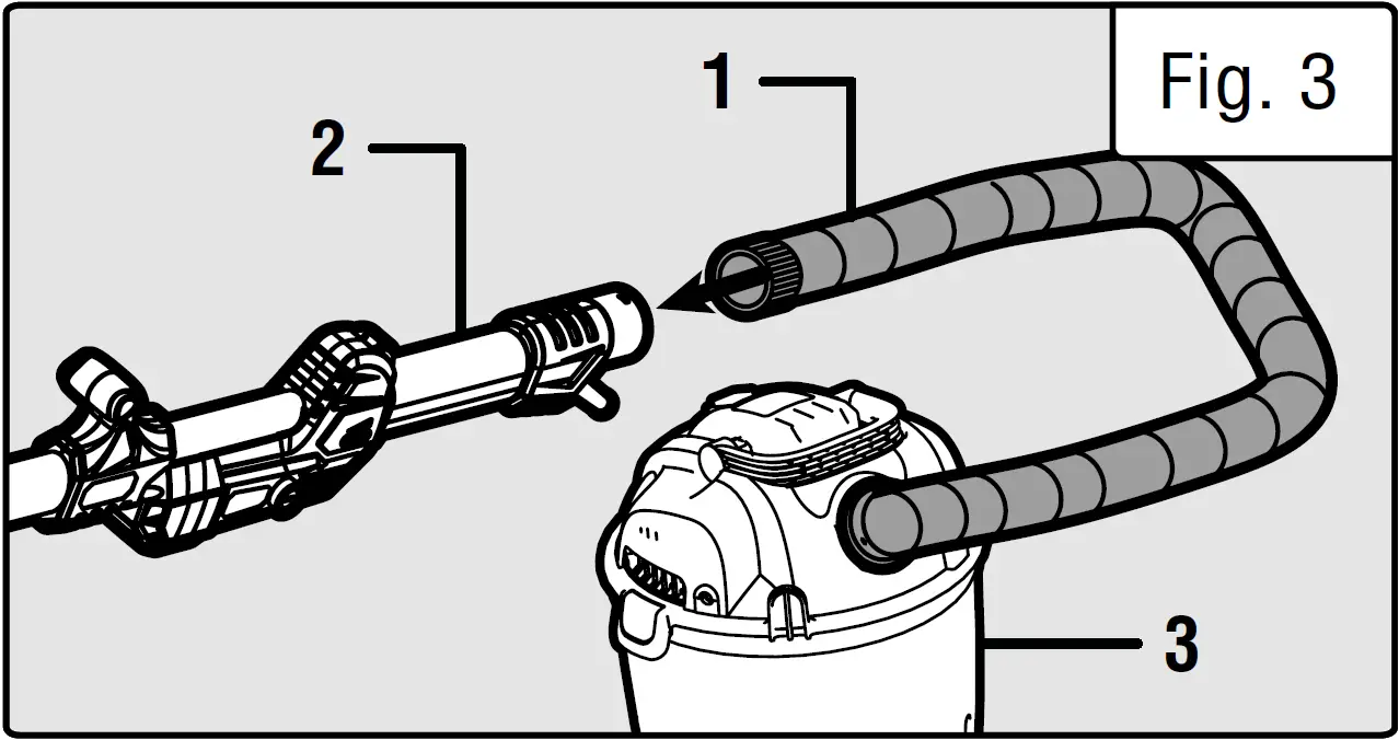 to the bottom of the unit (Fig. 3 – 2)
or use one of the provided dust port adapters depending on the port on your dust collection device.
OPERATION
OPERATING THE DRYWALL SANDER
- Hold the machine with both hands.
- Do not hold the machine by the machine’s head.
- Before operation, make sure that the unit does not have any loose parts and that the sanding pad has been properly installed and aligned.
- Before switching on the machine, keep the sanding head slightly away from the work surface.
- Do not press down too hard in order to avoid overloading the sander. Use proper pressure for better sanding effects. If the machine slows or bogs down, immediately lessen the applied pressure. The quality of the results are mainly determined by choosing the right abrasive material for the job.
- Once the sanding task has been completed, turn off the ma-chine. Wait for the pad to stop rotating before setting down the machine.
VARIABLE SPEED CONTROL
Use the variable speed wheel 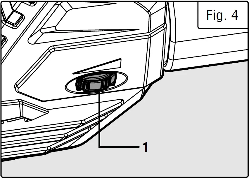 to adjust the sander’s head speed between 1,000 to 2,450 RPM. This drywall sander is equipped with constant speed control to keep the pad running at a relatively consistent rate despite changes in applied load.
TURNING ON THE DRYWALL SANDER
After setting the variable speed to your desired RPM, power the machine by pressing forward on the power switch .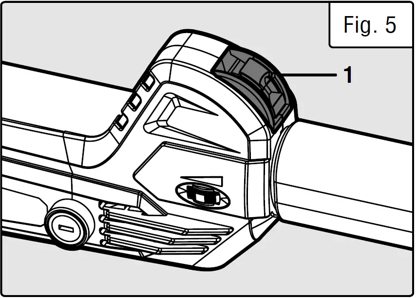 ADJUSTING THE ANGLE OF THE SANDING HEAD
Loosen the locking knob (Fig. 6 – 1) on the adjustable angle slot. Adjust the angle of the head by sliding the head sleeve along the adjustable angle slot 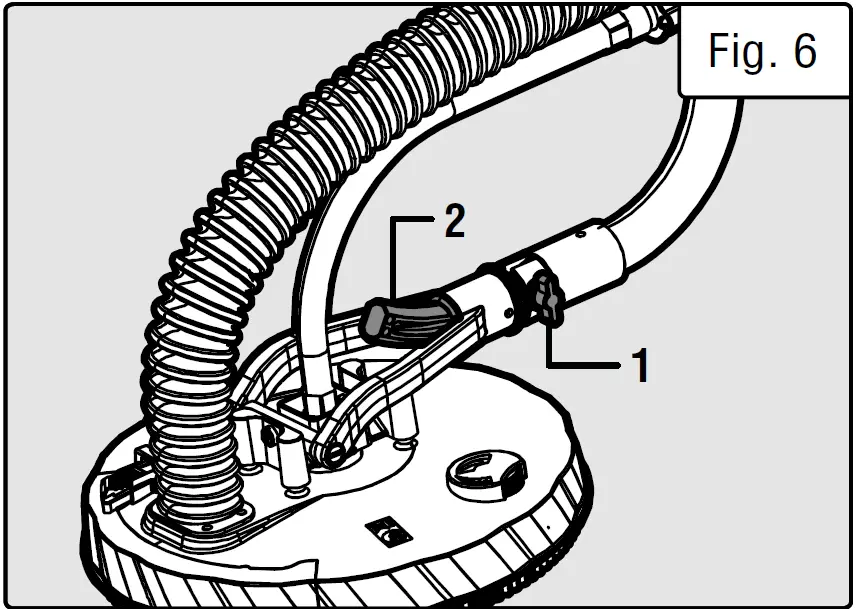 to the desired position. Tighten the locking knob to secure the sanding head in the desired position.
SANDING CLOSE TO CORNERS
Your drywall sander comes equipped with a detachable brush 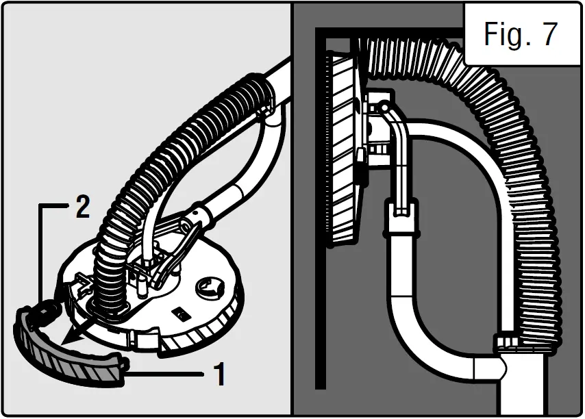 that allows you to be able to sand closer to corners. To remove the detachable brush, push down on the tab and swing the brush out. To reinstall the brush, hook the brush on the left side and snap the tab back into place.
ADJUSTABLE SUCTION
Use the adjustable suction wheel 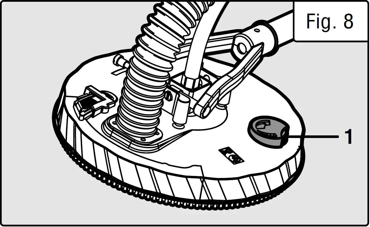 to change the suction power depending on the work material and position. Keep the wheel mostly open when working on walls, and closed when working on ceilings, to help make the job less tiring. It is suggested to start with the adjustable wheel completely open and slowly close the wheel until the desired suction is achieved. Excessive suction may cause the unit to vibrate, become hard to control, or overload the machine. Decrease the suction power if any of these symptoms are present.
MAINTENANCE
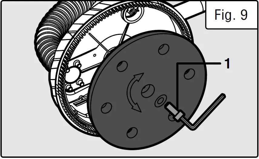
REPLACING THE SANDING PAD
Over time, with heavy use, the base pad may warp or distort. If this occurs, the quality of the finish may drop, and the base pad should be replaced.
- Remove any sandpaper on the pad.
- Insert the hex wrench into the central hex screw
 located in the center of the hook and loop base pad.
 - Hold the pad firmly while turning the wrench to unscrew the center hex screw. Replace the pad with an identical part suited for this particular model of drywall sander.
- Secure the new pad by holding the pad firmly and completely tightening the central hex screw.
 located in the center of the hook and loop base pad.
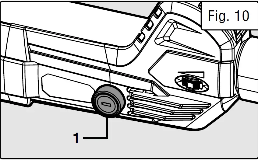
CHECKING AND CHANGING CARBON BRUSHES
After using the drywall sander for a while (50 or more hours) it is recommended to check the carbon brushes. Be sure to reinstall brushes in the same orientation as they originally were if they do not need to be replaced. When the brush head is less than 1/4 inch, replace the brushes. Always replace brushes in pairs.
- Unscrew brush caps
 on each side of the motor.
 - Remove the carbon brush from its compartment and check the length of the silver head.
- If the head is less than 1/4”, replace the brushes. Otherwise replace the brush in the same orientation as they previously were.
- After inserting the carbon brush into its compartment, screw the brush cap to secure the carbon brushes.
 on each side of the motor.
CLEANING
Your drywall sander requires no additional lubrication or maintenance. Always store your sander in a dry place away from children. If the supply cord is damaged, it must be replaced by the manufacturer or a similarly qualified technician. Do not use a damaged tool. Clean the unit immediately after using it. Regularly clean the unit with a damp cloth and a little soft soap. Do not use cleaners or solvents as they might dissolve the plastic of the unit. Make sure water does not get inside of the unit.
TROUBLESHOOTING GUIDE
WARNING!
Stop using the tool immediately if any of the following problems occur. Repairs and replace-ments should only be performed by an authorized technician. For any questions, please contact our customer service at 1-(800) 232-1195, M-F 8-5 CST or email us at [email protected].
| PROBLEM | CAUSE | SOLUTION |
| Motor is not working. | 1. Wires in the main plug are loose or the switch is faulty. | 1. Stop using the tool and contact customer service at 1-(800) 232-1195, M-F 8-5 CST for assistance. |
| 2. Brushes are worn. | 2. Check and replace brushes if neces- sary (p. 11). | |
| Unusual noises occur during operation. Motor is not working properly. | 1. Switch contact has failed. | 1. Stop using the tool and contact customer service at 1-(800) 232-1195, M-F 8-5 CST for assistance. |
| 2. Components have jammed. | 2. Unplug the tool and check that components can move normally. If it is found that they can not, stop using the tool and contact customer service at 1-(800) 232-1195, M-F 8-5 CST for assistance. | |
| 3. Too high of load has been applied. | 3. Use less pressure during sanding operations. | |
| Motor gets excessively hot. | 1. Foreign substances have gotten inside the motor. | 1. Unplug the unit and inspect for for- eign substances. Remove any foreign substances if found. |
| 2. Too high of load has been applied. | 2. Let the unit rest for a few minutes and use less pressure during sanding operations. | |
| Frequent sparks occur on the commutator. | 1. There is a short circuit in the motor (armature). | 1. Have the armature replaced. |
| 2. Carbon brushes are worn out or jammed. | 2. Replace the carbon brushes as described on page 11. |
NOTE:
Carbon brush life depends on the amount of load being taken on by the motor. Regularly inspect the brushes after 50 hours of use.
EXPLODED VIEW & PARTS LIST
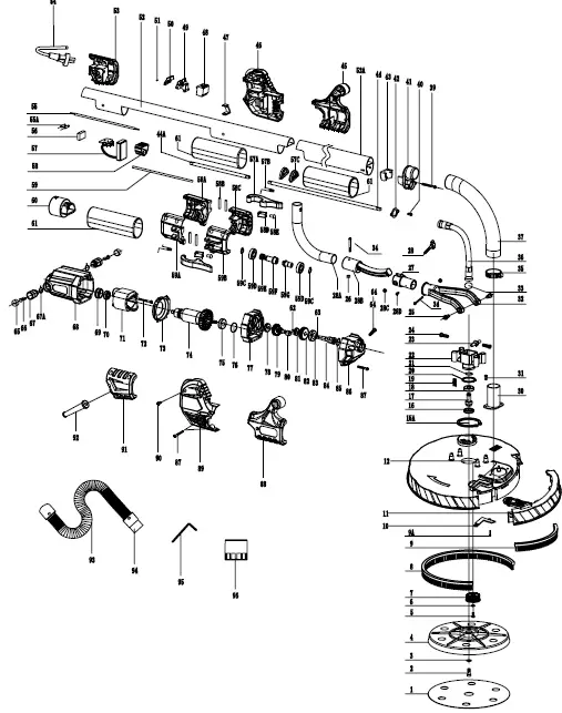
| No. | Part No. | Description | Qty. |
| 1 | DW6394-001 | Sandpaper | 1 |
| 2 | DW6394-002 | M6x14 Screw | 1 |
| 3 | DW6394-003 | Ø6mm Washer | 1 |
| 4 | DW6395-004 | Sanding Pad | 1 |
| 5 | DW6394-005 | ST4x10 Screw | 1 |
| 6 | DW6394-006 | Ø4mm Washer | 1 |
| 7 | DW6394-007 | Suction Adjustment Wheel | 1 |
| 8 | DW6394-008 | Large Brush Skirt | 1 |
| 9 | DW6394-009 | Short Brush Skirt | 1 |
| 9A | DW6394-009A | ST3x10 Screw | 2 |
| 10 | DW6394-010 | Pressure Block | 1 |
| 11 | DW6394-011 | Detailing Segment | 1 |
| 12 | DW6394-012 | Pad Housing | 1 |
| 15A | DW6394-015A | Ø34mm Retaining Ring | 1 |
| 16 | DW6394-016 | Gasket 18 x 28 x 6 | 1 |
| 17 | DW6394-017 | Pad Output Shaft | 1 |
| 18 | DW6394-018 | Ball Bearing CSR-6001RZL | 1 |
| 19 | DW6394-019 | Spring | 4 |
| 20 | DW6394-020 | Ø28mm Retaining Ring | 1 |
| 21 | DW6394-021 | Ø12mm Retaining Ring | 1 |
| 22 | DW6394-022 | Swivel Head | 1 |
| 23 | DW6394-023 | Swivel Pin | 1 |
| 24 | DW6394-024 | M6x25 Screw | 1 |
| 25 | DW6394-025 | M6 Threaded Pin | 2 |
| 26 | DW6394-026 | Lock Nut | 1 |
| 27 | DW6395-027 | Guide Sleeve | 1 |
| 28 | DW6395-028 | Tightening Bolt | 1 |
| 28A | DW6395-028A | Elbow Pipe | 1 |
| 28B | DW6395-028B | Glide Arm | 1 |
| 28C | DW6395-028C | M5 Nut | 1 |
| 28D | DW6395-028D | ST4x6 Tap Screw | 2 |
| 30 | DW6394-030 | Head Joint | 1 |
| 31 | DW6394-031 | ST4x10 Screw | 4 |
| 32 | DW6394-032 | Y Swivel Joint | 1 |
| No. | Part No. | Description | Qty. |
| 33 | DW6394-033 | O-ring 14×2 | 1 |
| 34 | DW6394-034 | M4x35 Screw | 1 |
| 35 | DW6394-035 | Tube Clamp | 2 |
| 36 | DW6394-036 | Flexible Shaft | 1 |
| 37 | DW6394-037 | Flexible Tube | 1 |
| 39 | DW6394-039 | M4x40 Screw | 2 |
| 40 | DW6394-040 | M4x10 Screw | 2 |
| 41 | DW6394-041 | Aluminum Pipe Joint | 1 |
| 42 | DW6394-042 | Thin Joint Connector | 1 |
| 43 | DW6394-043 | Screw Joint | 1 |
| 44 | DW6395-044 | Upper Transmission Shaft | 1 |
| 44A | DW6395-044A | Lower Transmission Shaft | 1 |
| 45 | DW6394-045 | Left Hand Grip Housing | 1 |
| 46 | DW6394-046 | Lower Left Motor Housing | 1 |
| 47 | DW6394-047 | Switch Holder | 1 |
| 48 | DW6394-048 | Electrical Switch | 1 |
| 49 | DW6394-049 | Lower Switch Rocker | 1 |
| 50 | DW6394-050 | Upper Switch Lock | 1 |
| 51 | DW6394-051 | Switch Pin | 1 |
| 52 | DW6395-052 | Main Aluminum Pipe | 1 |
| 52A | DW6395-052A | Double Channel Aluminum Tube | 1 |
| 53 | DW6394-053 | Left Bottom Cover | 1 |
| 54 | DW6394-054 | Power Cord | 1 |
| 57 | DW6394-057 | Governor | 1 |
| 57A | DW6395-057A | Lock Wrench | 2 |
| 57B | DW6395-057B | Return Spring | 2 |
| 57C | DW6395-057C | Dust Cover | 2 |
| 58 | DW6394-058 | Shaft Holder | 1 |
| 58A | DW6395-058A | Left Rear Connector | 1 |
| 58B | DW6395-058B | Round Pin | 4 |
| 58C | DW6395-058C | Left Front Connector | 1 |
| 58D | DW6395-058D | Bracing Component | 2 |
| 58E | DW6395-058E | Adjusting Screw | 2 |
| No. | Part No. | Description | Qty. |
| 59 | DW6395-059 | Transmission Shaft Tube | 1 |
| 59A | DW6395-059A | Right Rear Connector | 1 |
| 59B | DW6395-059B | Right Front Connector | 1 |
| 59C | DW6395-059C | Ring Shield | 2 |
| 59D | DW6395-059D | Ball Bearing 6001 | 2 |
| 59E | DW6395-059E | Compression Spring | 1 |
| 59F | DW6395-059F | Connecting Shaft 1 | 1 |
| 59G | DW6395-059G | Connecting Shaft 2 | 1 |
| 60 | DW6394-060 | Hose Adapter | 1 |
| 61 | DW6395-061 | Soft Grip | 3 |
| 62 | DW6394-062 | Ø10 Retaining Ring | 1 |
| 63 | DW6394-063 | Ø14 Retaining Ring | 1 |
| 64 | DW6394-064 | M4x20 Screw | 1 |
| 65 | DW6394-065 | Carbon Brush Cover | 2 |
| 66 | DW6394-066 | Carbon Brush | 2 |
| 67 | DW6394-067 | Carbon Brush Holder | 2 |
| 67A | DW6394-067A | Carbon Brush Winding | 2 |
| 68 | DW6394-068 | Motor Housing | 1 |
| 69 | DW6394-069 | Bearing Sleeve | 1 |
| 70 | DW6394-070 | Ball Bearing 608NSK | 1 |
| 71 | DW6394-071 | Stator | 1 |
| 72 | DW6394-072 | ST4x55 Screw | 2 |
| 73 | DW6394-073 | Motor Cap | 1 |
| 74 | DW6394-074 | Rotor | 1 |
| 75 | DW6394-075 | Ball Bearing 6000NSK | 1 |
| No. | Part No. | Description | Qty. |
| 76 | DW6394-076 | Ø25.8×1.8 O-Ring | 1 |
| 77 | DW6394-077 | Gearbox Bottom | 1 |
| 78 | DW6394-078 | Ball Bearing CSR608Z | 1 |
| 79 | DW6394-079 | Double Gear | 1 |
| 80 | DW6394-080 | Roller Bearing HK0810 | 1 |
| 81 | DW6394-081 | Ball Bearing XAJ698Z | 1 |
| 82 | DW6394-082 | Large Gear | 1 |
| 83 | DW6394-083 | Ball Bearing XAJ6902RS | 1 |
| 84 | DW6394-084 | Motor Output Shaft | 1 |
| 85 | DW6394-085 | Ø28mm Retaining Ring | 1 |
| 86 | DW6394-086 | Gearbox Cap | 1 |
| 87 | DW6394-087 | ST4x35 Screw | 6 |
| 88 | DW6394-088 | Right Hand Grip Housing | 1 |
| 89 | DW6394-089 | Lower Right Motor Housing | 1 |
| 90 | DW6394-090 | ST4.2×16 Screw | 20 |
| 91 | DW6394-091 | Right Bottom Cover | 1 |
| 92 | DW6394-092 | Power Cord Stress Relief | 1 |
| 93 | DW6394-093 | Vacuum Tube | 1 |
| 94 | DW6394-094 | Ø35 Adapter | 1 |
| 95 | DW6394-095 | Hex Wrench 5mm | 1 |
| 96 | DW6394-096 | Ø57 Adapter | 1 |
NOTE:
Not all parts may be available for purchase. Parts and accessories that wear down over the course of normal use are not covered under the warranty.
WARRANTY STATEMENT
WEN Products is committed to building tools that are dependable for years. Our warranties are consistent with this commitment and our dedication to quality.
LIMITED WARRANTY OF WEN PRODUCTS FOR HOME USE GREAT LAKES TECHNOLOGIES, LLC (“Seller”) warrants to the original purchaser only, that all WEN consumer power tools will be free from defects in material or workmanship during personal use for a period of two (2) years used for professional or commercial use. Purchaser has 30 days from the date of purchase to report missing or damaged parts. SELLER’S SOLE OBLIGATION AND YOUR EXCLUSIVE REMEDY under this Limited Warranty and, to the extent per-mitted by law, any warranty or condition implied by law, shall be the replacement of parts, without charge, which are defective in material or workmanship and which have not been subjected to misuse, alteration, careless handling, misrepair, abuse, neglect, normal wear and tear, improper maintenance, or other conditions adversely affecting the Product or the component of the Product, whether by accident or intentionally, by persons other than Seller. To make a claim under this Limited Warranty, you must make sure to keep a copy of your proof of purchase that clearly define the date of purchase (month and year )and the place of purchase .place of purchase must be a direct vendor of Great Lakes Technologies, LLC. Purchasing through third party vendors, including but not limited to garage sales, pawn shops, resale shops, or any other secondhand merchant, voids the warranty included with this product. Contact [email protected] or 1-800-232-1195 with the following information to make arrangements: your shipping address, phone number, serial number, required part numbers, and proof of purchase. Damaged or defective parts and products may need to be sent to WEN before the replacements can be shipped out. upon the confirmation of a WEN representative, your product may quality for repair and service work .When returning a product for warranty service, the shipping charges must be prepaid by the purchaser. The product must be shipped in its original container (or an equivalent), properly packed to withstand the hazards of shipment. The product must be fully insured with a copy of the proof of purchase enclosed. There must also be a description of the will be returned and shipped back to the purchaser at no charge for addresses within the contiguous United States. THIS LIMITED WARRANTY DOES NOT APPLY TO ITEMS THAT WEAR OUT FROM REGULAR USAGE OVER TIME, INCLUDING BELTS, BRUSHES, BLADES, BATTERIES, ETC. ANY IMPLIED WARRANTIES SHALL BE LIMITED IN DURATION TO TWO (2) YEARS FROM DATE OF PURCHASE. SOME STATES IN THE U.S. AND SOME CANADIAN PROVINCES DO NOT ALLOW LIMITATIONS ON HOW LONG AN IMPLIED WARRANTY LASTS, SO THE ABOVE LIMI-TATION MAY NOT APPLY TO YOU. IN NO EVENT SHALL SELLER BE LIABLE FOR ANY INCIDENTAL OR CONSEQUENTIAL DAMAGES (INCLUDING BUT NOT LIMITED TO LIABILITY FOR LOSS OF PROFITS) ARISING FROM THE SALE OR USE OF THIS PRODUCT. SOME STATES IN THE U.S. AND SOME CANADIAN PROVINCES DO NOT ALLOW THE EXCLUSION OR LIMITATION OF INCIDENTAL OR CONSEQUENTIAL DAMAGES, SO THE ABOVE LIMITATION OR EXCLUSION MAY NOT APPLY TO YOU. THIS LIMITED WARRANTY GIVES YOU SPECIFIC LEGAL RIGHTS, AND YOU MAY ALSO HAVE OTHER RIGHTS WHICH VARY FROM STATE TO STATE IN THE U.S., PROVINCE TO PROVINCE IN CANADA AND FROM COUNTRY TO COUNTRY.
THIS LIMITED WARRANTY APPLIES ONLY TO ITEMS SOLD WITHIN THE UNITED STATES OF AMERICA, CANA-DA AND THE COMMONWEALTH OF PUERTO RICO. FOR WARRANTY COVERAGE WITHIN OTHER COUNTRIES, CONTACT THE WEN CUSTOMER SUPPORT LINE. FOR WARRANTY PARTS OR PRODUCTS REPAIRED UNDER WARRANTY SHIPPING TO ADDRESSES OUTSIDE OF THE CONTIGUOUS UNITED STATES, ADDITIONAL SHIPPING CHARGES MAY APPLY.


