![]()
ADC-T2000
User Guide
Smart Thermostat
Product Manual
170308 v1.5
Smart Thermostat Product Manual

- Before installing or servicing the thermostat, turn off the power to the system at the circuit breaker.
- Leave the power off until you have finished installing or servicing.
- Shorting the electric terminals at the control on the heating or cooling system may damage the thermostat. Do not test the system this way.
- You must follow all local codes and ordinances for wiring the system.
- This thermostat should only be powered by 4 AA alkaline batteries or a listed class 2 power supply at 24 VAC (C-Wire or wall transformer).
- An amperage higher than 1 amp to each thermostat relay load may cause damage to the thermostat.
- Verify that the system is 24 VAC. If the old system is labeled as 120 or 240 volts or has wire nuts, the system is high voltage. Do not install the thermostat to a high voltage system. Contact a local HVAC professional for help.
BOX CONTENTS

RECOMMENDED TOOLS

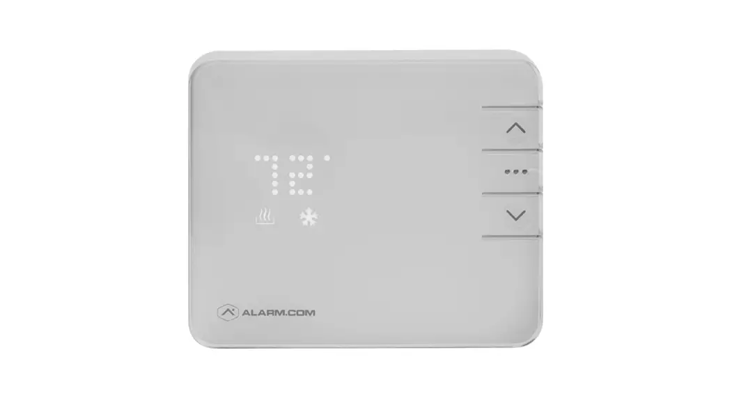
THERMOSTAT OVERVIEW

Buttons
- UP∧ – Adjust target temperature up.
- MODE… – Change thermostat between HEAT, COOL, AUTO, EMER, and OFF modes.
- DOWN∨ – Adjust target temperature down. Also used to include and exclude from the network.
Modes
- HEAT
 – Will activate the heating system.
 - COOL
 – Will activate the air conditioner.
 - AUTO
 – Will select either the HEAT or COOL mode automatically.
 - EMER – For use with heat pumps only. Will bypass the heat pump and enable the auxiliary/emergency heat.
- OFF – The system will not heat or cool.
Icons
- HEAT – Illuminated in HEAT, EMER, or AUTO mode.
- COOL – Illuminated in COOL or AUTO mode.
- RADIO
 – Illuminated during the wireless configuration.
LOCATION
If replacing an old thermostat, the new thermostat can be mounted in its place. If a new location is desired it will be necessary to move the wiring.
New installations and relocation should follow the accompanying guidelines to ensure the most accurate temperature reading and ease of use.
- Mount thermostat on an inside the wall, approximately 5 ft. (1.5m) above the floor in a frequently used room.
- Do not install in locations near appliances or devices that affect the local temperature such as televisions, lamps, or dryers.
- Avoid areas that are exposed to large temperature variances, such as direct sunlight, near an AC unit, above or below auxiliary heat and air vents, and drafts from windows.
- Be aware of what is on the other side of the wall where the thermostat is being installed. Do not install on walls adjacent to unheated rooms, stoves, or housing hot water pipes.
- Damp areas will not only affect the humidity reading of the thermostat but could lead to corrosion and shorten the life of the thermostat.
- Install in a location with good air circulation. Stagnant air will not accurately reflect the rate of temperature change in the room. Avoid areas behind
open doors, corners, and alcoves. - Wait until construction and painting are finished before installing.
PREPARATION
The Existing Thermostat
- Test the System
Verify that the heating and/or cooling system is operating properly before you try to install the new thermostat.
DO NOT test the system by shorting electric terminals at the furnace or air conditioner. This may damage the thermostat. - Turn Power Off
• Turn all heating and cooling systems off. This can be done at the circuit breaker.

CAUTION: DO NOT REMOVE the existing thermostat until power has been turned off at the circuit breaker.
Once the power to the heating AND cooling systems is off, follow these steps: - Remove Thermostat Cover
• Remove the cover from the existing thermostat.
Do not disconnect the wires yet.
TIP: Take a picture of the wires before you detach them from the existing thermostat for future reference. - Label All Existing Wires

• Label all existing wires, one at a time, with the labels provided.
Make sure the wires are labeled correctly. If you have an unidentified wire, it may be necessary to identify the wire where it connects to the heating or air conditioning equipment.
TIP: Take another picture of the wires to document connections for easy reference. Do not disconnect wires before labeling them.

![]()
CAUTION: Wiring can vary for each manufacturer. Label all wiring before removing it from the existing thermostat.
- Disconnect all of the wires and remove the existing thermostat.
TIP: Remember to secure the wires so they don’t fall into the wall.
Prepare the Wires
Follow these guidelines for safe and secure wire connections:
- Ensure the wires are a proper gauge between 18-24 AWG.
- Make sure wires have exposed straight ends about 1/8” long.
CAUTION: Verify that the system is 24 VAC. If the old system is labeled as 120 or 240 volts or has wire nuts, the system is high voltage. Do not install the thermostat to a high voltage system. Contact a local HVAC professional for help.
INSTALL YOUR NEW THERMOSTAT
Install the Back Plate
Use the bubble level provided on the backplate as a guide. Mark where the screws will go with a pencil through the screw holes on the backplate.
TIP: If necessary, use the trim plate to cover up any marks or holes left from the old thermostat. Attach the trim plate before securing the backplate to the wall.
TIP: Drill holes with a 3/16” drill bit to tap in the drywall anchors for added support.
Wire Your New Thermostat
Reconnect the wires to the new thermostat and indicate the connected wires with a pencil in the image below. This information will be needed when configuring the thermostat.

TIP: If you have extra wires do not install them in the new thermostat. Please contact your local HVAC professional for additional assistance.
- If you have R, connect it to RH.
- If you have RH & RC, remove the black jumper in the lower-left corner of the backplate terminal board with needlenose pliers.

- Z can be used for W3, H, DH, or O/B Zoning
Terminal Designations
| RC |
| RH Z |
| W |
| W2 |
| W3 C |
| Y Y2 |
| G |
| H DH |
| 0/B |
| awargaita Description Cooling bovver |
| Heating power |
| Configurable for W3, H, DH, or 0/B zoning |
| Heat stage 1 |
| Heat stage 2 |
| Heat stage 3 |
| The common wire from the secondary side of a cooling transformer (if 2 transformers) |
| Cool stage 1 |
| Cool stage 2 |
| Fan relay |
| Whole-home humidifier |
| Whole-home dehumidifier |
| HEAT PUMP |
| RC RH Z | Cooling power |
| Heating power | |
| Configurable for W3, H, or DH | |
| W | Aux stage 1 |
| W2 | Aux stage 2 |
| W3 | Aux stage 3 |
| C Y Y2 G H | A common wire from the secondary side of the cooling transformer |
| Pump stage 1 | |
| Pump stage 2 | |
| Fan relay | |
| Whole-home humidifier | |
| DH | Whole-home dehumidifier |
| 0/B | Reversing valve |
Insert Batteries Into the Thermostat

The thermostat can be powered by a battery or 24 VAC. If a wall transformer is used to power the thermostat, connect between C and RH.
Ensure the batteries are installed following the specified polarity markings on the thermostat.
CAUTION: Special Battery Warning
- Always replace the batteries as soon as you have low battery levels, indicated by “LOW” then “BATT” flashing on the display. If the batteries drain, the thermostat could leave the HVAC system on or off, overheating or freezing the home.
- Always replace the batteries at least once a year. This will protect the thermostat from damage and corrosion by leaking batteries.
- If the home is unoccupied for a month or more, such as vacation homes, you should replace the batteries as a preventive measure against battery failure while you are away.
- Always use new batteries as replacements.

Install Thermostat Body to Back Plate
Verify that any excess wire is tucked back into the wall to allow room for the thermostat to sit flush against the backplate.
Press the thermostat body firmly into the backplate mounted to the wall. Ensure that the pins on the body are correctly aligned with the header attached to the terminal board on the backplate. Failure to do so could cause damage to the thermostat.
Turn the Power On
Restore power to all the heating and cooling systems. This can be done at the circuit breaker.

Connect the Thermostat to the System

- Put the thermostat in OFF mode (No mode icons are lit).
- Put the Z-Wave controller into inclusion mode. Refer to the controller documentation for more information.
- Press and hold the DOWN∨ button on the thermostat to begin inclusion mode. Release the button when the RADIO icon lights up.
- When the RADIO icon becomes solid, the thermostat has been included.
- Log in to your online account (www.alarm.com/login) to sync the thermostat with the Alarm.com system, or contact an Alarm.com professional for installation setup.
Write your login information below once you have chosen a personal password.
| User ID: | |
| Password: |
CONFIGURE THE SYSTEM
The thermostat configuration will be done on your online account. Here you can configure the parameters of the system, such as Heat Pump or Normal, number of heat and cool stages, heating fuel, calibration temperature, and configurable terminal (Z). In your online account, you will have to enter the thermostat configuration. Refer to page 7 for the appropriate diagrams when you set up the thermostat.
While the default settings will be sufficient in most cases, you also have the option to change advanced configuration settings, such as SwingDifferential, Recovery Settings, Fan Circulation Period and Duty Cycle, Maximum Set Points, Minimum Set Points, and Thermostat Lock.
The thermostat can be configured locally for the most common configurations. Please see Page 12 for instructions.
WARNING: Use caution when changing advanced configuration settings. These configuration settings should only be changed by those familiar with heating and cooling systems’ parameters. Contact a local HVAC professional for help.
CHECK THE SYSTEM
WARNING: Do not test the AC during cold weather or heat during hot weather. Wait for mild weather to fully test the system.
To Check Heating
- Press the MODE … button to select HEAT mode.
- Press the UP ∧button to raise the setpoint above room temperature.
- Wait 5 minutes for the system to turn on.
- After verifying the heating system is working, return the setpoint to the desired temperature.
To Check Cooling
- Press the MODE button… to select COOL mode.
- Press the DOWN∨ button to lower the set the point below room temperature.
- Wait 5 minutes for the system to turn on.
- After verifying the cooling system is working, return the setpoint to the desired temperature.
Manual Configuration of HVAC System on Thermostat
- Put the thermostat in OFF mode.
- Press and hold the UP∧ button for 5 seconds until the display shows a version number.
- Press and hold the UP∧ button again for 5 seconds until the display shows your HVAC setup.
- Press the UP ∧or DOWN∨ buttons to select the thermostat configuration from the table below.
- Press the MODE… button to confirm your selection.
| Configuration | System Type | Description/Note |
| NORM
| Normal 2-heat 2-cool system
| Normal electric heating system, the thermostat turns on fan with heat. Two or fewer stages of heating and of cooling are allowed.
|
| FOSL
| Fossil 2-heat 2-cool system (for hydronic heat wino fan)
| Heat pump using 0 in the 0/B terminal with two or fewer stages of electric aux heating. |
| PUMP | Heat pump (0 terminal)
| Heat pump using 0 in the 0/B terminal with two or fewer stages of electric aux heating.
|
| PMPB | Heat pump (B terminal)
| Heat pump using B in the 0/B terminal with two or fewer stages of electric aux heating.
|
| DUAL | Dual fuel system (0 terminal) | Heat pump with two or fewer stages of fossil aux heating using 0 in the 0/B terminal. |
| DUMB | Dual fuel system (B terminal) | Heat pump with two or fewer stages of fossil aux heating using Bin the 0/B terminal |
OPERATION

- Press any button to wake the thermostat up.
- After waking, the display will show the current mode and room temperature.
- Press the UP∧ or DOWN∨ button once to display the current setpoint.
• The mode icon HEATor COOL will begin to pulse. - Press the UP∧ or DOWN ∨button again to adjust to the desired set point.
- Press the MODE …button at any time to change the mode.
- The modes are HEAT, COOL, AUTO, EMER, and OFF.
- EMER mode is available for Heat Pump systems. Press and hold the mode button while in Heat Mode to enter EMER.
- When in EMER mode, the display will read EMER when the thermostat wakes up and the HEAT icon will be displayed. Changing the mode will leave EMER mode.
- In AUTO, the brighter icon will indicate which setpoint is currently displayed and active HEAT or COOL
- After 5 seconds the display will return to the current room temperature. The mode icon will become solid to indicate this. If powered by the “C” wire, the thermostat display will remain lit. If the thermostat is running on battery power only, the display will turn off after 5 seconds to conserve energy. The thermostat will continue to operate while the display is off.
TROUBLESHOOTING
Heating or Cooling Doesn’t Turn On When the Set Point is Above or Below the Room Temperature
To prevent damaging the compressor, the thermostat inserts a delay when cycling the compressor. If you think the system should be on and it’s not, then change the setpoint to be 2 degrees beyond the current setpoint and wait 5 minutes to see if the system turns on. If not, contact a local HVAC professional.
Heat Pump is “Cooling When it Should be Heating” or “Heating When it Should be Cooling”
Because both types of heat pump reversing valves share a single terminal on your thermostat backplate, you need to be sure you have the thermostat configured for the correct wire. Try switching the O/B configuration setting through your online account. Contact a local HVAC professional for further help with this issue.
Exclude the Thermostat From the Z-Wave Network
If for some reason the thermostat must be excluded from the network, follow the steps below to do so.
- Set the thermostat to OFF mode.
- Press and hold the exclusion button on the Z-Wave controller. Refer to controller documentation for more information.
- Press and hold the DOWN∨ button on the thermostat to enter exclusion mode. Release the button when the RADIO icon lights up.
- When the RADIOicon flashes red, the thermostat has now been successfully excluded from the network.
Batteries Drain Quickly
If a thermostat is included using a “C” Wire, that information is saved in the network and cannot be changed unless excluded and included again without a “C” wire connected. The same applies to thermostats included on battery power.
If you find your thermostat batteries are draining unusually fast, make sure the “C”-Wire connection is still intact. If a device is included using the “C” Wire, the Z-Wave communication never sleeps, and the thermostat will act as a repeater, sending messages for other devices as well. If the “C” Wire is removed, this kind of activity will drain the battery very quickly.
For more help, contact your Alarm.com Service Provider.
NOTICES
FCC
This device complies with part 15 of the FCC Rules. Operation is subject to the following two conditions:
- This device may not cause harmful interference.
–and– - This device must accept any interference received, including interference that may cause undesired operation.
This equipment has been tested and found to comply with the limits for a Class B digital device, pursuant to part 15 of the FCC Rules. These limits are designed to provide reasonable protection against harmful interference in a residential installation. This equipment generates, uses, and can radiate radio frequency energy and, if not installed and used in accordance with the instructions, may cause harmful interference to radio communications. However, there is no guarantee that interference will not occur in a particular installation. If this equipment does cause harmful interference to radio or television reception, which can be determined by turning the equipment off and on, the user is encouraged to try to correct the interference by one or more of the following measures:
- Reorient or relocate the receiving antenna.
- Increase the separation between the equipment and receiver.
- Connect the equipment into an outlet on a circuit different from that to which the receiver is connected.
- Consult the dealer or an experienced radio/TV technician for help.
IC
Under Industry Canada regulations, this radio transmitter may only operate using an antenna of a type and maximum (or lesser) gain approved for the transmitter by Industry Canada. To reduce potential radio interference to other users, the antenna type and its gain should be so chosen that the equivalent isotropically radiated power (e.i.r.p.) is not more than that necessary for successful communication.
Note: The grantee is not responsible for any changes or modifications not expressly approved by the party responsible for compliance. Such modifications could void the user’s authority to operate the equipment.
![]() www.Alarm.com
www.Alarm.com
© 2017 Alarm.com. All rights reserved.
Documents / Resources
 | ALARM COM ADC-T2000 Smart Thermostat [pdf] User Manual ADC-T2000, Smart Thermostat |


")