![]() SPEAKER SYSTEM
SPEAKER SYSTEM
C112V/C115V/C215V/CM10V/CM12V/CM15V/C112VA/C115VA
SUBWOOFER
CW115V/CW118V/CW218V
Owner’s Manual
Thank you for choosing the YAMAHA speaker system. In order to take maximum advantage of the speaker’s features and ensure maximum performance and longevity, please read this manual carefully before using the speaker system. Keep the manual in a safe place for future reference.
PRECAUTIONS
PLEASE READ CAREFULLY BEFORE PROCEEDING
* Please keep this manual in a safe place for future reference.![]() WARNING
WARNING
Always follow the basic precautions listed below to avoid the possibility of serious injury or even death from electrical shock, short-circuiting, damages, fire, or other hazards. These precautions include, but are not limited to, the following:
Do not open
- Do not open the device or attempt to disassemble the internal parts or modify them in any way. The device contains no user-serviceable parts. If it should appear to be malfunctioning, discontinue use immediately and have it inspected by qualified Yamaha service personnel.
Water warning
- Do not expose the device to rain, use it near water or in damp or wet conditions, or place containers on it containing liquids that might spill into any openings.
![]() CAUTION
CAUTION
Always follow the basic precautions listed below to avoid the possibility of physical injury to you or others or damage to the device or other property. These precautions include, but are not limited to, the following:
Location
- If you use a stand, check the stand’s specifications and make sure that it is sturdy enough to support the weight of the speaker. You may need to limit the number of people around the placed stand, in order to avoid toppling the device or causing damage to the internal components.
- If you use speaker stands, be sure to keep the following cautions.
– Use the speaker stands with their legs fully opened.
– Mount only one speaker on each speaker stands.
– Tighten fastening screws securely.
– Remove the speakers from the stands before moving the stands or adjusting their height.
– Add weight such as sandbags around the stand legs to prevent them from falling over.
– Use the stand at a maximum height of 140cm (55″). - If you use a metal socket of the CW115V/CW118V subwoofer to allow mounting of a satellite speaker, use a pole shorter than 90cm (35.4″) with an outer diameter of 35mm (1-3/8″).
- When transporting or moving the device, always use two or more people.
- Before moving the device, remove all connected cables.
- Do not use the speaker’s handles for suspended installation. Doing so can result in damage or injury.
- Do not expose the device to excessive dust or vibrations, or extreme cold or heat (such as in direct sunlight, or near a heater) to prevent the possibility of panel disfiguration or damage to the internal components.
- Do not place the device in an unstable position where it might accidentally fall over.
Connections
- Before connecting the device to other devices, turn off the power for all devices. Before turning the power on or off for all devices, set all volume levels to a minimum.
- Use only speaker cables for connecting speakers to the speaker jacks. Use of other types of cables may result in fire.
- Be sure to observe the amplifier’s rated load impedance (see page 4), particularly when connecting speakers in parallel. Connecting an impedance load outside the amplifier’s
rated range can damage the amplifier.
Handling caution
- Always turn AC power to the power amplifier on last in any audio system to avoid speaker damage. When turning the power off, the power amplifier should be turned off first for the same reason.
- Do not use the device for a long period of time at a high or uncomfortable volume level, since this can cause permanent hearing loss. If you experience any hearing loss or
ringing in the ears, consult a physician. - Do not operate the device if the sound is distorting. Prolonged use in this condition could cause overheating and result in fire.
![]() This product, when used in combination with amplification and/or additional loudspeakers, may be capable of producing sound levels that could cause permanent hearing loss. DO NOT operate at high volume levels or at a level that is uncomfortable. If you experience any discomfort or ringing in the ears or suspect a hearing loss, you should consult an audiologist.
This product, when used in combination with amplification and/or additional loudspeakers, may be capable of producing sound levels that could cause permanent hearing loss. DO NOT operate at high volume levels or at a level that is uncomfortable. If you experience any discomfort or ringing in the ears or suspect a hearing loss, you should consult an audiologist.
To protect your speakers
When choosing a power amplifier to use with your speakers, make sure that its power output matches the speakers’ power capacity (refer to the Specifications on page 7). Even if the amplifier’s power output is lower than the speakers’ PGM (program) power capacity, the speakers may be damaged when clipping of a high input signal occurs. The following may cause damage to speakers:
- Feedback is caused when using a microphone.
- Continuous high sound pressure level produced by electronic instruments.
- Continuous high-power output distorted signals.
- Popping noises are caused by turning on equipment, or by connecting or disconnecting system components while the amplifier is turned on.
Poly Switch
All full-range loudspeakers are fitted with a self-resetting poly switch that protects the high-frequency driver from damage caused by excessive power.
If a loudspeaker cabinet loses high-frequency output, immediately remove power from the unit and wait for two to three minutes. They should allow the poly switch to reset. Reapply power and check the performance of the high-frequency driver before continuing with the power reduced to a level that does not cause the poly switch to interrupt the signal.
On the CW115V/CW118V/CW218V subwoofer, the Poly Switch protects the woofer and a similar routine should be followed if its output is lost.
- In any system using two or more speakers, be sure to match the connection polarities of all speakers to the amplifier(s) – e.g. always connect “+” to “+” and “-” to “-”. If the polarities are not properly matched the speakers will be driven out of phase and the sound will suffer.
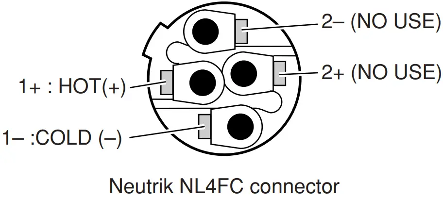
- Use only Neutrik NL4FC plugs for connecting Speakon connectors.
Yamaha cannot be held responsible for damage caused by improper use or modifications to the device.
* Illustrations in this manual are for explanatory purposes only, and may not match the actual appearance of the product during operation.
* Company names and product names used in this Owner’s Manual are trademarks or registered trademarks of their respective owners.
Connecting the Speakers
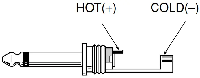
■ Phone Plug Wiring
Phone plugs for connection to the phone jack inputs should be wired as shown to the right. Be sure to use proper speaker cable — NOT shielded instrument or line cable — for all speaker connections.
■ Neutrik Speakon NL4FC Plug Wiring
If you will be using the Neutrik connectors for speaker input, wire the plugs as shown to the right. Be sure to use proper speaker cable — NOT shielded instrument or line cable — for all speaker connections.
■ Full-range Connection
Each speaker (except for the C112VA/ C115VA) features four input/parallel connectors—two 1/4” phone jacks and two Neutrik Speakon NL4MP connectors. Use either a phone jack or a Speakon connector to receive input from your sound system/power amplifier. One of the spare connectors can be used to parallel-connect an additional speaker (keeping in mind the impedance considerations mentioned below).
Impedance Considerations
When connecting speakers in parallel are sure to check the rated load impedance of the power amplifier. Most power amplifiers are capable of safely driving speakers with a minimum impedance of 8 ohms or 4 ohms. A pair of parallel-connected 8-ohm speakers have a total impedance of 4 ohms. Two 8-ohm speakers can safely be paralleled on one output. 4-ohm speakers, however, should not be parallel-connected with other speakers. These models can be connected in parallel, however, if you are using a power amplifier that can safely drive load impedances of 2 ohms or lower. Check your speaker impedance on page 7.
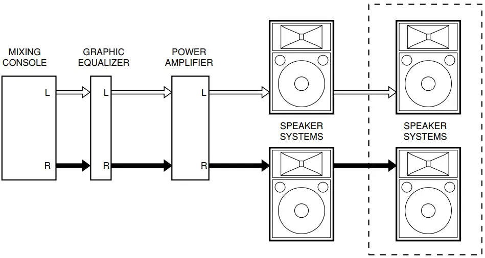
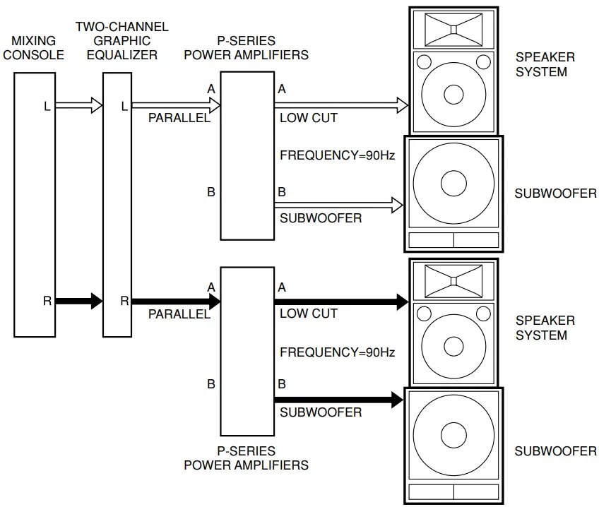
■ Subwoofers and the P-Series Power Amplifiers
Adding subwoofers to speaker systems like the one shown in the diagram can provide superior dynamic range and overall sound quality. After inputting the line-level audio from the preamplifier or mixing console into the Yamaha P-series power amplifiers (P7000S/P5000S/P3500S/P2500S), the separate frequency bands are outputted from the amplifiers.
Suspended and Bracket Installation
 Consult an installation expert to arrange for installation or construction work.
- Choose suspension wire, an installation location, and mounting hardware that are strong enough to support the weight of the speaker.
- Some fittings may deteriorate over extended periods of time due to wear or corrosion. For safety, the installation should be checked thoroughly at regular intervals.
Yamaha cannot be held responsible for damage or injury caused by insufficient strength of the support structure or improper installation.
■ Suspended Installation
The C112VA and C115VA can be used in suspended “flying” rigs by using an appropriate suspension wire.
- Replace the bolts with the supplied eyebolts (3/8″) as shown in the diagram, and then suspend the speaker using an appropriate wire.
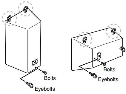
- Use only the supplied eyebolts.
- Use two or more eyebolts for suspended installation. Always use the eyebolts marked
 .
. - Do not suspend a speaker from another suspended speaker.
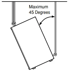
2. The speaker angle can be adjusted for optimum coverage by adjusting the lengths of the suspension wires, but the downward tilt angle must be less than 45 degrees, as shown in the diagram.
■ Bracket Installation
The C112VA has bracket-mounting screws on the top, bottom, and sides of the speaker enclosure. The C112VA can be mounted on a wall or ceiling using the optional brackets listed below.
| Bracket | Model |
| Wall bracket | BWS251-300, BWS251-400 |
| Ceiling bracket | BCS251 |
| Baton bracket | BBS251 |
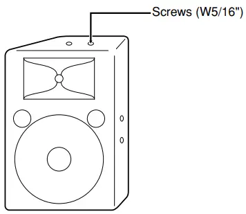
- Use only the specified screws (W5/16″) to attach the bracket to the speaker.
The mounting screws are installed on the speaker when it leaves the factory. Refer to the instruction manual supplied with your bracket for installation details.
Specifications
| Model | CM10V | C112V | C112VA | CM12V | C115V | C115VA | CM15V | C215V | |
| Enclosure | Bass Reflex Type | ||||||||
| Speaker Unit | LF | 10″ cone | 12″ cone | 15″ cone | 15″ cone ´ 2 | ||||
| HF | 1″ V.C.driver | 2″ V.C.driver | |||||||
| Frequency Response | 70Hz-20kHz | 60Hz-16kHz | 55Hz-16kHz | 42Hz-16kHz | |||||
| Power Capacity | NOISE* | 125W | 175W | 250W | 500W | ||||
| PGM | 250W | 350W | 500W | 1000W | |||||
| MAX | 500W | 700W | 1000W | 2000W | |||||
| Nominal Impedance | 8L | 4L | |||||||
| Sensitivity | 96dB SPL (1W, 1m) | 97dB SPL (1W, 1m) | 99dB SPL (1W, 1m) | 99dB SPL (1W, 1m) | |||||
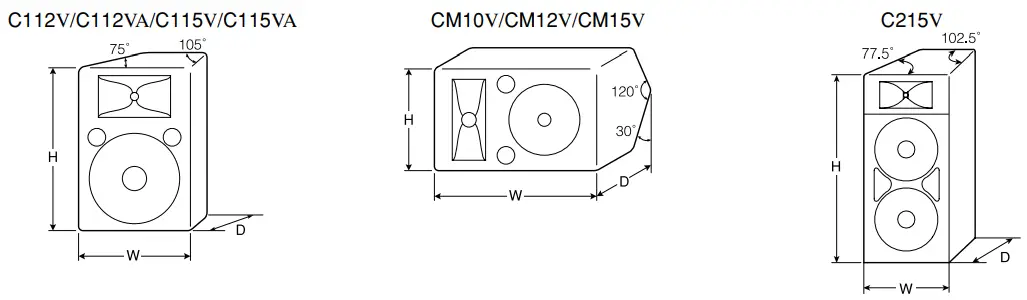
| Nominal Dispersion | Horizontal | 40˚ | 90˚ | 90˚ | 40˚ | 90˚ | 90˚ | 40˚ | 90˚ |
| Vertical | 60˚ | 40˚ | 40˚ | 90˚ | 40˚ | 40˚ | 90˚ | 40˚ | |
| Crossover Frequency | 1.8kHz | 2kHz | 1.7kHz | 1.5kHz | |||||
| Input Connectors | 1/4″ Phone Jack ´ 2, Neutrik Speakon NL4MP ´ 2 | Barrier Strip Terminal | 1/4″ Phone Jack ´ 2, Neutrik Speakon NL4MP ´ 2 | Barrier Strip Terminal | 1/4″ Phone Jack ´ 2, Neutrik Speakon NL4MP ´ 2 | ||||
| Dimensions (W ´ H ´ D) | 556 ´ 349 ´ 273mm | 416 ´ 628´ 329mm | 416 ´ 620´ 329mm | 628 ´ 410´ 339mm | 485 ´ 715´ 373mm | 485 ´ 707´ 373mm | 715 ´ 479´ 339mm | 491 ´ 1163´ 593mm | |
| Weight | 13.3Kg | 21.3Kg | 21.8Kg | 21.8Kg | 30.3Kg | 29.9Kg | 28.8Kg | 47.5Kg | |
| Included Accessories | — | — | Eyebolt (3/8″) ´ 4 | — | — | Eyebolt (3/8″) ´ 4 | — | — | |
| Model | CW115V | CW118V | CW218V | |
| Enclosure | Bass Reflex Type | |||
| Speaker Unit | 15″ cone | 18″ cone | 18″ cone ´ 2 | |
| Frequency Response | 35Hz-2kHz | 30Hz-2kHz | ||
| Power Capacity | NOISE* | 250W | 300W | 600W |
| PGM | 500W | 600W | 1200W | |
| MAX | 1000W | 1200W | 2400W | |
| Nominal Impedance | 8L | 4L | ||
| Sensitivity | 95dB SPL (1W, 1m) | 96dB SPL (1W, 1m) | 98dB SPL (1W, 1m) | |
| Recommended Crossover Frequency | 90Hz, 12dB/Oct. | |||
| Input Connectors | 1/4″ Phone Jack ´ 2, Neutrik Speakon NL4MP ´ 2 | |||
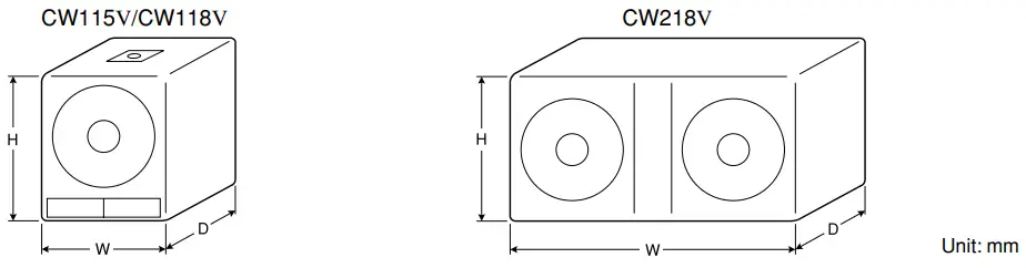
| Dimensions (W ´ H ´ D) | 500 ´ 607 ´ 528mm | 605 ´ 720 ´ 637mm | 1217 ´ 574 ´ 655mm | |
| Weight | 28Kg | 37.2Kg | 64.7Kg | |
Specifications and descriptions in this owner’s manual are for information purposes only. Yamaha Corp. reserves the right to change or modify products or specifications at any time without prior notice. Since specifications, equipment or options may not be the same in every locale, please check with your Yamaha dealer.
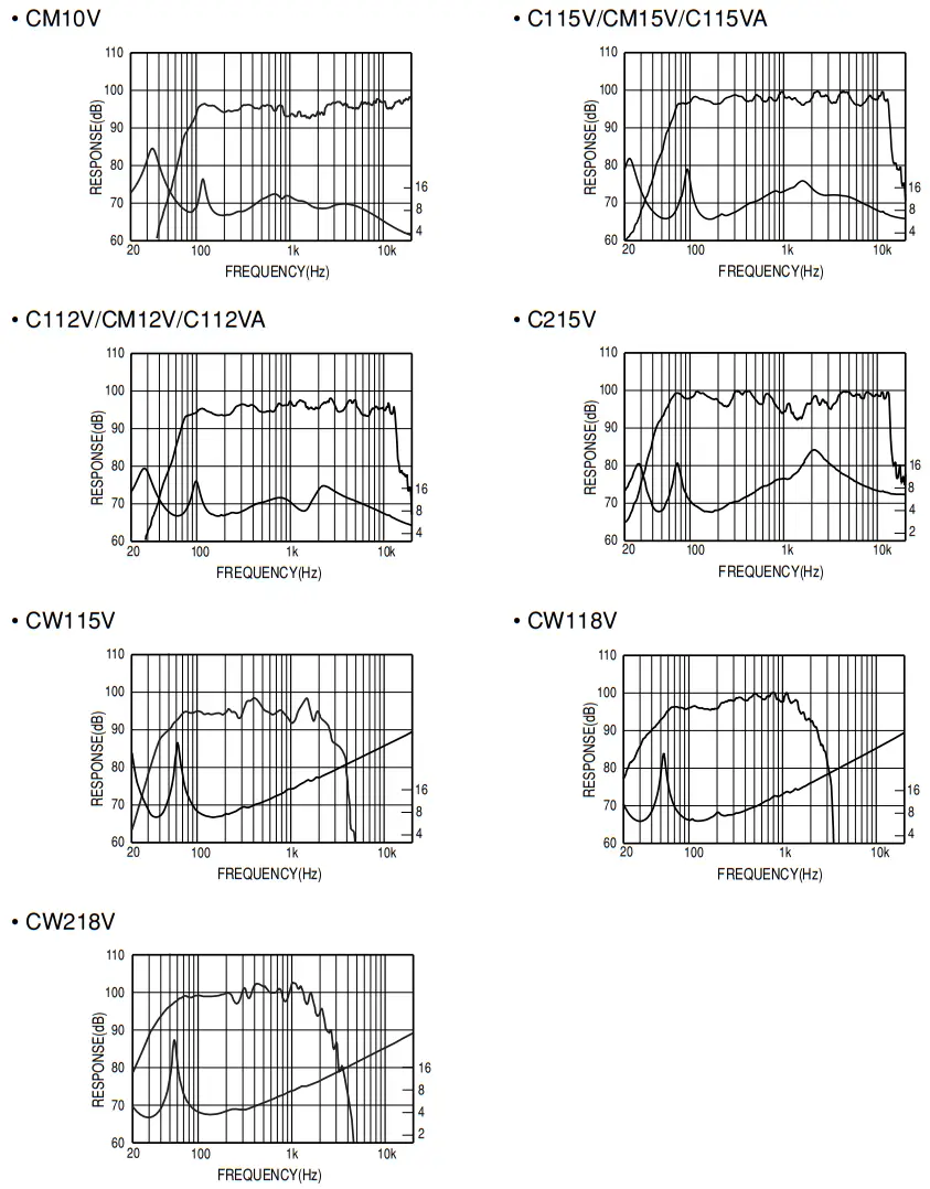
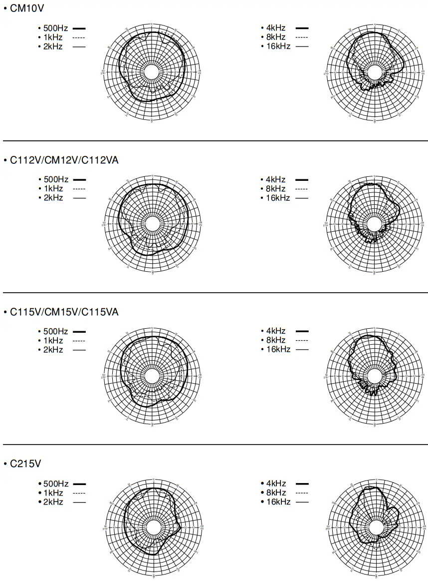
Technical Data
■ Frequency Response/Impedance
■ Horizontal Directivity
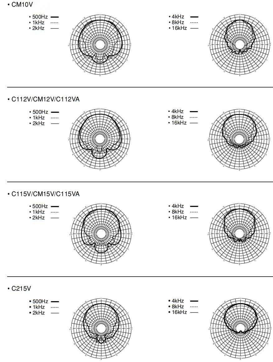
■ Vertical Directivity
For details of products, please contact your nearest Yamaha representative or the authorized distributor listed below.
| CANADA Yamaha Canada Music Ltd. 135 Milner Avenue, Scarborough, Ontario, M1S 3R1, Canada Tel: 416-298-1311 | The U.S.A. Yamaha Corporation of America 6600 Orangethorpe Ave., Buena Park, Calif. 90620, The U.S.A. Tel: 714-522-9011 |
| THE UNITED KINGDOM Yamaha Music U.K. Ltd. Sherbourne Drive, Tilbrook, Milton Keynes, MK7 8BL, England Tel: 01908-366700 | GERMANY Yamaha Music Central Europe GmbH Siemensstraße 22-34, 25462 Rellingen, Germany Tel: 04101-3030 |
HEAD OFFICE
Yamaha Corporation, Pro Audio & Digital Musical Instrument Division
Nakazawa-cho 10-1, Naka-ku, Hamamatsu, Japan 430-8650
Tel: +81-53-460-2441
Yamaha Pro Audio global website:
http://www.yamahaproaudio.com/
Yamaha Manual Library:
http://www.yamaha.co.jp/manual/
C.S.G.., Pro Audio Division
© 2003 Yamaha Corporation
WK60300 CR D0
PA19


