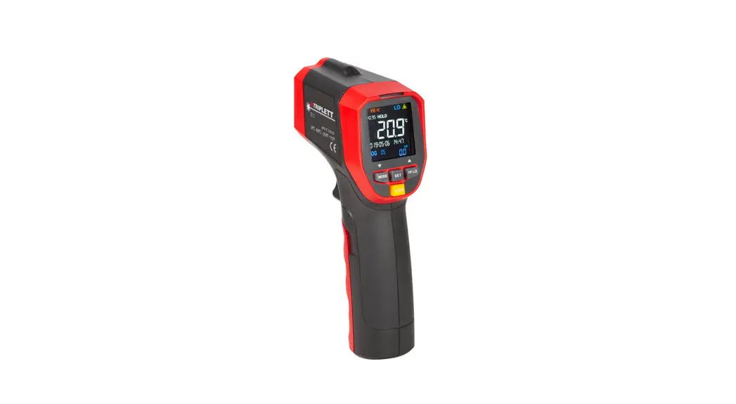
![]() IRTUV50 IR Thermometer with Built-in UV Refrigerant
IRTUV50 IR Thermometer with Built-in UV Refrigerant
Leak Detector and Flashlight
User Manual 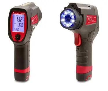
Introduction
Congratulations on your purchase of the Triplett IRTUV50
IR Thermometer with Built‐in UV Refrigerant Leak Detector and Flashlight This thermometer makes non‐contact (infrared) temperature measurements at the touch of a button. The built‐in coaxial laser pointer increases target accuracy while the backlit LCD and handy multi‐switch combine for convenient, ergonomic operation. The UV light source is convenient for locating leaks such as refrigerants
Features
- Measures non‐contact surface temperature up to 932°F ( 500°C )
- 12:1 Distance to Spot Ratio (Field of View)
- Precise non-contact measurements
- Multipoint laser sighting
- White LED built-in illuminators
- Blue LED built-in illuminators for UV function
- Unique flat surface, modern housing design
- Automatic Data Hold
- “MAX/MIN/AVG/DIFF” function
- Emissivity Digitally adjustable from 0.10 to 1.0
- Adjustable High and Low Alarms
Safety
International Safety Symbols![]() This symbol, adjacent to another symbol or terminal indicates the user must refer to the manual for further information
This symbol, adjacent to another symbol or terminal indicates the user must refer to the manual for further information 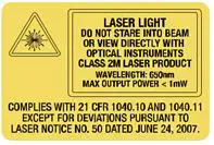
Warnings
- Do not directly or indirectly point the laser at the eyes of a person or an animal aspect for damage or for any shortage of parts or accessories before use
- Replace the batteries immediately after the battery indicator flashes o Do not use the thermometer near explosive gases, steam, or dust
- Note that an object with high reflectivity will normally cause the measured temperature value to read much lower than the actual temperature
- Use the device only as described in this User Guide
Cautions
- To avoid thermometer damage, please avoid the following hazards: EMF from welding equipment or electro‐ induction heaters o Static electricity
- The thermal shock is caused by large or abrupt environmental temperature changes; wait 30 minutes to allow the thermometer to stabilize to new environmental conditions
- Do not use this device in excessively high-temperature environments
Meter Description
METER DESCRIPTION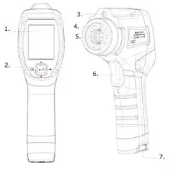
| 1. LCD Display | 5. IR Sensor |
| 2. MENU/MODE Button | 6. Power On/Measure Trigger |
| 3. Laser | 7. Battery Compartment |
| 4. UV LEDs |
DISPLAY LCD DESCRIPTION
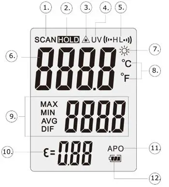
| 1. Scan Icon | 7. Work Light LED ON |
| 2. DATA HOLD | 8. °C/°F Icon |
| 3. Laser ON Indicator | 9. MAX/MIN/AVG/DIF Mode Indicator |
| 4. UV LED ON Indicator | 10. Emissivity |
| 5. HI and Low Alarm | 11. APO (Auto Power OFF) ON |
| 6. Measurement Data | 12. Battery Status |
Operation
Meter Power
The meter is powered by two 1.5V AA batteries. With fresh batteries installed, the meter switches ON when the trigger is pulled. Refer to the Maintenance section for Battery Installation instructions. The battery icon provides a battery status indication. Replace the batteries as soon as the battery status icon indicates a low battery.
Setting Mode
The various parameters of the meter are set using the five‐way multi‐switch located below the display. The available parameters are listed below:
Setting Mode Overview
The Settings switch has five positions to select a parameter, turn a parameter ON or OFF, and to adjust parameter values.
Press and release the Measurement Trigger.
Press the ![]() button left to enter the Setting Mode. The parameter selected will appear in the display.
button left to enter the Setting Mode. The parameter selected will appear in the display.
Press the ![]() button right to advance to the next parameter.
button right to advance to the next parameter.
Press the up![]() or down
or down ![]() buttons to change a parameter status or adjust a parameter value.
buttons to change a parameter status or adjust a parameter value.
Press the ![]() button to store parameter changes and advance to the next parameter.
button to store parameter changes and advance to the next parameter.
Press the ![]() button left to exit the Settings mode and return to Measurement mode.
button left to exit the Settings mode and return to Measurement mode.
Note: If no button is pressed within the APO time the meter will shut down. It may be helpful to extend the APO time when making adjustments in the Settings mode.
Setting Mode Detail
- Flashlight Setting
Enter the Setting mode. The Flashlight icon flashes. Press up
 for ON or OFF. Press
 to store the setting
 - UV light Setting
Enter the Setting mode. Advance until the UV icon flashes. Press up for ON or OFF. Press to store the setting - Temperature Units Setting
Enter the Setting mode. Advance until the °F or °C icon flashes. Press up to change the units. Press to store the setting - Emissivity Setting
Enter the Setting mode. Advance until the EMS icon flashes.
Press up or down to adjust the setting. Press to store the setting - Laser Pointer Setting
Enter the Setting mode. Advance until the icon flashes. Press up for ON or OFF. Press to store the setting
 - Max Min Avg Max‐Min Setting
Enter the Setting mode. Advance until the MAX – MIN AVG icon flashes. Pressup for ON or OFF. Press to store the setting - Alarm HI Setting
Enter the Setting mode. Advance until the Alarm HI icon flashes. Press up or down for ON or OFF. Press to store the setting If ON was selected, press up or down to adjust the limit. Press to store the setting - Alarm LO Setting
Enter the Setting mode. Advance until the Alarm LO icon flashes. Pressup or down for ON or OFF. Press to store the setting If ON was selected, Press up or down to adjust the limit. Press to store the setting - Backlight Setting
Enter the Setting mode. Advance until the LItE icon flashes. Pressup or down for ON or OFF. Press to store the setting - Auto Power OFF Setting
Enter the Setting mode. Advance until the APO icon flashes. Pressup or down to adjust the setting. Press to store the setting
Surface Temperature Measurements
- The typical settings should be: Laser pointer ON, Backlight ON, Temperature units set as needed, Emissivity set to 0.95, APO (auto power OFF) set to 10 seconds, and Flashlight ON if measuring in a dimly lit area.
- Open the lens protective lens cover by rotating the cover wheel clockwise (facing the lens) until the dot is visible on the wheel.
- Hold the meter by its Handle Grip and point it toward the surface to be measured.
- Pull and hold the Trigger to turn the meter on and begin testing in Scan mode. The display will light if the batteries are good. Replace the batteries if the display does not light.
- Release the Trigger; the reading will HOLD for the time set in the APO setting. The backlight will turn off after approximately 4 seconds.
- The meter defaults to the programmed conditions in use when the eter was last switched OFF.
Laser Pointer
The laser pointer circle identifies the area being measured. The size of the area is determined by the distance to spot ratio. Objects outside the circle are not measured. The spot measured should always be larger than the circle for accurate measurements.
MAX, MIN, AVERAGE, and MAX‐MIN
In the MAX MIN AVG mode the meter will record the Maximum value scanned, Minimum value scanned, the Average of the scanned values and the Difference between the Max and Min value.
- Turn Max Min ON in the settings mode
- Press and hold the trigger to scan an area. Max, Min, Avg or Max‐Min will be displayed in the lower right display. Press the up button to select the parameter to be displayed. The values will be continuously updated for the length of the scan.
UV Leak Detector
Inject a small amount of fluorescent dye into the system under test.
The dye/system mixture (refrigerant, for example) will escape and accumulate at all leak sites. Turn the blue UV LEDs on in the Setting mode and scan the system. The residue of the dye at the leak can be easily observed under UV light. Dyes are available at most HVAC supply outlets.
Locating Hot or Cold Spots
To detect a hot or cold spot, aim the thermometer at a region beyond the target and then scan the entire region in a slow, up/down motion.
Distance to Spot Ratio (Field of View)
The meter’s field of view is 12:1 (distance to spot ratio). For example, if the meter is 60cm (24 inches) from the target (spot), the diameter of the target must be at least 5cm (2 inches).
Note that measurements should normally be made further than 60cm (24 inches) from the target. The meter can measure from further distances but the measurement may be affected by external sources of light. In addition, the spot size may be so large that it encompasses surface areas not intended to be measured
Emissivity
Emissivity represents the energy reflectivity of a material. Most organic materials and painted or oxidized surfaces have an emissivity of approximately 0.95. If possible, masking tape or flat black paint should be applied to cover the measured surface.
Wait a period of time to allow the tape or paint to reach thermal equilibrium with the surface of the covered object. Measure the temperature of the surface covered with tape or paint only after equilibrium has been achieved.
High Low Limits
The HI/LO limits provide an alarm when a preset temperature is exceeded.
Specifications
Infrared Thermometer Specifications
| Range/Resolution | -30500°C (-22-932°F) |
| Accuracy | Accuracy : ±3 C (5.4 F) at -50 to 20 C (-58 to 68 F) ±2.0% or ±2°C (3.6°F) at 20 to 500°C (68 to 932°F) |
| Response Time | 500ms (95% of reading) |
| Repeatability (% of reading) | ±8% of reading or ±1.0°C (1.8°F) whichever is greater |
| Emissivity | Adjustable from 0.10 to 1.00 |
| Temp. Coefficient | 0.1°C/°C or ±0.1%/°C of reading (whichever is greater) |
| Field of View | D/S = Approx. 12:1 ratio (D = distance, S = spot) |
| Laser power | Less than 1mW |
| Spectral response | 3 to 14 microns |
General Specifications
| Display | Backlit LCD display with function indicators |
| Display resolution | 0.1°C (0.1°F) |
| Flashlight | 5 white LEDs |
| UV light | 5 blue LEDs |
| Operating Temperature | 0°C to 50°C (32°F to 122°F) |
| Operating Humidity | 10 to 90% RH non condensing @ 30°C (86°F) |
| Storage Temperature | -10 to 60°C (14 to 140°F) |
| Operating Altitude | 2000m (7000 ft.) above sea level |
| Storage Altitude | 12,000m (40,000 ft.) above sea level |
| Drop Proof | 1.2m (4 ft.) |
| Power Supply | 2 x1.5V AA IEC LRO6 batteries |
| Automatic Power Off | Adjustable 1 to 60 seconds |
| Weight | 318g (11.2 oz.) |
| Dimensions | 7.3 x 4.3 x 2.2″ (186 x 110 x 57mm) |
| Vibration and Shock | IEC 60068-2-6 2,5g, 10Hz to 200Hz IEC 60068-2-27 50g, 11ms |
| EMC | EN61326-1:2006 EN61326-2:2006 |
| Compliance | _ EN/IEC 61010-1 |
Warranty
Triplett/Jewell Instruments extends the following warranty to the original purchaser of these goods for use. Triplett warrants to the original purchaser for use that the products sold by it will be free from defects in workmanship and material for a period of (1) one year from the date of purchase. This warranty does not apply to any of our products that have been repaired or altered by unauthorized persons in any way or purchased from unauthorized distributors so as, in our sole judgment, to injure their stability or reliability, or which have been subject to misuse, abuse, misapplication, negligence, accident or which have had the serial numbers altered, defaced, or removed. Accessories, including batteries, are not covered by this warranty
Copyright © 2022 Triplett
www.triplett.com


 Refrigerant Leak Detector User Manual")


