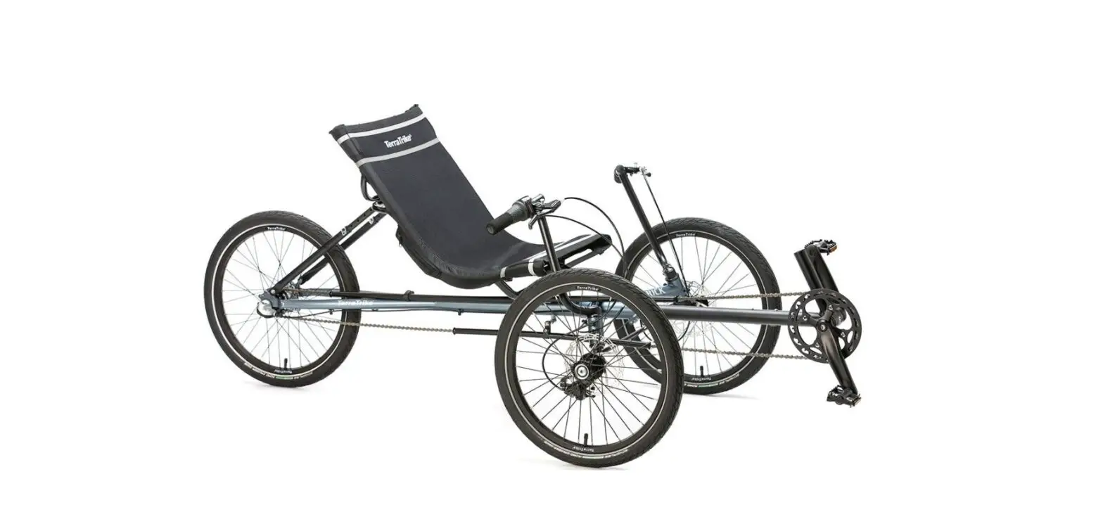
Terra Trike Maverick Nicollet Bike and Ski User Manual
754yju5tf v5 f4 rdf cfe sfefcx
Alignment
Inflate tires before performing alignment. The Maverick alignment measurement is approximately 30¼” (center tread to center tread), though slight variance is possible. Most importantly, make sure the alignment remains neutral with a rider seated in the trike.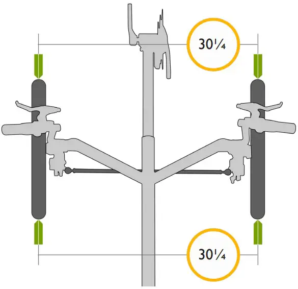
Direct Steering Stack Assembly
Assemble the steering stack as shown. Grease the steerer tube before inserting into head tube. Remove any excess grease from steered tube before installing handlebar. Grease axle before installing wheel. Torque axle bolt to 23-25Nm.
Parts List
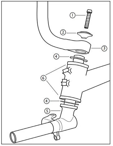
| 1 | M6x18 Bolt | TT000415 |
| 2 | Direct Steer Hub mount Cap | TT000161 |
| 3 | Twist Handlebar – RH | TT000655 |
| Twist Handlebar – LH | TT000646 | |
| Twist Handlebar – Pair | TT000271 | |
| M6x16 Bolt (not pictured) | TT000294 | |
| 4 | M20 Washer | TT000254 |
| 5 | Direct Steer Hub mount – RH | TT000828 |
| Direct Steer Hubmount – RH | TT000829 | |
| Direct Steer Hubmount – Pair | TT000653 | |
| 6 | Bushings (pre-installed) | TT000809 |
Chain Tube Setup
Mount the chain tube assemblies as shown below. Ensure the chain tubes do not rotate in the clamps after tightening the pinch bolts.
Upper: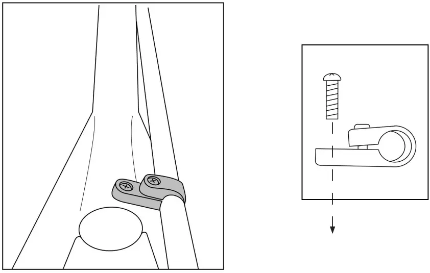
Lower: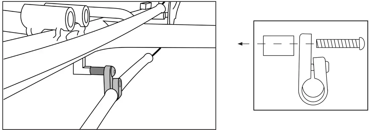
| Upper Assy | Chain Tube, 102cm LDPE | TT000540 | 1 |
| Chain Tube Clamp, Rov/Ram/Mav | TT000152 | 1 | |
| M5x18 Pan Head (phillips) SS | N/A | 2 | |
| Lower Assy | Chain Tube, 56cm LDPE | TT000548 | 1 |
| Chain Tube Clamp, Traveler | TT000422 | 1 | |
| Spacer, 20mm L, 8mm AD x 10mm OD | TT000123 | 1 | |
| M5x18 Pan Head (Phillips) SS | N/A | 1 | |
| M8x40mm BHCS SS | TT000278 | 1 |
Chain Routing
x8 Model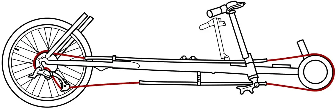
i3 and i8 Models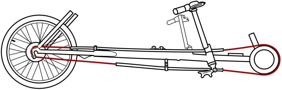
Cable Routing RH x8 Model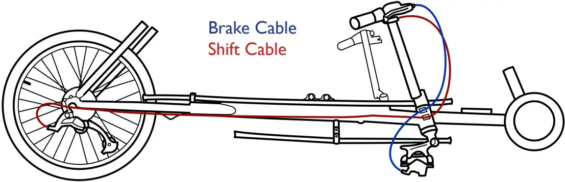
i3 and i8 Models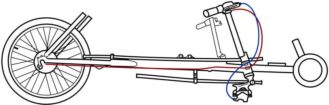
Cable Routing LH (applies to all models)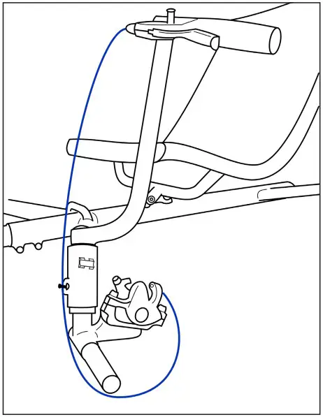
i3 Bell Crank Installation (Refer to Shimano Dealer Manual DM-SG0005-02)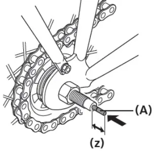
Insert the push rod (A) into the hub axle.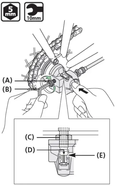
(z) About 14 mm
The push rod should protrude about 14 mm from the end face of the hub axle.
(A) Pushrod
While pushing the bell crank into the hub axle, align the serrations inside thebell crank with the hub nut (C), and continue push until the crank comes into contact with the end face (E) of the hub axle.
While keeping the parts in this position, tighten the bell crank fixing bolt (A) onto the hub axle.
Make sure that the edge (D) of the window is aligned with the end face of the hub axle.
(A) Bell crank fixing bolt
(B) 5 mm hexagon wrench or 10 mm spanner
(C) Hub nut
(D) Edge of the window
(E) End face of the hub axle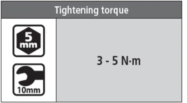
Set the REVOSHIFT lever to 2.
Next, turn the cable adjustment barrel (A) to align the red line (D) on the push rod with the end (C) of the hub axle.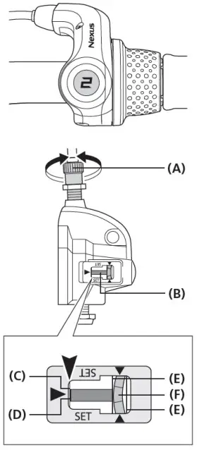
(A) Cable adjustment barrel
(B) Push rod
(C) End of the hub
(D) Red line on the push rod
(E) Yellow lines
(F) Yellow part of the link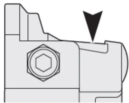
NOTICE
During adjustment, check the two yellow lines through the window from above.
While turning the crank, move the REVOSHIFT lever from 3 to 1 then back to 3. Repeat this two or three times and check to see that the gears are being shifted. Move the REVOSHIFT lever from 1to 2 again and make sure that the red line on the push rod is aligned with the end of the hub axle. If they are not aligned, perform readjustment.
After adjusting the bell crank IV, fix the cable adjustment barrel with the cable adjustment nut (A).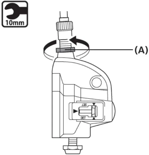
(A) cable adjustment nut
| Tightening torque | |
 | 15-25N-m |
i8 Cassette Joint Installation (Refer to Shimano Dealer Manual DM-CASG001-00)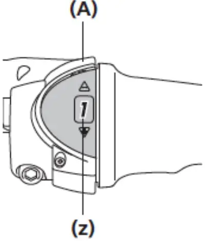
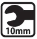
Set the REVOSHIFT lever to 1.
(z) setto1
(A) REVOSHIFT lever
After checking that the end of the outer casing s securely set in the cable adjustment barrel of the REVOSHIFT lever, attach the inner cable mounting bolt unit to the inner cable.
(w) 10mm
(X) Pass the inner cable through the hole.
(y) 101mm
(z) Pull the inner cable when securing.
(A) Inner cable mounting nut (Black)
(B) Inner cable mounting washer (silver)
(C) Inner cable mounting bolt (Silver)
(D) Inner cable mounting bolt unit
| Tightening torque | |
| 3.5-5.5Nm |
NOTE
- This inner cable mounting bolt unit is designed only for CJ-NX10, CJ-NX40, CJ-8520, and CJ-8540. 11-speed mounting bolt units cannot be used.
- The tool is shipped ready to be used for CJ-NX10 and CJ-8520.
- When installing the inner cable mounting bolt unit, use the setting tool TL-CJA0 (Y70898020).
- For CJ-NX10 and CJ-8520, use the front side of TLCJ40.
Front side of TL-CJ40
Bring the cable around to the cassette joint pulley, hold it so that the inner cable fixing nut is facing outwards (towards the fork end), and then slide the flats part of the inner cable fixing washer into the gap in the pulley.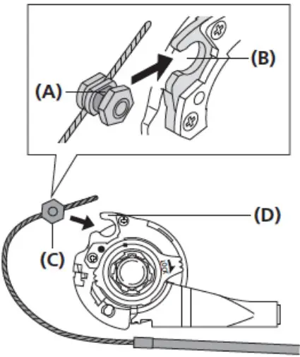
(A) Flats part of inner cable fixing washer
(B) Gap in pulley
(C) Inner cable fixing nut
(D) Pulley
Turn the cable 60° counterclockwise and attach it to the hook.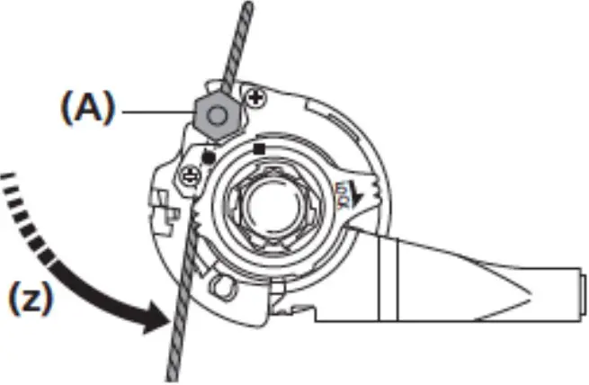
(z) Turn the cable 60°
(A) Hook
Attach the inner cable to the pulley as shown in the illustration, pass the inner cable through the slit in the bracket, and then insert the end of the outer casing securely into the outer casing holder.
800.945.9910
www.TerraTrike.com
4460 40th St. SE | Grand Rapids, Ml 49512 USA
Revised 6/2022