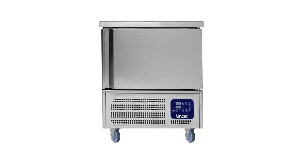
![]() 5P Blast Chiller Freezer
5P Blast Chiller Freezer
User Manual
Lincat BGBF-5P Blast Chiller Freezer
Please make a note of your product details for future use:
Date Purchased:_________________________
Model Number:__________________________
Serial Number:__________________________
Dealer:_________________________________
IMPORTANT INFORMATION
![]() Read these instructions carefully before using this product, paying particular attention to all sections that carry warning symbols, caution symbols and notices. Ensure that these are understood at all times.
Read these instructions carefully before using this product, paying particular attention to all sections that carry warning symbols, caution symbols and notices. Ensure that these are understood at all times.![]() WARNING!
WARNING!
This symbol is used whenever there is a risk of personal injury.![]() CAUTION!
CAUTION!
This symbol is used whenever there is a risk of damaging your Lincat prod![]() NOTE:
NOTE:
This symbol is used to provide additional information, hints a
KEEP THIS MANUAL FOR FUTURE REFERENCE
WARNINGS AND PRECAUTIONS
1.1 TESTING AND INTENDED USE
This equipment is tested in compliance with established regulations and then shipped ready for use.
“If the equipment is used in a manner not specified by the manufacturer, the protection provided by the equipment may be impaired.”
1.2 INTRODUCTION
This manual provides all instructions required for the correct use of the equipment and to keep it in optimal condition. It also contains important user safety information. The following professional roles are explained in order to define individual responsibilities:
Installer: a qualified technician who installs the equipment in accordance with these instructions.
User: the person who, after having read this manual carefully, uses the equipment in accordance with the intended specification of use described in this manual. User’s responsibilities: ensure that the product is kept at suitable temperatures in an ambient environment less than +40°C (104°F); be aware of the regulations governing the conservation of products to refrigerate and to observe any whatsoever hygiene indications that may be applicable. The user is obliged to carefully read the manual and refer to its information at all times. Particular attention must be paid to safety warnings (refer to Section 1.5).
Routine maintenance technician: qualified operator able to perform routine maintenance of the equipment by following the instructions in this manual. Service engineer: qualified technician, authorized by the manufacturer to perform extra or denary main tenancy of the equipment.
Routine maintenance technician: qualified operator able to perform routine maintenance of the equipment by following the instructions in this manual.
Service engineer: qualified technician, authorized by the manufacturer to perform extra or denary main tenancy of the equipment.
The symbol ![]() appears at certain points in the manual to draw the reader’s attention to important safety information.
appears at certain points in the manual to draw the reader’s attention to important safety information.
The manufacturer declines any responsibility in case of improper use of the equipment deviating from the reasonably construed intended use, and for all operations carried out that are not in compliance with the instructions reported in the manual.
This manual must be stored in an accessible and known place for all operators (installer, user, routine maintenance technician, service engineer).
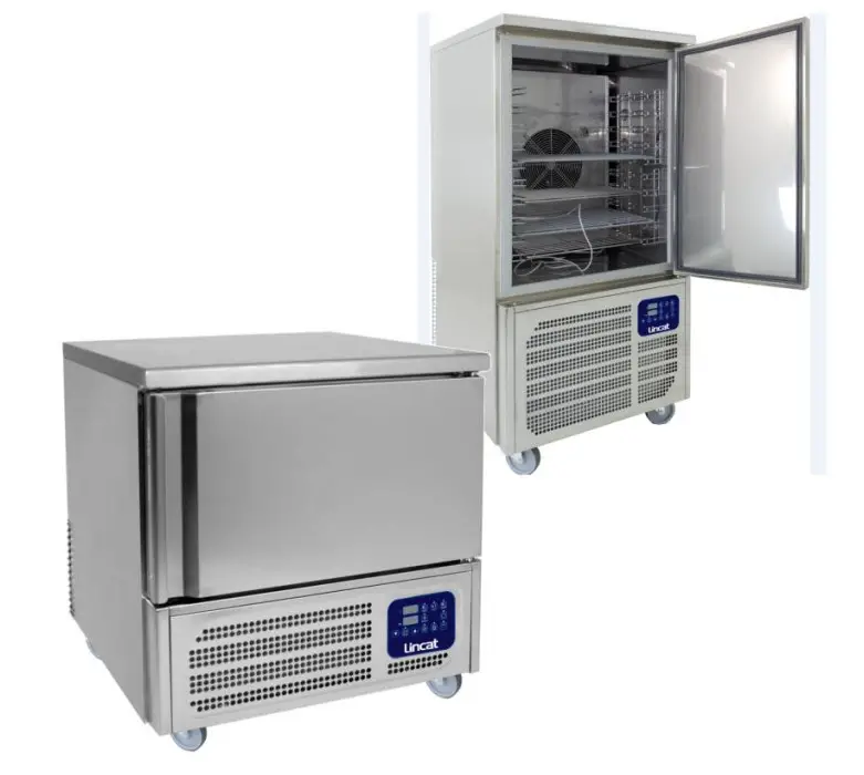
1.3 PRODUCT DESCRIPTION
The equipment comprises a single body with paneling in various materials and insulation with expanded polyurethane foam. The equipment instruments are located on the front panel where the electrical wiring is housed. The interior parts are fitted with suitable supports for shelves. The doors are fitted with an automatic return device and magnetic seal elements. During the design and construction stage all measures have been adopted to implement total safety including radius interior corners, funnel-shaped base panel to convey condensate to exterior, no rough surfaces, fixed guards protecting moving or potentially dangerous parts.
1.4 GENERAL SAFETY REGULATIONS
Read this manual carefully and follow the instructions contained herein.
The user assumes full responsibility in case of operations carried out without observing the instructions in the manual.![]() Do not use this product with flammable gases or flammable solvents.
Do not use this product with flammable gases or flammable solvents.![]() Do not store flammable gases, flammable liquids or flammable solids in these units.
Do not store flammable gases, flammable liquids or flammable solids in these units.
Primary general safety regulations:
- Do not touch the unit with wet hands and/or feet. Do not use the equipment with bare feet;
- Do not insert screwdrivers or other pointed objects between guards or moving parts of the equipment;
- Do not pull the power cord to disconnect the equipment from the electrical mains Make sure that the equipment is not used by unsuitably qualified persons;
- Before performing any cleaning or maintenance on the equipment disconnect it from the electrical mains by switching off the main switch and extracting the plug;
- Never use any metallic scouring pads, brushes, abrasive cleaners or strong alkaline solution on any surface.
- The relocation of the unit must be performed by qualified personnel. Do not shift the refrigerator from side to side as this may create leakage point across the cooling unit piping.
- In case of faults or malfunctions, switch off the equipment and do not attempt to repair it by yourself as doing so may void the warranty. All service and repair operations must be performed exclusively by a manufacture’s authorized engineer. (Authorized service technician, trained service personnel, authorized service personnel)
- This application, like any other appliance, must have access to fresh air/oxygen;
- Keep clear of obstruction all ventilation openings in the appliance enclosure or in the structure for building-in.
- Do not use mechanical devices or other means to accelerate the defrosting process, other than those recommended by the manufacturer.
- WARNING: Do not damage the refrigerant circuit.
![]() Do not use FLAME to check for gas leak.
Do not use FLAME to check for gas leak.![]() Do not under any circumstances try to modify or repair valves, regulator, connectors, controls or any other appliance. Doing so creates the risk of a gas leak.
Do not under any circumstances try to modify or repair valves, regulator, connectors, controls or any other appliance. Doing so creates the risk of a gas leak.
1.5 CUSTOMER’S RESPONSIBILITIES
The customer is required to:
- Execute the electrical connection of the equipment Prepare the place of installation;
- Provide consumable materials for cleaning Perform routine maintenance;
- In the case of power failures or malfunctions do not open the doors, in order to maintain the internal temperature for as long as possible. If the problem persists for more than a few hours, move the contents to a more suitable place.
1.6 CUSTOMER SERVICE REQUESTS
- For all technical problems and any requests for technical service, refer exclusively to the manufacturer’s authorized personnel;
1.7 ORDERING OF SPARE PARTS
- Orders of spare parts should be made by consulting the part reference code and the serial number of your unit. Consult your dealer.
1.8 PRODUCT CONFIGURATION
- Blast chillers and shock freezers are machines used to rapidly cool food, both to prevent the spread of food bacteria and to maintain the qualities, flavour, aromas and texture of chilled food.These machines are used in three distinct ways:
o Temperature reduction of food down to +3°C
o Freezing of food down to -18°C.
o Thawing of food up to max +10°C.
![]() PRODUCTS MUST BE STORED IN ORDER TO ENSURE EFFICIENT AIR CIRCULATION INSIDE THE UNIT AND SHALL NOT COME OUT OF THE SHELF PERIMETER.
PRODUCTS MUST BE STORED IN ORDER TO ENSURE EFFICIENT AIR CIRCULATION INSIDE THE UNIT AND SHALL NOT COME OUT OF THE SHELF PERIMETER.
1.9 RULES OF USAGE
- Do not stack foods that need to be blast chilled and/or frozen.
- Do not exceed the declared number of kilograms and distribute the product evenly in the trays.
- Blast chilling and shock freezing times always refer to products with a maximum thickness of 40 mm.
- Cool the chamber before performing a blast chilling cycle.
- Blast chill only one type of food at a time; different foods have different densities and therefore cycle execution times may vary.
- The core probe must be correctly positioned at the centre of the largest piece of the product, and the tip must never exit the product and/or touch the tray.
- To prevent the core probe from breaking, do not insert it into foods characterised by a temperature higher than 100°C.
- The core probe must always be cleaned after use to avoid malfunctioning.
- Do not cover foods with a lid or other object; the more isolated the product is, the more time will be needed for blast chilling
- If foods are inserted with a temperature greater than 70°C, the machine may be overloaded, increasing blast chilling times and power consumption.
- Do not obstruct the ventilation air inlets.
- The water drip tray in the blast cell must be positioned under the equipment in the dedicated tracks.
- Make sure the drain pipe is positioned inside the drip tray and free it from any obstructions.
- The drip tray must be regularly emptied; to do so, simply extract the tray from the tracks, empty it and re-insert it back into the tracks.
- Do not store explosive substances, such as pressurised containers with flammable propellants, in this device.
1.10 MATERIALS AND REFRIGERANTS
- Materials in contact or potentially in contact with products are in compliance with the relevant directives. The equipment’s designed and built so that contact parts can be cleaned before each use. The refrigerants utilized comply with established regulations.
1.11 WARNING LABELS
Electrical Shock | LABEL A |
 | Use of this equipment involves power supplies which convert line voltage to low voltage power. Do not modify or use power supplies other than OEM equipment. Connection of the power supply may require a properly grounded receptacle. Potential for electrical shock or equipment damage exists if precautions are not followed. |
Hot Surface | LABEL B |
 | Avoid contact with the hot surfaces potential for skin’s burns. |
Cold Surface | LABEL C |
 | Avoid contact with cold freezer surfaces potential for cold burns or skin sticking to cold surfaces. |
Safety Alert | LABEL D |
| Important operating instructions. To reduce the risk of injury or poor performance of the unit read the user manual before putting the equipment into operation. |
Warning | |
 | Indicates an immediately hazardous situation, which if not avoided, will result in death or serious injury. |
Caution | |
| Indicates an immediately hazardous situation, which if not avoided, may result in minor to moderate injury |
Battery | LABEL E |
| Indicates the location of the back-up battery | |
| Risk of fire | LABEL F |
| Risk of fire or explosion. Flammable refrigerant used. Follow handling instruction carefully. To be repaired only by trained service Personnel. Do not puncture Refrigerant Tubing. | |
| This unit is intended for use in laboratories in commercial, industrial or institutional occupancies as defined in the Safety Standard for Refrigeration Systems. | Refrigerating Equipment intended for laboratory use. |
| CAUTION – Risk Of Fire or Explosion due to Flammable Refrigerant Used. Follow Handling Instructions Carefully in Compliance with U.S. Government Regulations. | Packaging markings (Label attached upon the cartoon box) |
| DANGER – Risk Of Fire or Explosion. Flammable Refrigerant Used. To Be Repaired Only By Trained Service Personnel. Do Not Puncture Refrigerant Tubing. | Service markings. (Label located near the cooling unit compartment) |
| CAUTION – Risk Of Fire or Explosion. Flammable Refrigerant Used. Consult Repair Manual/Owner’s Guide Before Attempting To Install or Service This Product. All Safety Precautions Must be Followed. | Service markings (Label located near the cooling unit compartment |
| CAUTION – Risk Of Fire or Explosion. Dispose Of Properly In Accordance With Federal Or Local Regulations. Flammable Refrigerant Used. | Disposal (Marking attached upon the exterior of the cabinet) |
 | Max high load |
TECHNICAL DATA
Environmental Operating Conditions
-Nominal environmental operating condition: Climatic class 5 ( 40°C, HR%=40%);
– Ambient temperature operating range: 10°C~40°C;
– Humidity: 60% maximum, non-condensing;
-Electrical supply: 110~127V/60Hz; 220~230V/50Hz; 220V/60Hz;
-Altitude: 2000 meters MSL (Mean Sea Level);
– Usage: This product is intended for use indoors only.
Below is the table showing the technical data of the various models of blast chillers and freezers.
- Soft blast chilling cycle: Manual with Air set at 0°C
- Hard blast chilling cycle:
o First step air set at 0°C
o Second step air set at -20°C - Shock freezing cycle: Manual with Air set at -40°C
| Model | Blast chilling power consumption [kW] | Shock freezing power consumption [kW] | Blast chilling yield [Kg] | Shock freezing yield [Kg] | Gas charge R452A [Kg] | Blast chilling cycle time (+90°C ÷ +3°C) | Shock freezing cycle time (+90°C ÷ -18°C) |
| BGBF-5P | 1,1 | 0,6 | 14 | 8 | 1,0 | 90 | 270 |
| BGBF-10 | 2,7 | 1,3 | 30 | 20 | 2,0 | 90 | 270 |
Note: All relevant data referring to these products can be found on the data label visible either on the rear part of the cabinet or inside the cooled compartment . Here is an example of the label: 
How to read the Serial Number: YY POP
Last two numbers of the production
XXXXXX
Progressive serial number of 6 digits
INSTALLATION AND COMMISSIONING
3.1 TRANSPORTATION AND HANDLING![]() The equipment must be transported and handled exclusively in upright position, in observance of the instructions printed on the packing.
The equipment must be transported and handled exclusively in upright position, in observance of the instructions printed on the packing.
This precaution is necessary to avoid contamination of the refrigerant circuit with compressor lube oil with resulting valve and heat exchanger coil failure and problems starting the electric motor or the risk of a gas leak. The manufacturer is not responsible for any problems due to transport executed in conditions other than those specified herewith. The equipment is secured to a wooden pallet base, wrapped in a plastic film and packaged into a three waves carton box..
The equipment must be handled using a fork lift truck or a pallet truck with suitable forks (fork length at least equal to 2/3 length of unit).
3.2 POSITIONING
Incorrect positioning can cause damage to the equipment and generate hazardous conditions for personnel. The installer must therefore observe the following general regulations:
- Make sure you maintain a minimum of 11,8” (30cm). clearance from the walls and 19,7” (50 cm) from the sides where the air inlets and outlets are located.. The room must be well ventilated.
- Keep well away from sources of heat. Avoid direct sunlight
- Remove packing material.
- Remove accessories from inside the unit.
- Cartoon box or Wood base removal: using a hammer, tilt the cabinet to one side and loosen the two thread-forming screws, drag the cabinet from the back side holding the base still until the four castors have gone out from the containing holes, slightly tilt the cabinet backward and take the base away pulling it from the front side.
 Use gloves when handling the 3 Waves cartoon box or the wooden base to protect the hands from splinters.
 - Position the equipment with the help of a level. Remove the protective PVC film from the external surfaces of the unit.
Wait 24 hours after positioning the machine before starting it up, thus allowing the oil to return to the compressor and preventing it from breaking.
3.3 WIRING AND ELECTRICAL HOOK-UP
Receptacle installation and electrical wiring operations must be performed by a qualified electrician. For safety reasons adhere to the following indications:
- Check that the electrical plant is suitably sized for the absorbed power of the unit.
- If the electrical socket and the plug on the equipment power cord are incompatible, call technical service or your local distributor.The power cord must be rated for the product and for the voltage and current marked on the product’s electrical ratings label. The voltage and current rating of the cord should be greater than the voltage and current rating marked on the product.
- Do not use reductions or multi-way adaptersIt is important to connect the equipment correctly to an efficient earth system executed in compliance with the relevant legislation.
- The equipment must be positioned so that plug can be easily reached
If the SUPPLY CORD is damaged, it must be replaced by the manufacturer, its service agent or similarly qualified persons in order to avoid a hazard.
3.4 SET UP OPERATIONS
To avoid errors and accidents, perform a series of checks for possible damage sustained during transport, installation and hook-up operations before starting up the unit.
PRELIMINARY CHECKS
- Check the condition of the power cord (no cut or chaffing). Check that the door hinges and shelf support are stable.
- Check the door seal is not damaged (broken or scratched) and that the door closes and seals properly.
- Make sure all copper tubing, unions are in perfect condition.
FOR OPTIMAL PERFORMANCE
- Do not block the motor compartment air vents. Do not lay objects on the top of the equipment
- Arrange the products on suitable shelves or in containers. Do not place products directly on the base or against the walls, doors or fixed guards of the unit.
- Make sure doors are kept closed.
- Keep the defrost water drain outlet clear.
- Limit the frequency and duration of opening; each time the door is opened the internal temperature will alter.
- Load products at ambient temperature gradually to allow correct refrigeration. Perform routine maintenance regularly.
3.5 RE- INSTALLATION
Observe the following procedure:
- Disconnect the power cord from the electrical outlet.
- Handle the equipment in accordance with the instructions in Section 3.1.
- Follow the instructions in Section 3.2 for positioning and hook-ups in the new location.
3.6 SCRAPPING AND DISPOSAL
These units may contain materials, which at the end of the working life of the apparatus, must be disposed at one of the recycling centres nominated by your Local National Health
Department or as specified by the law in force. Scrapping and disposal of the equipment must be carried out in full observance of established legislation in your country.
In particular, the apparatus may contain the following materials:
- Iron
- Copper
- Aluminium
- Non-biodegradable plastics
- Fibre glass for printed circuits
- Ferrite
- Batteries
- CFC-free refrigeration gas
- Electrical and electronic equipment (WEEE)
![]() The manufacturer shall not be chargeable for any disposal of the apparatus at the end of its working life.
The manufacturer shall not be chargeable for any disposal of the apparatus at the end of its working life.
In line with EU Directive 2002/96/EC for waste electrical and electronic equipment (WEEE), this electrical product must not be disposed of as unsorted municipal waste. Please dispose of this product by returning it to your local municipal collection point for recycling.
PROGRAMMING AND OPERATING INSTRUCTIONS
Please read these instructions carefully prior to installation and use this appliance, and follow all the precautions for installation and electrical connections; keep these instructions available for future consultation.![]() The device must be disposed of in accordance with local regulations pertaining to the collection of electrical and electronic appliances.
The device must be disposed of in accordance with local regulations pertaining to the collection of electrical and electronic appliances. 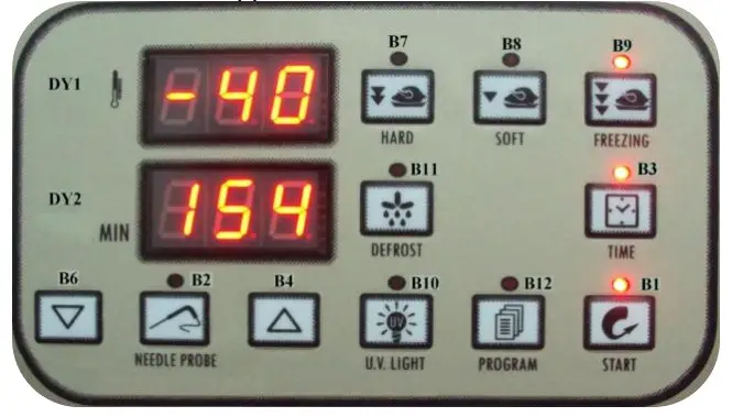
4.1 PRELIMINARY INFORMATION
The device has the following operational states:
- “on” (the device is switched on and an operating cycle is running)
- “stand-by” (the device is switched on and no operating cycle is running, but it is possible to select one)
- “off” (the device is switched off and no operating cycle is running, and it is not possible to select any).
If power is interrupted while in the “on” mode, when power is restored the device will be in the same state and the operational cycle will be restarted from the point reached when the power interruption occurred.
If power is interrupted while in “stand-by” or “off” mode, when power is restored the device will be in the same state.
4.2 SWITCHING THE DEVICE ON/OFF (“off”/”stand-by”)
Ensure no procedures are running
•press B1 for 5 s
The displays will blink for few seconds than the upper display will show the actual air temperature inside the cavity.
In order to switch off the controller, press and hold the B1key for 5 secs, the upper display will show the Affable.
4.3 STARTING/STOPPING AN OPERATIONAL CYCLE (“on”/ “standby”)
In order to stop an ongoing cycle
•press B1and release the controller will switch into the stand-by mode.
The regulators are switched off while in “stand-by” mode.
4.4 THE DISPLAY
In the “on” state, during normal operation, display DY1 shows:
- the temperature measured by the needle probe if a set-temperature chilling or freezing cycle is ongoing
- the temperature of the cabinet if a set-temperature chilling, or timed freezing or a storage cycle is ongoing.
Display DY2 shows:
- the elapsed time for a blast chill or freezing cycle, if these are ongoing
While in “stand-by” mode, display DY1 shows the cabinet temperature and display DY2 shows “- – -“.
While in “off” mode, display DY1 shows “OFF” and display DY2 is off.
4.5 DISPLAYING THE TEMPERATURES DETECTED BY THE PROBES
- Ensure the device is in “off” mode and no procedures are running
- press and holdB2
 + B4
+ B4 for 5 s: display DY1 will show the message “Pr1” and display DY2 will show the cabinet temperature
 - press B4 or B6
 to select one of the labels shown in the table below.
| CODE | MEANING, |
| Pr l | cabinet probe |
| Pr 2 | needle probe |
| Pr3 | evaporator probe |
| Pr4 | condenser probe |
To quit the procedure: press B1![]()
If there is no condenser probe (parameter P3 = 0), label “Pr4” will not be displayed.
4.6 STARTING/STOPPING MANUAL DEFROSTING
To start defrosting in manual mode:
- ensure the device is in “off” mode and no procedures are running
- press B11
 the display DY1 will show “def.”.
If the evaporator temperature is above the value set by parameter P23(8 mins from factory), defrosting will not be activated.
To stop defrosting in manual mode: - press B11
4.7 SWITCHING ON THE UV LIGHT (cabinet sterilisation)
•Ensure that the device is in “stand-by” mode, that no procedures are running and that the micro port input is not active
•press B10![]()
The UV light is turned on for the period of time established by parameter P46(5 mins from factory) or until B10![]() is pressed once more.
is pressed once more.
4.8 HEATING THE NEEDLE PROBE
- Ensure that the device is in “stand-by” mode, that no procedures are running and that the micro port input is not active
- press and holdB2for 5 s: the needle probe will be heated until it reaches the temperature set by parameter P47(45°C from factory) or at most for the period of time set by parameter P48(15mins from factory).
If the temperature detected by the needle probe is above the value set by parameter P47, heating will not be started.
The micro-port input alarm will not be reported during needle probe heating process.
4.9 BUZZER MUTE
•Ensure no procedures are running
•press B4![]() After the period of time established by parameter P56(15 mins from factory) has elapsed, the buzzer is automatically muted.
After the period of time established by parameter P56(15 mins from factory) has elapsed, the buzzer is automatically muted.
4.10 OPERATIONAL CYCLES
The device has the following operational cycles:
- hard set-temperature chilling and storage
- normal set-temperature chilling and storage
- set-temperature freezing and storage
- hard timed chilling and storage
- timed normal chilling and storage
- timed freezing and storage.
Set-temperature cycles are preceded by a test to check correct needle probe insertion (see parameters P14(0°C from factory) and P15(60secs from factory); if the result of the
test is negative, cycles will be started in timed mode.
4.10.1 Hard set-temperature chilling and storage cycle
To select the cycle:
- ensure the device is in “off” mode and no procedures are running
- press B7
 : display DY1 will show the operational set point and LED B7 will switch on.
To adjust the first step operational setpoint: - press B4or B6
To alter the second step operational setpoint: - press B7
 for 5 s: LED B7 will flash
 - press B4or B6
These settings remain active until another cycle is selected. Also, it is possible to set the first step operational setpoint by means of parameter P6(-20°C from factory) and the second step operational setpoint by means of parameter P4(0°C from factory); the hard chill process progresses from the first step to the second when the temperature detected by the needle probe reaches the value set by parameter P12(20°C from factory).
To start the cycle:
- press B1

When the temperature detected by the needle probe reaches the value set by parameter P10(3°C from factory), the buzzer will be activated for the length of time set by parameter P55(3 mins from factory) and the device switches to storage mode. To interrupt the cycle:
- press B1
4.10.2 Normal set-temperature chilling and storage cycle
To select the cycle:
- ensure the device is in “off” mode and no procedures are running
- press B8: display DY1 will show the operational setpoint and LED B8 will switch on.
To adjust the operational setpoint:
- press B4 or B6
These settings remain active until another cycle is selected. It is also possible to set the operational setpoint by means of parameter P4.
To start the cycle:
- press B1
When the temperature detected by the needle probe reaches the value set by parameter P10, the buzzer is activated for the length of time set by parameter P55 and the device
switches to storage mode.
To interrupt the cycle:
- press B1
4.10.3 Set-temperature freezing and storage cycle
To select the cycle:
- ensure the device is in “off” mode and no procedures are running
- press B9
 : display DY1 will show the operational setpoint and LED B9 will switch on.
To adjust the operational set point:
- pressB4 or B6
These settings remain active until another cycle is selected. It is also possible to set the operational set point by means of parameter P5(-40°C from factory).
To start the cycle:
- press B1
When the temperature detected by the needle probe reaches the value set by parameter P11(-18°C from factory), the buzzer is activated for the length of time set by parameter P55 and the device switches to storage mode.
To interrupt the cycle:
- press B1
4.10.4 Hard timed blast chilling and storage cycle
To select the cycle:
- ensure the device is in “off” mode and no procedures are running.
- press B7: display DY1 will show the operational set point and LED L7 will switch on.
To adjust the first step operational set point:
- press B4 or B6
To alter the second step operational set point:
- press B7 per 5 s: LED L7 will flash
- press B4 or B6
It is also possible to set the first step operational set point by means of parameter P6 and the second step operational set point by means of parameter P4.
- press B3 : display DY2 will show the duration of the chilling step and LED L3 will be switched on.
To adjust the duration of the chilling step:
- press B4 or B6
It is also possible to set the chill duration time by means of parameter P16(90mins from factory).
These settings remain active until another cycle is selected. The hard chill process switches from the first step to the second step once the period of time established by parameter P18(45mins from factory) has elapsed.
To start the cycle:
- press B1
When the chill duration time has elapsed, the buzzer is activated for the length of time set by parameter P55 and the device switches to storage mode.
To interrupt the cycle:
- press B1
4.10.5 Normal timed chilling and storage cycle
To select the cycle: ensure the device is in “off” mode and no procedures are running
- press B8: display DY1 will show the operational setpoint and LED L8 will switch on.
To adjust the operational setpoint:
- press B4 or B6
It is also possible to set the operational setpoint by means of parameter P4.
- press B3
 : display DY2 will show the duration of the chilling step and LED L3 will be switched on.
To alter the duration of the chilling step:
- press B4 or B6
It is also possible to set the chill duration time by means of parameter P16.
These settings remain active until another cycle is selected.
To start the cycle:
- press B1
4.10.6 Timed freezing and storage cycle
To select the cycle:
- ensure the device is in “off” mode and no procedures are running
- press B9: display DY1 will show the operational set point and LED L9 wills witch on.
To adjust the operational set point:
- press B4 or B6
It is also possible to set the operational set point by means of parameter P5.
- press B3:
display DY2 will show the duration of the freezing step LED L3 will be switched on.
To adjust the duration of the freezing step:
- pressB4 or B6
It is also possible to set the freeze duration time by means of parameter P17(270 mins from factory).
These settings remain active until another cycle is selected.
To start the cycle:
- press B1
When the freezing step duration time has elapsed, the buzzer is activated for the length of time set by parameter P55 and the device switches to storage mode.
To interrupt the cycle:
- press B1
4.10.7 Storage, selection and starting a program
The device allows storage of operation cycle settings in programs; up to 99 programs can be stored.
To store a program:
- proceed as described in the last paragraphs without starting the cycle
- press B12 for 5 s: display DY1 will show the label of the first unused program
- press B4 or B6to select another label
- press B12 for 5 s: the device will store the program and exit from the procedure (any programs with the same label will be overwritten).
 for 5 s: the device will store the program and exit from the procedure (any programs with the same label will be overwritten).
To select and start a stored program:
- ensure the device is in “stand-by” mode and no procedures are running.
- pressB12: display DY1 will show the label of the first program
- press B4 or B6to select a program
- press B1
To display the label of the current program:
- press B12
4.10.8 Additional functions accessible during operational cycles
To display the cabinet temperature during a set-temperature chilling step or during a setter prelature freezing step:
- press the key related to the current cycle: display DY1 displays the cabinet temperature for 5 s.
To display the temperature detected by the needle probe during a timed chilling step, timed freezing step or during storage:
- press B2 : display DY1 shows the temperature measured by the needle probe for 5s.
To display the time elapsed since starting a chilling or freezing step:
- press B4: display DY2 shows the elapsed time for 5 s.
If the key is pressed during the storage phase, display DY2 will show the effective duration of the chilling or freezing cycle.
4.11 SETTINGS
4.11.1 Setting the date and time
To access the procedure:
- ensure the device is in “off” mode and no procedures are running
To adjust the date and time:
- press B3 for 5 s: display DY1 will show “YY” and display DY2 will show the last two digits corresponding to the year
- press B4 or B6to change the year
- press B3 : display DY1 will show “NN” and display DY2 will show the digits corresponding to the month (the month is displayed in 12 month format)
- pressB4 or B6 to change the month
- press B3: display DY1 will show “dd” and display DY2 will show the digits corresponding to the day (days are displayed in 31 day format)
- pressB4 or B6 to change the day
- press B3 : display DY1 will show “hh” and display DY2 will show the digits corresponding to the hour (hours are displayed in 24 hour format)
- press B4 or B6 to change the hour
- press B3 : display DY1 will show “nn” and display DY2 will show the digits corresponding to the minutes
- press B4 or B6 to change the minutes
- press B3 : the device will exit the procedure.
4.11.2 Setting the configuration parameters
To access the procedure:
- ensure the device is in “off” mode and no procedures are running
- pressB4 or B6 for 5 s: display DY1 will show “PA” and display
DY2 will show the corresponding value.
To select a parameter:
- press B4 or B6
To modify a parameter:
- press B3 : LED L3 will be switched on
- press B4 or B6within 60 s
- press B3
To exit the procedure:
- press B4 or B6for 5s.
4.12 HACCP
The device is capable of storing up to 10 HACCP alarms, after which the most recent alarm will overwrite the oldest.
The device can furnish the following information:
- the critical value
- the date and time at which the alarm occurred
- the alarm duration (from 1 minute to 999 minutes, ” – – -” if the alarm is ongoing).
| CODE | ALARM TYPE (AND CRITICAL VALUE) |
| ErO | Cabinet probe error (the temperature of the cabinet when the alarm condition occurred) |
| Erl | Evaporator probe alarm (the maximum cabinet temperature during the alarm condition) |
| Er3 | Needle probe alarm (the maximum cabinet temperature during the alarm condition) |
| Er4 | Condenser probe alarm (the maximum cabinet temperature during the alarm condition) |
| AL | Minimum cabinet temperature alarm (the minimum cabinet temperature during the alarm condition) |
| AH | Maximum cabinet temperature alarm (the maximum cabinet temperature during the alarm condition) |
| Ht | Condenser temperature alarm (the maximum cabinet temperature during the alarm condition) |
| d – r | Micro port input alarm (the maximum cabinet temperature during the alarm condition) |
| HP | High pressure input alarm (the maximum cabinet temperature during the alarm condition) |
| LP | Low pressure input alarm (the maximum cabinet temperature during the alarm condition) |
| HA | Compressor thermal protection input alarm (the maximum cabinet temperature during the alarm condition) |
| PF | Power failure alarm (the cabinet temperature on restoration of power) |
4.13 VIEWING HACCP ALARM INFORMATION
Viewing HACCP alarm information:
- ensure the device is in “off” mode and no procedures are running
- press B12 for 5 s: display DY1 will show “Prt”.
To select an alarm:
- press B4 or B6 display DY1 will show the number of the alarm (for example “n03”) and display DY2 will show the relevant code (for example “AH”, or one of the codes reported in the table in section 5.1; the lower the number, the older the alarm itself).
To display the information relating to the alarm:
- press B3 repeatedly: the display will show the following information in sequence (for example):
| INFO | MEANING |
| St y07 | on display DY1 on display DY2 The alarm occurred in 2007 (continued …) |
| M03 d26 | on display DY1 on display DY2 The alarm occurred on 26 March 2007 |
| h16 d30 | on display DY1 on display DY2 The alarm occurred at 4:30pm |
| a | on display DY1 on display DY2 The critical value is 8 °C/8 °F |
| dur 75 | on display DY1 on display DY2 The alarm has lasted for 75 minutes |
| DY1 AH | on display DY1 on display DY2 The selected alarm |
LED L13 provides information relating to the status of the HACCP alarm memory; plearefer to section 7.1.
To exit the information series:
- pressB4 or B6 display DY1 will show the number of another alarm and display DY2 will show the corresponding code.
To exit the procedure:
- press B12 for 5 s.
MAINTENANCE AND CLEANING
Maintenance and repair must be carried out by qualified personnel authorized by the manufacturer.![]() The manufacturer declines any responsibility for jobs carried out by unauthorized personnel or the use of non-original spare parts.
The manufacturer declines any responsibility for jobs carried out by unauthorized personnel or the use of non-original spare parts.
5.1 ROUTINE MAINTENANCE![]() Prohibited to remove the guards and safety devices: It’s strictly forbidden to remove guards or safety devices when performing routine maintenance operation. The manufacturer disclaims all liability that may arise this regulation is not observed.
Prohibited to remove the guards and safety devices: It’s strictly forbidden to remove guards or safety devices when performing routine maintenance operation. The manufacturer disclaims all liability that may arise this regulation is not observed.
In case of FIRE:
– Disconnect the unit from the electrical power socket.
– Do not use water to extinguish the fire.
– Use powder or foam extinguishers.
Cleaning the interior and exterior of the appliance
The appliance is designed for the products storage so it is important to keep it clean. The equipment is thoroughly cleaned at the factory before being shipped. We recommend, however, to clean the interior cabinet before the first start up of the appliance. Before attempt any cleaning operation make sure the power cord is disconnected.
– Cleaning product: use soft clean cloth wet with water and neutral detergent only.Do not
use solvent or bleach.
-Rinsing: use a soft cloth or sponge soaked with fresh clean water. Do not use water jet.
-Wipe with a soft, clean towel to prevent water spotting.
Stainless door panels, handles and frames can discolor when exposed to chlorine gas, pool chemicals, saltwater or cleaners with bleach.
Keep your stainless unit looking new by cleaning with a good quality all-in-one stainless steel cleaner and polish monthly. Some installation may require cleaning weekly.
Do not clean with steel wool pads.
Do not use cleaners not specifically intended for stainless steel on stainless steel surfaces.
Condenser cleaning
The condenser is a heat exchanger. If it is dirty or clogged the air cannot circulate freely through the same, it cannot discharge heat properly so reducing proportionally the performance and the efficiency of the refrigeration system.
FOR THOSE REASONS IT IS IMPORTANT TO KEEP CLEAN THE CONDENSER COIL, TYPICALLY MONTHLY.![]() Always switch off the unit and disconnect power cord before cleaning, it is dangerous to do it with power ON: fan may start suddenly at any time.
Always switch off the unit and disconnect power cord before cleaning, it is dangerous to do it with power ON: fan may start suddenly at any time.
Use a convenient ladder to reach the condenser. Use an air jet or vacuum with a soft drybrush if necessary and remove any dust or fluff from the heat exchanger fins.
After cleaning, start the equipment.![]() During the cleaning operation wear gloves and safety glasses to protect yourself from any injury
During the cleaning operation wear gloves and safety glasses to protect yourself from any injury
MESSAGES AND INDICATIONS
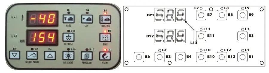
6.1 MESSAGES
| L1 “On”/”Stand-by” LED -if operantly ON, a chilling or freezing go predation is ongoing -if flashing, a storage operation is ongoing | L2 Needle probe LED -if permanently ON, the temperature measured by the needle probe is being displayed -if flashing, then the result of the test toverify correct needle probe insertion was negative; the cycle will be started in timed mode and the buzzer will emit 5 beeps every 10s |
| L3 Timed operation cycle LED -if permanently on, a timed operation cycle will have been selected (or is ongoing | L7 hard chill LED -if permanently ON: ·a hard chill operation will have been selected ·the first step of a hard chill operation is ongoing ·modification of the hard chill first step operational setpoint is underway -if flashing: •modification of the hard chill second step operational setpoint is underway •the second step of a hard chill operation is in progress |
| L8 Normal chilling LED -if permanently on, a normal chill operation has been selected (or is ongoing) | L9 Freezing LED -if permanently on, a freezing operation has been selected (or is ongoing) |
| L10 UV light (cabinet sterilisation) LED -if permanently on, the UV light is on (acabinet sterilisation operation is ongoing) | L11 Defrosting LED -if permanently on, defrosting is ongoing |
| L12 Program LED -if permanently on, program storing, selection or execution is ongoing | L13 HACCP LED if permanently on, program storing, selection or execution is ongoing |
6.2 INDICATIONS
dEF -if permanently on, defrosting is ongoing
-if flashing: drip-draining is ongoing
ALARMS AND INTERNAL DIAGNOSTICS
| AL Minimum cabinet temperature alarm -Remedies: •check the cabinet temperature •see parameters P64 and P66 -Consequences: •the alarm output will be activated | AH Maximum cabinet temperature alarm -Remedies: •check the cabinet temperature •see parameters P65 and P67 -Consequences: •the alarm output will be activated |
| Ht Condenser temperature alarm -Remedies: •check the condenser temperature •see parameter P62 -Consequences: •the operational cycle will be interrupted •it will not be possible to start any operational cycles •the condenser fan will be switched on •the alarm output will be activated | d-r Micro-port input alarm Remedies: •check the causes of the input activation •see parameter P38 -Consequences if the alarm occurs while in “on” mode: •the compressor will be shut down •if parameter P37 is set to 1, the evaporator fan will be switched off •if parameter P59 is set to 0, the cabinet light will be switched on •the condenser fan will be switched off •if the UV light is on (i.e. if cabinet sterilisation is ongoing), the UV light will be switched off |
| PH High pressure input alarm -Remedies: •check the causes of the input activation •see parameter P40 -Consequences: •the operational cycle will be interrupted •the loads will be switched off •it will not be possible to start any operational cycles •the alarm output will be activated | LP Low pressure input alarm -Remedies: •check the causes of the input activation •see parameter P42 -Consequences: •the operational cycle will be interrupted •the loads will be switched off •it will not be possible to start any operational |
| HA Compressor thermal protection input alarm -Remedies: •check the causes of the input activation •see parameter P44 Consequences: •the operational cycle will be interrupted•the loads will be switched off •it will not be possible to start any operational cycles •the alarm output will be activated | HA Compressor thermal protection input alarm -Remedies: •check the causes of the input activation •see parameter P44 Consequences: •the operational cycle will be interrupted•the loads will be switched off •it will not be possible to start any operational cycles •the alarm output will be activated |
When the cause that triggered the alarm has been resolved, the device restores normal operation
7.2 INTERNAL DIAGNOSTICS
| Er0 Cabinet probe error -Remedies: •see parameter P60 •check probe integrity •check probe-device connection •check the cabinet temperature -Consequences: •the operational cycle will be interrupted •the loads will be switched off •it will not be possible to start any operational cycles •the alarm output will be activated | Er1 Evaporator probe error -Remedies: •the same as for the previous case, but in relation to the evaporator probe -Consequences: •defrosting will last for the length of time set by parameter P24 •the evaporator fan will be switched off during storage •the alarm output will be activated |
| Er3 Needle probe error -Remedies: •the same as for the previous case, but in relation to the needle probe -Consequences: •if a set-temperature chilling or freezing operation is ongoing, the operational cycle will be interrupted •it will not be possible to start any setter prelature operational cycles •the alarm output will be activated | Er4 Condenser probe error -Remedies: •the same as for the previous case, but in relation to the condenser probe -Consequences: •the condenser fan will operate in parallel with the compressor, except when set by parameter P54 •the alarm output will be activated |
| Err User interface-module communication error -Remedies: •check the user interface-module connection -Consequences: •if an operational cycle is ongoing, the device will continue to function normally •it will not be possible to start any operational cycles | |
When the cause that triggered the alarm has been resolved, the device restores normal operation.
CONFIGURATION PARAMETERS
| Parameter | Description | Factory value |
| P0 | Unit of Temperature measurements 0=°F 1=°C | 1 |
| P1 | Cabinet probe offset | 2 |
| P2 | Evaporator probe offset | 0 |
| P3 | Needle probe offset | 0 |
| MAIN CONTROLLER PARAMETERS | ||
| P4 | Operational setpoint during Hard chill cycle second step; also operation setpoint during normal chilling (with reference to the cabinet probe) | 0 |
| P5 | Operational setpoint during freezing cycle (with reference to the cabinet probe) | -40 |
| P6 | Operational setpoint during Hard chill cycle first step (with reference to the cabinet probe) | -20 |
| P7 | Operational setpoint of storage mode after chilling cycle (with reference to the cabinet probe) | 3 |
| P8 | Operational setpion of storage model after freezing cycle (with reference to the cabinet probe) | -20 |
| P9 | P4, P5, P6, P7 and P8 differential | 1 |
| P10 | Set Chilling cycle end temperature (with reference to the needle probe) | 3 |
| P11 | Set Freezing cycle end temperature (with reference to the needle probe) | -18 |
| P12 | Temperature at which the Hard cycle switches from the first step to the second step (with reference to the needle probe) | 20 |
| P13 | Temperature above which it is not possible to start a set- temperature operational cycle (with reference to the needle probe) | 99 |
| P14 | Needle probe and the cabinet temperature for verification of correct needle probe insertion (3) 0 = the test will not be performed | 0 |
| P15 | Duration of the second test to check correct needle probe insertion; see also P14 (4) | 60 |
| P16 | Maximum set temperature chill duration; also timed chill duration | 90 |
| P17 | Maximum set temperature freeze duration; also timed freeze duration | 240 |
| P18 | Duration of the Hard chilling cycle first step in time-set mode | 45 |
COMPRESSOR PROTECTION PARAMETERS | ||
| P19 | Compressor activation delay from device power on (from restoration of power) | 0 |
| P20 | Minimum elapsed time period between two consecutive compressor start-up operations | 1 |
| P21 | Minimum compressor shut-down time | 1 |
| DEFROST PARAMETERS | ||
| P22 | Defrost type (5) 0 = electric (defrost on relay) 1 = hot gas (defrost compressor and relay on) 2 = air (evaporator fan on) | 1 |
| P23 | defrost end temperature (with reference to the evaporator probe) | 8 |
| P24 | Maximum defrost duration | 10 |
| P25 | Defrost interval during storage; see also P26 0 = intervalled defrosting will never be activated (only the first will be activated) | 6 |
| P26 | First defrost delay from start of storage mode; see also P25 | 1 |
| P27 | Defrosting at start of chilling and freezing 1 = YES | 0 |
| P28 | Drip-drain step duration | 2 |
| P29 | Resetting of compressor protections at start of defrosting (only if P22 = 1) 1 = YES | 0 |
| P30 | Elapsed time between the defrost request and switching on the compressor (only if P22 = 1 and providing that the compressor is off when the defrost is requested); see alsoP31 (7) (8) | 30 |
| P31 | Elapsed time between the defrost request and activation of the solenoid valve (only if P22 = 1 and on condition that the compressor is off when defrosting is requested); see also P30 (7) (8) | 0 |
| EVAPORATOR FAN PARAMETERS | ||
| P32 | Temperature above which the evaporator fan is switched off during storage mode (with reference to the evaporator probe) | 3 |
| P33 | P32 differential | 1 |
| P34 | Evaporator fan activity during defrosting (only if P22 = 0 or 1) 0 = on 1 = off | 0 |
| P35 | Evaporator fan activity during defrosting (only if P22 = 0 or 1) | 3 |
| P36 | Temperature above which the evaporator fan is switched off (with reference to the cabinet probe) | 90 |
| P37 | Effect caused by activation of micropart input on evaporator fan 0 = no effect 1 = the evaporator fan will be switched off | 1 |
| DIGITAL INPUTS PARAMETERS | ||
| P38 | Micropart input contact type 0 = NA (input active with contact closed) 1 = NC (input active with contact open) | 1 |
| P39 | Micro port input alarm delay (9) | 0 |
| P40 | High pressure input alarm delay | 1 |
| 0 = NA (input active with contact closed) 1 = NC (input active with contact open) | ||
| P41 | High pressure input alarm delay | 120 |
| P42 | Low pressure input contact type 0 = NA (input active with contact closed) 1 = NC (input active with contact open) | 0 |
| P43 | Low pressure input alarm delay | 0 |
| P44 | Compressor thermal protection input contact type 0 = NA (input active with contact closed) 1 = NC (input active with contact open) compressor thermal protection input alarm | 0 |
| P45 | Compressor thermal protection input alarm delay | 0 |
| STERILIZATION CYCLE PARAMETERS | ||
| P46 | UV light on duration (duration of cabinet sterilisation cycle) | 5 |
| NEEDLE PROBE HEATING CYCLE | ||
| P47 | Needle probe heating end temperature (with reference to the needle probe) | 45 |
| P48 | Maximum duration of needle probe heating | 15 |
| DOOR FRAME HEATER PARAMETERS | ||
| P49 | The temperature, below which the door frame heater elements are switched on (with reference to the cabinet probe) | 5 |
| P50 | P49 differential | 2 |
| CONDENSER FAN PARAMETERS | ||
| P51 | Condenser fan activity in the absence of the condenser probe (P61 = 0) 0 = in parallel with compressor 1 = on | 1 |
| P52 | The temperature below which the condenser fan is switched off in the presence of the condenser probe (P61 = 1) and on condition that the compressor is on (with reference to the condenser probe); see also P54 | 20 |
| P53 | P52 differential | 5 |
| P54 | condenser fan switch off delay on switching off the compressor in the presence of the condenser probe (P61 = 1); see also P52 | 30 |
| OTHER FUNCTIONS PARAMETERS | ||
| P55 | Chill and freeze cycle completion buzzer duration | 3 |
| P56 | maximum buzzer duration during an alarm state | 15 |
| P57 | Elapsed time between switching on the compressor and pump down valve activation (pump down in power up); also elapsed time between deactivation of the pump down valve and switching off the compressor (pump down in power down) | 3 |
| P58 | Defrost parameter units of measurement 0 = P25 h, P24, P26, P28 and P35 min 1 = P25 min, P24, P26, P28 and P35 s | 0 |
| P59 | Reserved (no use) | 0 |
| P60 | Probe type 0 = NTC 1 = PTC | 0 |
| P61 | Condenser probe enabling 1 = YES | 0 |
| CONDENSER HIGH TEMPERATURE PARAMETERS | ||
| P62 | The temperature above which the condenser temperature alarm is activated (with reference to the condenser probe) | 70 |
| P63 | P62 differential | 10 |
| TEMPERATURE ALARMS PARAMETERS | ||
| P64 | Temperature below which the minimum temperature alarm is activated during post-chill storage, with relation to P7, i.e. “P7 + P64” (with reference to the cabinet probe) 0 = no alarm | 0 |
| P65 | Temperature above which the maximum temperature alarm is activated during post-chill storage, with relation to P7, i.e. “P7 + P65” (with reference to the cabinet probe) 0 = no alarm | 0 |
| P66 | Temperature below which the minimum temperature alarm is activated during post-freezing storage, with relation to P8, i.e. “P8 + P66” (with reference to the cabinet probe) 0 = no alarm | 0 |
| P67 | Temperature above which the maximum temperature alarm is activated during post-freezing storage, with relation to P8, i.e. “P8 + P67” (with reference to the cabinet probe) 0 = no alarm | 0 |
| P68 | P64, P65, P66 and P67 differential | 2 |
| P69 | Storage operation start-up temperature alarm delay | 0 |
| P70 | Temperature alarm delay | 0 |
| DATA PRINTING PARAMETERS | ||
| P71 | Enable printing 1 = YES | 0 |
| P72 | Print interval | 5 |
| P73 | HACCP alarm list deletion 1 = YES (10) | 0 |
| P74 | Reserved | 2 |
| P75 | Reserved | 2 |
| P76 | Reserved | 1 |
![]() CAUTION! The modification of the operational parameters without authorization of the manufacturer causes the lost of guarantee.
CAUTION! The modification of the operational parameters without authorization of the manufacturer causes the lost of guarantee.
NOTE:
- Altering parameter P0 effects all parameters where the unit of measurement is degrees Celsius or degrees Fahrenheit.
- The unit of measurement depends on parameter P0
- The test result is positive if the difference between the temperature measured by the needle probe and the cabinet temperature is greater than the value set by parameter P14 at least 3 times out of 5 (checking is every 10 s); if the test result is negative a second test is initiated (se parameter P15)
- The result of the second test is positive if the difference between the temperature measured by the needle probe and the cabinet temperature increases by at least 1_C/1_F with respect to the previous check at least 6 times out of 8 (checking occurs every P15/8 s); if parameter P15 is set to a value of less than 5 s, the second test will not be executed
- If parameter P22 is set to 2, micro port input activation will not be signalled
- The unit of measurement depends on parameter P58
- Defrosting will be activated on conclusion of the time which is greatest between those set by parameters P30 and P31
- If defrosting is requested when the compressor is on and the time set by parameter P30 is less than the value set by parameter P31, the compressor will remain on and the solenoid valve and defrosting will be activated after the time “P31 – P30” has elapsed since the defrost request; vice versa, if defrosting is requested when the compressor is on and the time set by parameter P30 is greater than that set by parameter P31, when defrosting is requested the compressor will be switched off for the greater of the times between those set by parameters P19, P20 and P21 after which the compressor and defrosting will be activated (the solenoid valve will be activated “P30 – P31” s prior to activation of defrosting)
- Parameter P39 has no effect during UV light switch on (cabinet sterilisation)
- Altering parameter P73 is effective on exiting the configuration parameter setting procedure; as soon as you will quit the configuration parameters setting procedure, parameter P73 will automatically get Value 0.
SPARE PARTS LIST
BGBF-5P
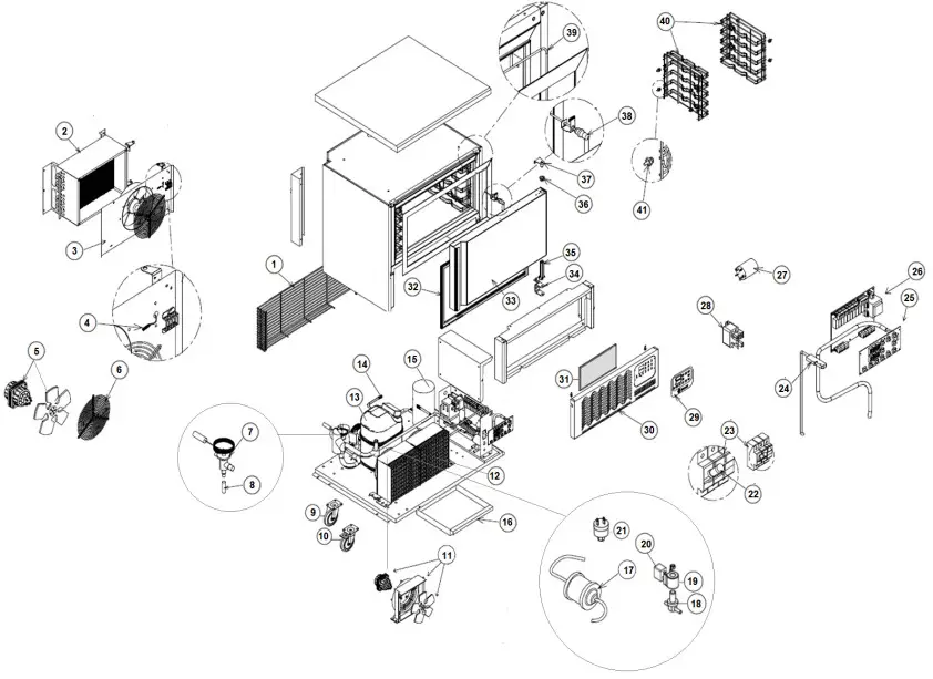
| Item n. | Description |
| 1 | MOTOR COMPARTMENT REAR PLASTIC COATED GRID |
| 2 | EVAPORATOR COIL |
| 3 | SS EVAPORATOR COVER W/FAN HOLDER |
| 4 | NTC TEMPERATURE PROBE |
| 5 | EVAPORATOR FAN MOTOR |
| 6 | EVAPORATOR FAN GRID Φ=250mm |
| 7 | TX EXPANSION VALVE |
| 8 | TX ORIFICE |
| 9 | SWIVEL CASTOR W/OUT BRAKE |
| 10 | SWIVEL CASTOR W/BRAKE |
| 11 | -NOT USED- |
| 12 | CONDENSER ASSY |
| 13 | COMPRESSOR |
| 14 | PRESSURE SCHRADER VALVE |
| 15 | LIQUID RECEIVER |
| 16 | CONDENSATE PAN MOD. GBF-5 |
| 17 | FILTER DRIER |
| 18 | HOT GAS DEFROST SOLENOID VALVE BODY |
| 19 | SOLENOID VALVE COIL |
| 20 | SOLENOID VALVE COIL SUPPLY CABLE |
| 21 | HIGH PRESSURE SWITCH |
| 22 | FUSE 500V 10,3×38 16A |
| 23 | FUSE HOLDER 10,3×38 (UL) |
| 24 | MAGNETIC DOOR SWITCH |
| 25 | DISPLAY KEYBOARD MOD. 2D |
| 26 | CONTROLLER POWER BOARD |
| 27 | NET FILTER |
| 28 | COMPRESSOR POWER RELAY |
| 29 | DISPLAY STICKER DESMON BRANDED |
| 30 | FRONT PANEL MOD. GBF-5G/P |
| 31 | CONDENSER HONEYCOMB AIR FILTER |
| 32 | DOOR GASKET |
| 33 | DOOR FOAMED PANEL MOD. GBF-5P |
| 34 | DOOR BOTTOM BRACKET |
| 35 | DOOR SPRING HINGE KIT |
| 36 | DOOR UPPER HINGE BUSH φ=32 Φi=14,2 |
| 37 | UPPER R/L HINGE MOD. GBF-5G/P |
| 38 | NEEDLE PROBE SINGLE CORE NTC 10kOhm |
| 39 | DOOR FRAME HEATER 19,8W 230W Length=3980mm |
| 40 | SS RACK MOD. 5PANS |
| 41 | SHELVE RACK HOOK |
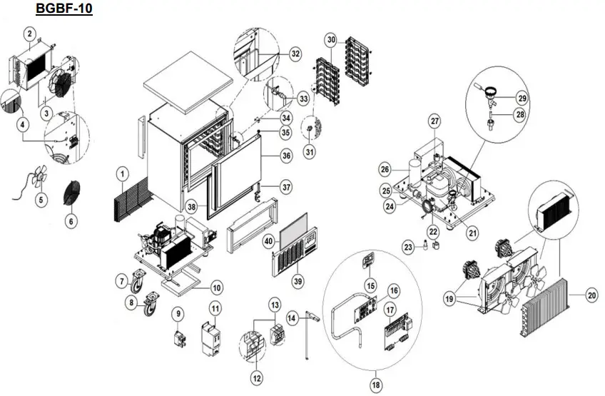
| Item n. | Description |
| 1 | MOTOR COMPARTMENT BACK PRTCN GRID |
| 2 | EVAPORATOR COIL |
| 3 | EVAPORATOR COVER AND FAN HOLDER MOD. GBF-10 |
| 4 | NTC TEMPERATURE PROBE |
| 5 | EVAPORATOR FAN |
| 6 | EVAPORATOR FAN GRID PRTCN 120x120mm Φ=300mm |
| 7 | CASTOR W/OUT BRAKE |
| 8 | SWIVEL CASTOR W/BRAKE |
| 9 | -NOT USED- |
| 10 | CONDENSATE TRAY |
| 11 | CONTACTOR |
| 12 | FUSE 10,3×38 500Vac 20A |
| 13 | FUSE HOLDER 10,3×38(UL) |
| 14 | MAGNETIC DOOR SWITCH |
| 15 | BLAST CHILLER KEYPAD STICKER MOD. DESMON BRANDED |
| 16 | DISPLAY KEYBOARD MOD. 2D |
| 17 | CNTRL POWERBOARD |
| 18 | BLAST CHILLER CONTROLLER KIT |
| 19 | CONDENSER FAN ASSY |
| 20 | CONDENSER COIL |
| 21 | COMPRESSOR |
| 22 | HOT GAS DEFROST SOLENOID VALVE COIL |
| 23 | HOT GAS DEFROST SOLENOID VALVE BODY |
| 24 | FILTER DRIER |
| 25 | HIGH PRESSURE SWITCH |
| 26 | LIQUID RECEIVER |
| 27 | SCHRADER PRESSURE VALVE 1/4″ 6x300mm |
| 28 | TX VALVE ORIFICE |
| 29 | TX EXPANSION VALVE |
| 30 | SHELVE RACK MOD. GBF-10 |
| 31 | INOX SHELF RACK HOOK |
| 32 | FRAME HEATER 44W 220V L4400 |
| 33 | NEEDLE PROBE 10kOhm NTC SINGLE CORE |
| 34 | R/L DOOR UPPER HINGE W/PIVOT |
| 35 | DOOR UPPER HINGE BUSH φ=32 Φi=14,2 |
| 36 | DOOR FOAMED PANEL MOD. GBF-10 |
| 37 | DOOR SPRING HINGE KIT |
| 38 | DOOR GASKET |
| 39 | MOTOR COMPARTMENT FRONT PANEL MOD. GBF-10 |
| 40 | HONEYCOMB CONDENSER FILTER |
SERVICE INFORMATION
For help with the installation, maintenance and use of your Lincat equipment,please contact our service department:
UK: 01522 875520
For non-UK customers, please contact your local Lancet dealer
All service work, other than routine cleaning should be carried out by one of our authorised service agents. We cannot accept responsibility for work carried out by other persons.
To ensure your service enquiry is handled as efficiently as possible, please tell us:
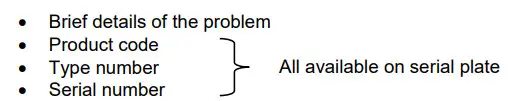
Lincat reserve the right to carry out any work under warranty, given reasonable access to the appliance, during normal working hours, Monday to Friday, 08:30 to 17:00.
GUARANTEE
This unit carries a comprehensive UK mainland 2 year warranty. The guarantee is in addition to, and does not diminish your statutory or legal rights.
The guarantee does not cover:
- Accidental damage, misuse or use not in accordance with the manufacturer’s instructions
- Consumable items (such as filters, glass, bulbs, slot toaster elements and door seals.)
- Damage due to incorrect installation, modification, unauthorised service work or damage due to scale, food debris build-up, etc.
The manufacturer disclaims any liability for incidental, or consequential damages.
Attendance is based on reasonable access to the appliance to allow the authorised technician to carry out the warranty work.
Service calls to equipment under warranty will be carried out in accordance with the conditions of sale.
![]()


