ICP DAS I-7531-FD Two-Channel Isolated CAN-CAN FD Signal Repeater
Packing List
In addition to this guide, the package includes the following items:
- I-7531-FD

- Plastic rail


Resources
How to search for drivers, manuals and spec information on ICP DAS website.
- For Mobile Web

- For Desktop Web


Technical Support
[email protected] www.icpdas.com
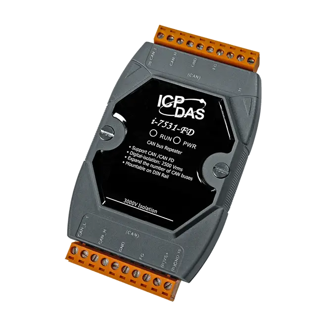
Appearance
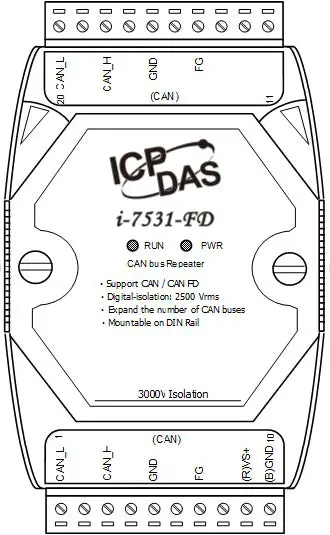
| Number | Description |
| 1 | CAN port 1 |
| 2 | CAN port 2 |
| 3 | LED indicators |
LED indicators
| LED | Color | Status | Description |
| 1 (PWR) | Red | ON | Power on |
| OFF | Power off | ||
| 2 (RUN) | Green | Blink | In communication |
| OFF | No data in communication |
Note 1: Twinkling rate correlates of RUN LED with baud rate of CAN bus. Users may see no twinkling when the twinkling period is too short because of the higher baud rate of CAN bus. Besides, the LED could look like always on when bus loading is heavy.
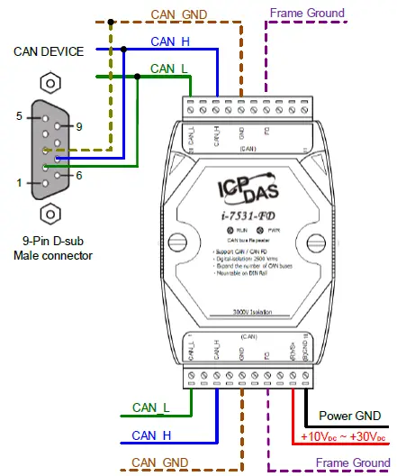
Pin assignments
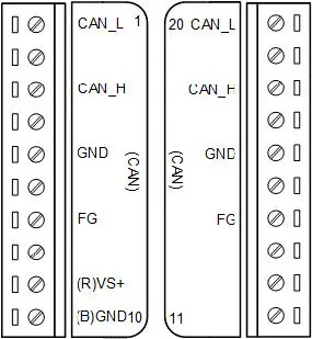
| Pin | Name | Description |
| 1 | CAN_L | CAN_ Low. Signal Line of CAN port 1. |
| 3 | CAN_H | CAN_ High. Signal Line of CAN port 1. |
| 5 | GND | CAN_ Ground (or CAN_GND), voltage level of ground of CAN_L and CAN_H in CAN port 1. |
| 7 | FG | Frame Groud. |
| 9 | (R)VS+ | Power input +10VDC ~ +30VDC. |
| 10 | (B)GND | |
| 14 | FG | Frame Groud. |
| 16 | GND | CAN_ Ground (or CAN_GND), Voltage level of ground of CAN_L and CAN_H in CAN port 2. |
| 18 | CAN_H | CAN_ High. Signal Line of CAN port 2. |
| 20 | CAN_L | CAN_ Low. Signal Line of CAN port 2. |
Terminator Resistor Setting
The JP1 of I-7531-FD is used for adjusting terminal resistor (120Ω) on CAN Port 1, and the JP2 for CAN Port 2. If the user want to adjust the terminal resistor that need to open the cover of I-7531-FD, and will see the locations of JP1 and JP2 are shown as following figure: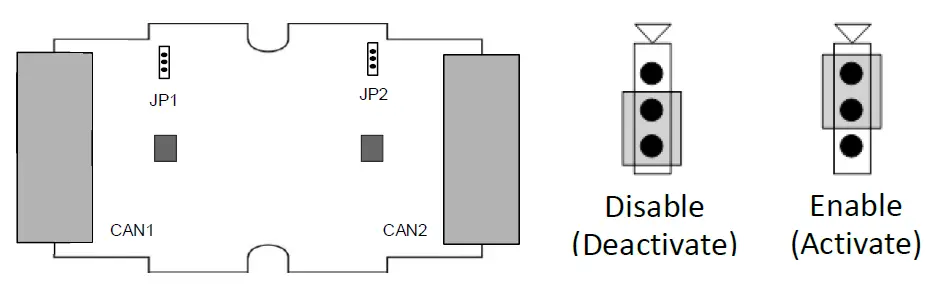
Wire Connections