![]()
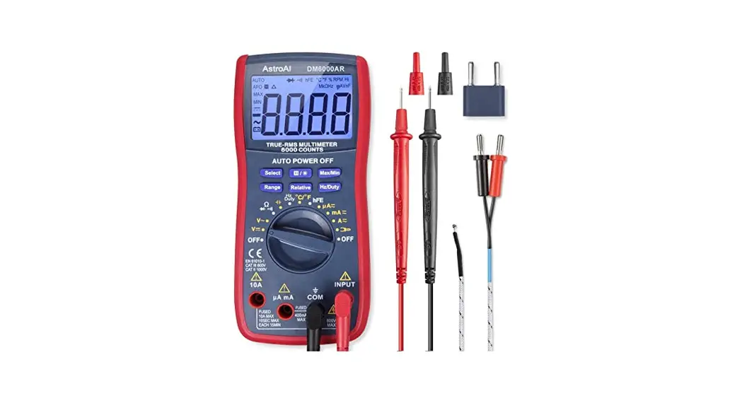
True RMS 6000 Count
Digital Multimeter

V1.0
Thank you for purchasing the True RMS 6000 Count Digital Multimeter from AstroAI. The AstroAI True RMS Digital Multimeter is designed to be safely and accurately used by professionals or DIYer’s that need a little more utility from their standard digital multimeter. This manual provides all safety information, operation instruction, specifications, and maintenance for the meter. The instrument performs AC/DC Voltage, AC/DC Current, Resistance, Audible Continuity, Diode, Frequency, Duty Ratio, Capacitance, NCV Detection, Live Wire Detection, and Temperature Testing. Thank you again for choosing AstroAI, if you have any questions or concerns regarding your product, please contact us at [email protected].
NOTE: Fully read and understand this manual before using this Digital Multimeter.
WARNING
To avoid possible electric shock or personal injury, and to avoid possible damage to the Meter or to the equipment being tested, adhere to the following rules:
- Before using the Meter, inspect the exterior casing. Do not use the Meter if it is damaged or if all or part of the exterior casing is removed. Look for cracks or missing plastic. Pay special attention to the insulation around the connectors.
- Comply with local and national safety regulations. Wear personal protective equipment (such as approved rubber gloves, masks, and flame-retardant clothing, etc.) to prevent injury from electric shocks and arcs when hazardous live conductors are exposed.
- Check whether the Meter is working normally by measuring the known voltage, do not use if the readings are incorrect or the Meter is damaged.
- When servicing the Meter, use only the same model number or identical electrical specifications replacement parts.
- When using the test leads, keep your fingers behind the finger guards.
- Do not apply more than the rated voltage, as marked on the Meter, between the terminals or between any terminal and grounding.
- Do not use or store the Meter in a high-temperature environment, do not expose to high levels of humidity, or near strong magnetic fields. The performance of the Meter
may deteriorate after dampening. - When the Meter is working at an effective voltage over 60V in DC or 30V rms in AC, special care should be taken because there is a danger of electric shock.
- When measuring, connect the neutral wire or ground wire first, and then connect the live wire; when disconnecting, disconnect the live wire first, and then disconnect the neutral wire and the ground wire.
- Replace the battery as soon as the battery indicator appears. With a low battery, the Meter might produce false readings that can lead to electric shock and personal injury.
- Remove the connection between the testing leads and the circuit being tested and turn the Meter power off before opening the Meter case.
- The manual rotary switch should be placed in the correct position before measurement and should NOT be moved during measurement to prevent damage to the Meter.
- Turn the Meter off when not in use and take out the battery when it is not going to be used for an extended period. Regularly check the battery as it may leak when it has not been used for some time. Replace the battery as soon as leaking appears. A leaking battery will damage the Meter.
ELECTRICAL SYMBOLS
 | Warning |  | Dangerous Voltage |
| AC (Alternating Current) | Earth Ground | ||
| DC (Direct Current) | Fuse | ||
| AC and DC | Double Insulation | ||
| Low Battery Symbol | Compliance with EU Standards | ||
| CATⅢ | Category III test equipment is suitable for testing and measurements of circuits connected to the power distribution portion of a low-voltage power supply unit in a building. | ||
| CATIV | Category IV test equipment is suitable for testing and measurements of circuits connected to the power supply of a low-voltage power supply unit in a building. | ||
MULTIMETER DIAGRAM


- NCV Detector
- Flashlight Button
- Indicator Light
- LCD Screen
- Function buttons
- Rotary Function Switch
- 10A Terminal
- INPUT Terminal
- COM Terminal
- μA/mA Terminal
- Test Leads
- K-Type Thermocouple
GETTING TO KNOW YOUR DEVICE
- BUTTONS FUNCTIONS
 | |
| Button | Function |
 |
|
 |
|
 |
|
 |
|
- SETTING FUNCTION
 | |
| Setting | Function |
| NOTE: Use the FUNC Button to further select the function if there are multiple functions in one rotary setting. | |
| V | DC Voltage Test : 0-1000v AC Voltage Test : 0-750v |
| mV | AC/DC Voltage Test: 0-600mv |
| Ω | Resistance Test: 0.10-60M0 |
| Capacitance Test : 0.001nF-100mF | |
 | Audible Continuity Test |
| Diode Test | |
| Hz | Frequency |
| % | Duty Cycle |
| A | AC/DC Current Test : 0~10A |
| mA | AC/DC Current Test : 0~600mA |
| μA | AC/DC Current Test : 0~6000uA |
| ℉ | Fahrenheit Temperature |
| ℃ | Celsius Temperature |
| NCV | NCV Detection |
| Live | Live Wire Detection |
TERMINALS
 | |
| 1 | Plug the red test lead into this terminal for currents between 600mA and 10A. |
| 2 | Plug the red test lead into this terminal for currents less than 600mA. |
| 3 | Plug the red test lead into this terminal for all measurements except the current. |
| 4 | Plug the black test lead into this terminal. |
- OTHER FUNCTIONS
Auto Shut Off:
- After 15 of standby, the Meter will automatically turn off. To turn it on again, just rotate the range switch or press a button.
Input Indication:
- When turning on or function switching, the corresponding input indicator light will flash to remind the user which terminal is inserted.
High Voltage/High Current Indication:
- When the measured voltage is higher than 80V or the measured current is higher than 1A, the orange backlight will light up, prompting the user to be careful.
Low Battery Indication:
- If the“
 ” symbol appears on the display, the battery should be replaced immediately.
AC Frequency Display:
- When measuring AC voltage/current, the frequency of the voltage/current will display.
HOW TO USE THIS MULTIMETER
Ⅰ. MEASURING VOLTAGE
- Insert the red test lead into the “Input” jack and the black test lead into the “COM” jack.

- Turn the rotary dial to the v
 set. When the voltage is below 600mV, turn the dial to the mv setting. Press the “FUNC” button to switch between AC/DC voltage. The screen will indicate the setting that the DMM is currently in. “DC” will display for DC measurements and “AC” will display when the Meter is set to measure AC.
- Connect the test leads to the source of load to be measured.
Neutral wire first, then live wire. - After the reading stabilizes, record the reading from the LCD screen.
- Turn the rotary switch to the OFF position to turn off the Meter.


VOLTAGE NOTES:
- To avoid damage to the meter, do not measure voltage exceeding 600V DC or 600V AC.
- Pay special attention to the voltage setting of the Multimeter.
The LCD screen will indicate whether the setting is in AC.
Use the “FUNC” button to choose the appropriate setting. - SPECIAL NOTE: The orange backlight will illuminate when the measured voltage is higher than 80V.
MEASURING CURRENT
- Turn the rotary dial to the,
 ,
, ,
, , or set it according to the current level to be measured.
- When the screen displays “DC” the Meter is in the DC function, when “AC” is displayed, the Meter is in the AC function.

- Under the and settings, connect the red test lead to the input terminal and the black test lead to the COM terminal.

- Under the setting, connect the red test lead to the 10A terminal and the black test lead to the COM terminal.

- Disconnect the power supply of the circuit under test.
Connect the meter to the circuit under test in series, and then turn on the power supply of the circuit. - The reading will be displayed on the LCD screen.


MEASURING FREQUENCY/DUTY CYCLE
- Turn the rotary dial to the Hz% setting.

- Insert the red test lead into the “Input” jack and the black test lead into the “COM” jack.
- Connect the test leads to the source or load to be measured.
- The reading will be displayed on the LCD screen.

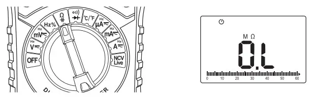
MEASURING RESISTANCE
- Turn the rotary dial to the
 setting.
- Insert the red test lead into the “Input” jack and the black test lead into the “COM” jack.

- Place the test leads at both ends of the resistance to be
measured and maintain strong contact. - The results will appear on the LCD display.

RESISTANCE NOTES:
- Do not change the resistance while taking measurements.
Doing so may damage the Meter and affect the test results. - Do not directly measure the internal resistance of micrometers, galvanometers, batteries, and other instruments.
- Do not test parallel circuits. The accuracy of the measurement will be affected, and the results may not be accurate.
- If the measured value is equal to the nominal resistance of the resistor or within the range of error, the resistor is functioning correctly.
- If there is a large deviation between the nominal resistance and the measured resistance, the resistor is bad.
- If the measured resistance is infinite (open circuit), zero (short circuit), or unstable, it means the resistor is damaged and can no longer be used.
MEASURING CAPACITANCE
- Turn the rotary dial to thesetting. Press the “FUNC” button to switch to Capacity Test.
- Insert the red test lead into the “Input” jack and the black test lead into the “COM” jack.

- Make a secure connection between the test leads and both ends of the capacitor.
- Measurement results will be displayed on the LCD display.

CONTINUITY TEST
- Turn the rotary dial to the
 setting.
 - Insert the red test lead into the “Input” jack and the black test lead into the “COM” jack.
- Place the test leads on both sides of the object to be measured.
If the value of the measured resistance or circuit is less than 300, the buzzer will emit a beep and the green indicator light will illuminate. When the value is between 300-600, the red indicator light will illuminate and the screen will display the measured value.
If there is no continuity, the buzzer will not sound, “OL” will appear on the screen, indicating infinite resistance.

DIODE TEST
- Set the function switch to “ ” range, Press the “FUNC” button to switch to diode Test.

- Connect the black test lead to the “COM” jack and the red test lead to the “INPUT” jack.
- Connecting the red test lead to the positive end of the diode and the black test leads to the negative end.
NOTE: Generally, the positive end of the diode is the longer end. - The LCD will show the reading of the voltage decreased by the diode. If the leads are incorrectly connected to the diode electrodes, the LCD will show “OL”.

TEMPERATURE MEASUREMENT
Set the function switch to the “ °C/°F” range.

- Insert the negative (-) plug of the K-type thermocouple to the COM jack and the positive (+) plug to the INPUT jack.

- Carefully touch the end of the thermocouple to the object being measured.
- Celsius and Fahrenheit are both displayed.

NOTE: Results take time to stabilize as thermal equilibrium is reached with the measuring environment. When the thermocouple is not in contact with an object being measured, it will read the ambient temperature of the surrounding environment.
NON-CONTACT VOLTAGE (NCV)
- The NCV function detects AC voltage without the use of test leads.

- Set the Rotary Dial to the NCV function NCV/Live
- When the meter senses a weak AC signal, the green indicator light will turn on and the buzzer emits a slow beep; When the meter senses a strong AC signal, the red indicator light will turn on, and the buzzer will emit a quick beep.
NOTE: This function does not affect the Meter’s measurement after exiting the setting. If the range switch is not in the NCV position, the Meter will operate normally.

LIVE WIRE DETECTION
- Turn the rotary dial to the NCV/Live setting.
Press the “FUNC” button to switch to Live Wire Detection and the screen will show “Live”.
- Insert the red test lead into the “Input” jack. Do not insert the black test lead into any terminal.

- Touch the point to be measured with the tip of the red test lead.
- When the meter senses a weak AC signal, the green indicator light will turn on, and the buzzer emits a slow beep; When the meter senses a strong AC signal, the red indicator light will turn on, and the buzzer will emit a quick beep.


GENERAL TECHNICAL INDICATORS
| Operating Environment |
|
| Storage Environment |
|
| Maximum Voltage |
|
| Fuse Protection |
|
| Sampling Speed |
|
| Display |
|
| Overload Indication |
|
| Low Battery Indication |
|
| Polarity Indication |
|
| Power |
|
TROUBLESHOOTING
| The reading does not stabilize |
|
| Reading is not accurate |
|
| A certain range is not available |
|
| Range error is large |
|
| No reading |
|
DC VOLTAGE
| Range | Resolution | Accuracy |
| 600mV | 0.1mV | ±(0.5% rdg +3 dgts) |
| 6V | 0.001V | |
| 60V | 0.01V | |
| 600V | 0.1V | |
| 1000V | 1V |
- Input Impedance: 10M0
- Overload Protection : 1000V DC/750V AC
AC VOLTAGE
| Range | Resolution | Accuracy |
| 600mV | 0.1mV | ±(0.8% rdg +5 dgts) |
| 6V | 0.001V | |
| 60V | 0.01V | |
| 600V | 0.1V | |
| 750V | 1V |
- Input Impedance: 10MΩ
- Overload Protection: 1000V DC/750V AC
- Frequency Range: 40Hz ~ 1kHz
- Response: True RMS
DC CURRENT
| Range | Resolution | Accuracy |
| 600pA | 0.1 pA | ± (1 .2% rdg +3 dgts) |
| 6000pA | 1 pA | |
| 60mA | 0.01 mA | |
| 600mA | 0.1mA | |
| 10A | 0.01A |
- Overload Protection: “A/mA”: F600mA/250V fuse “10A”: F10A/250V fuse
- Max.Input Current: “A/mA” jack: 600mA “10A” jack: 10A (For measurements>5A: duration <10 seconds, interval >15 minutes)
AC CURRENT
| Range | Resolution | Accuracy |
| 600pA | 0.1 pA | ± (1 .5% rdg +3 dgts) |
| 6000pA | 1 pA | |
| 60mA | 0.01 mA | |
| 600mA | 0.1mA | |
| 10A | 0.01A |
- Overload Protection: “A/mA”: F600mA/250V fuse “10A”: F10A/250V fuse
- Max.Input Current: “A/mA” jack: 600mA “10A” jack: 10A
- Frequency Range: 40Hz ~ 1KHZ
- Response: True RMS (For measurements>5A: duration <10 seconds, interval >15 minutes)
RESISTANCE
| Range | Resolution | Accuracy |
| 6000 | 0.10 | ±(1.0% rdg +3 dgts) |
| 6k0 | 0.001k0 | |
| 60k0 | 0.01k0 | |
| 600k0 | 0.1k0 | |
| 6M0 | 0.001M0 | ±(1.5% rdg +3 dgts) |
| 60M0 | 0.01M0 |
- Overload Protection: 250V
| Range | Resolution | Accuracy | |
| ℃ | 1℃ | -20℃~ 0℃ | ±5.0% rdg or±3℃ |
| 0℃ ~ 400℃ | ±1.0% rdg or±2℃ | ||
| 400℃ ~ 1000℃ | ±2.0% rdg | ||
| ℉ | 1℉ | -4℉~ 32℉ | ±5.0% rdg or±6℉ |
| 32℉~ 752℉ | ±1.0% rdg or±4℉ | ||
| 752℉~ 1832℉ | ±2.0% rdg | ||
- The accuracy does not include the error of the thermocouple probe.
CAPACITANCE
| Range | Resolution | Accuracy |
| 10nF | 0.001nF | ±(4.0% rdg +5 dgts) |
| 100nF | 0.01nF | |
| 1000nF | 0.1 nF | |
| 10pF | 0.001 pF | |
| 100pF | 0.01 pF | |
| 1000pF | 0.1 pF | |
| 10mF | 0.001mF | ±(5.0% rdg +5 dgts) |
| 100mF | 0.01mF |
- Overload Protection: 250V
FREQUENCY/DUTY CYCLE
| Range | Resolution | Accuracy |
| 10Hz | 0.001Hz | ±(1.0% rdg +3 dgts) |
| 100Hz | 0.01Hz | |
| 1000Hz | 0.1Hz | |
| 10kHz | 0.001kHz | ±(1.0% rdg +3 dgts) |
| 100kHz | 0.01kHz | |
| 1000kHz | 0.1kHz | |
| 10MHz | 0.001MHz | ±(3.0% rdg +3 dgts) |
| 1~99% | 0.1% |
- Measuring range: 0~ 10MHz
- Voltage range: 0.2~10V AC (the higher the measured frequency, the higher the voltage should be)
- Overload Protection:250V
NOTE:
![]() and, V
and, V![]() Frequency measurement:
Frequency measurement:
- Measuring range: 0 ~ 10kHz
- Voltage range: 0.5~600V AC (the higher the measured frequency, the higher the voltage should be)
- Overload Protection: 250 V
![]() ,
, ![]() and
and![]() Frequency measurement:
Frequency measurement:
- Measuring range: 0 ~ 10 kHz
- Signal range; ≥ 1/4 range (the higher the measured frequency, the higher the current should be)
- Overload Protection: “A/mA”:F600mA/250V fuse “10A”: F10A/250V fuse
DIODE AND CONTINUITY
| Range | Introduction | Remark |
| The approximate forward voltage Drop will be displayed. | Test voltage: 3.0V Overload Protection:250V | |
| If the value of the measured resistance or circuit is less than 30Ω, the buzzer will emit a beep and the green indicator light will illuminate. When the value is between 30Ω~60Ω, the red indicator light will illuminate, and the screen will display the measured value. If there is no continuity, the buzzer will not sound, “OL” will appear on the screen, indicating infinite resistance. | Test voltage: 1V Overload Protection: 250V |
MAINTENANCE
CLEANING THE METER:
If there is dust or humidity in the terminals, it may produce erroneous measurements. Please clean the Meter as follows:
- Turn of the power to the Meter and remove the test leads.
- Wipe the case with a damp cloth or mild detergent. Do not use abrasives or solvents. Wipe the contacts in each terminal with a clean cotton swab dampened in alcohol.
REPLACING THE BATTERY AND FUSE
BATTERY REPLACEMENT:
- Turn off the Meter and remove the test leads.
- Remove the screws on the battery cover with a screwdriver, and remove the cover.
- Remove the old battery and replace it with a new battery of the same specification. Please pay attention to the polarity of the battery. The positive and negative polarity of each battery is marked in the battery box.
- Put the battery cover back to its original position and fix the battery cover with the removed screws.
REPLACING FUSES:
Fuses rarely need to be replaced and are usually blown due to operator error. To replace the fuses:
- Disconnect the test leads.
- Remove the rubber sleeve and screws on the back cover of the Meter.
- Open the back of the Meter and replace it with fuses of the same rating.
It is crucial that the replacement fuses have the same rating:
Fuse 1: F600mA/250V fuse,6mmX32mm
Fuse 2: F10A/250V fuse,6mmX32mm
INCLUDED INBOX
- 1 x Owner’s Manual
- 1 x Pair of Test Leads
- 1 x K-Type Thermocouple
- 1 x AstroAI 6000 Counts Multimeter
3 YEAR WARRANTY LIMITED WARRANTY FROM ASTORIA
Each AstroAI Digital Multimeter will be free from defects in material and workmanship. This warranty does not cover fuses, disposable batteries, and damage from neglect,
misuse, contamination, alteration, accident, or abnormal conditions of operation or handling, including overvoltage failures caused by use outside the Multimeter’s specified
rating, or normal wear and tear of mechanical components. This warranty covers the original purchaser only and is not transferable.
If this product is defective, please contact AstroAI Customer Support at [email protected].
![]()
Web:WWW.astroai.com
E-mail:s[email protected]
Documents / Resources
 | AstroAI True RMS 6000 Count Digital Multimeter [pdf] User Manual AstroAI, True, RMS, 6000 Count, Digital, Multimeter |


