83.00
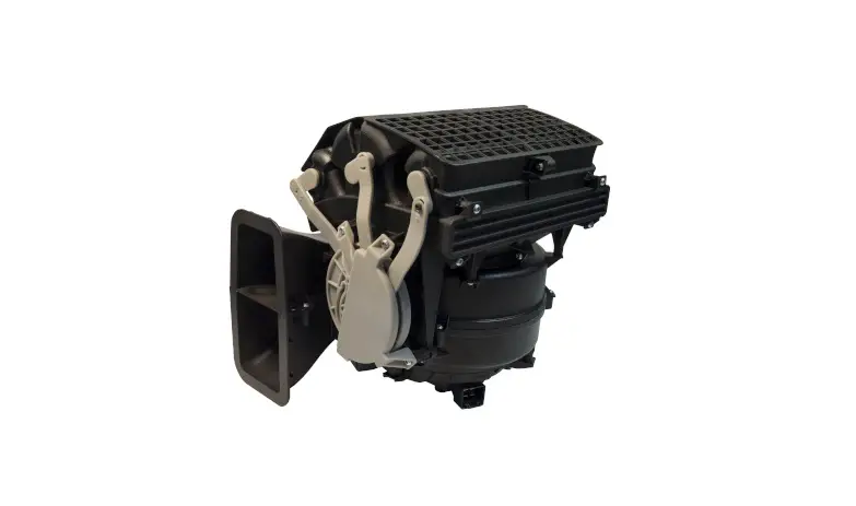
Cab Heater and Air Conditioner, Valeo
Troubleshooting
| Recirculation Door Actuator Circuit Tests | ||||
| Test | Conditions | Test Point | Good Result | What to Do if Test Fails |
| actuator motor drive circuit | key on, engine off recirculation door actuator connector removed fan (blower) speed on low change the recirculation setting while observing the digital multimeter (DMM) | Measure across pins 5 and 6 of the recirculation door actuator connector. | 9V+ for about 1 second* | Check wiring between control head and recirculation door actuator. If wiring is okay, replace the control head. |
| actuator position sensor reference voltage circuit | key on, engine off recirculation door actuator connector removed | Measure between pin 10 of the recirculation door actuator connector and the battery negative post. | 5V | |
| actuator position sensor reference ground circuit | key on, engine off recirculation door actuator connector removed | Measure between pin 8 of the recirculation door actuator connector and the battery positive post. | 12V* | |
| actuator position sensor feedback signal circuit | key on, engine off all connectors connected | Backprobe pins All and B5 at control head connector. | 0.8V (recirc. on) to 4.7V (recirc. off) | Check wiring between control head and recirculation door actuator. If wiring is okay, replace the actuator. |
* The voltage should be approximately the same as the battery voltage.
† It is assumed that reference voltage and ground circuits are functioning.
Table 5, Recirculation Door Actuator Circuit Tests
Blower Motor Circuit Tests
The blower motor power and ground are supplied directly to the blower motor assembly. The blower speed is controlled by the fan switch on the control head (climate control panel). The control head sends a pulse width modulated (PWM) signal to the blower motor. The frequency of this signal is 2000 Hz. The pulse width varies with the fan switch selection.
The protection modes for the blower motor are as follows:
- Reverse Voltage Protection—The motor will not operate if the polarity of the motor leads, cir-cuits 98F and ground, are reversed.
- Current Protection—If the motor exceeds the maximum limit, the speed will be reduced until the current is within the limits (23.5A maxi-mum).
- Temperature Protection—If the motor’s internal temperature sensor senses that the temperature is too high, the blower speed is reduced to 1000 rpm to reduce the load on the motor and a comparison is made between the sensor reading and the maximum limit. If the temperature is still too high, the blower speed is further reduced to the minimum value of approximately 500 rpm and a temperature comparison is made to the maximum. If, after the second comparison, the temperature is still too high, the motor will shut down until it has cooled sufficiently.
Perform the tests in Table 6 in the sequence presented. The directions under the column “What to Do if Test Fails” are sometimes dependent on good results from previous tests. If any of the tests fail, stop and perform the specified repair or check. If the blower motor passes the tests in Table 6 and the blower still does not operate properly, check the blower motor. To quickly check for normal operation, set the fan switch to high and listen for a change in the sound of the blower near the HVAC unit while pressing the recirculation button on and off. The blower will be louder when recirculation is enabled.
| Blower Motor Circuit Tests | ||||
| Test | Conditions | Test Point | Good Result | What to Do if Test Fails |
| main power to blower motor | battery switch on (if equipped) key off blower motor connector removed | Measure between pin 4 of blower motor connector and negative battery post. | 12V* | Check fuse F2 in the PDM under the hood. If the fuse is blown, check for shorted wiring or a damaged blower motor. Check for an open in circuit 98F |
| blower motor ground circuit | battery switch on (if equipped) key off blower motor connector removed | Measure between pin 3 of blower motor connector and the positive battery post. | 12V* | Check for an open in blower motor ground circuit. |
| PWM signal from control head | battery switch on (if equipped) key on, engine off blower motor connector connected change the fan (blower) speed setting on the control head and observe frequency using the digital multimeter (DMM) | Backprobe pins 4 and 5 of the blower motor connector, harness side (DMM set to measure frequency). | 0 Hz fan off 0 Hz fan on high 2000 Hz all other speeds | Check circuit 338H. Check control head. |
| voltage drop (power circuit) | battery switch on (if equipped) key on, engine off all connectors connected fan (blower) speed on high | Backprobe pin 4 at the blower motor connector, other lead on positive battery post. | less than 0.5V | Locate high resistance or open in circuit 98F |
| voltage drop (ground circuit) | battery switch on (if equipped) key on, engine off all connectors connected fan (blower) speed on high | Backprobe pin 3 at the blower motor connector, other lead on negative battery post. | less than 0.5V | Locate high resistance or open in blower motor ground circuit. |
| blower motor current draw | battery switch on (if equipped) key on, engine off all connectors connected fan (blower) speed on high | Use current clamp around circuit 98F or blower motor ground wire. | less than 23.5A | Check blower motor. |
* The voltage should be approximately the same as the battery voltage.
Table 6, Blower Motor Circuit Tests
Evaporator Probe Circuit Tests
The evaporator temperature sensor is a resistive ele-ment, where the resistance increases as the temperature decreases. The control head (climate control panel) uses this sensor to determine the evaporator temperature. The control head uses the temperature information to determine if the A/C compressor
Business Class M2 Workshop Manual, Supplement 25, March 2014
300/13


