DANCOVER LH-100 USB Port for Electric Scooter Bicycle Tricycle Instruction Manual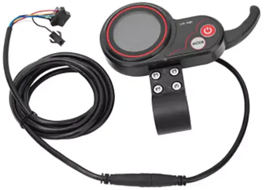
Important information!
NB! This product is not approved to be driven on public roads.
Only to be used on private land.
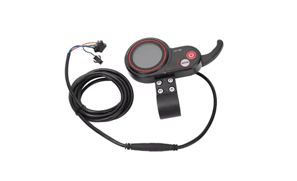
Product specification
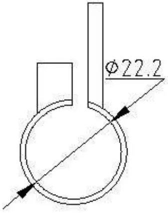
The shell of the product is ABS. The transparent window is crystal with high hardness acrylic, hardness value is equivalent to toughened glass.
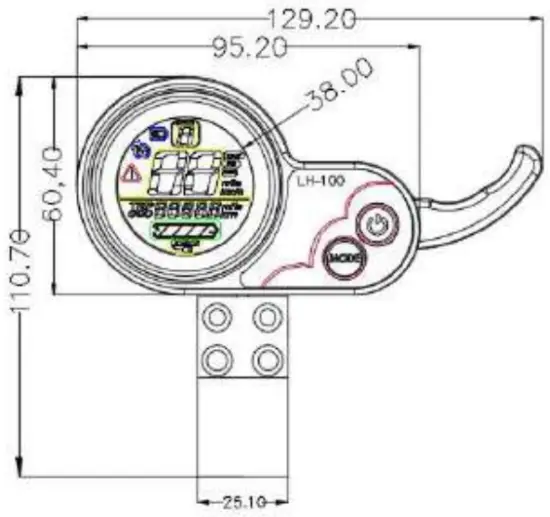
- Elevation

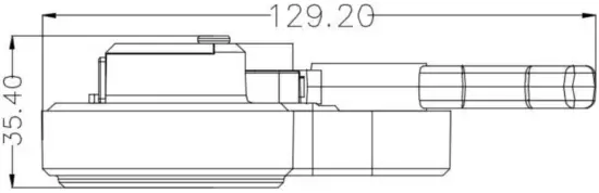
- Side elevation

- The support of LH-100

Working Voltage and the Mode of Connection
- Working Voltage: DC24V/36V/48V(display choose by itself) And we also can set the voltage.
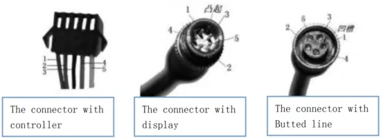
- Mode of connection Standard connection

The line number The color of the line Function 1 Red(VCC) The power of the display 2 Blue(K) The power of the controller 3 Black(GND) Earth line of display 4 Green(RX) The data acceptance line of display 5 Yellow(TX) The data transmission line of display Some display use waterproof plug-in components, so it can’t see the color of the line.
Function
Show content:
The content of speed, power, hitch, Total mileage ,Single mileage
The function of control and setting:
Controller the switch power, Wheel diameter setting, Idle automatic sleep time setting, Backlight setting, Startup mode setting, Drive mode setting, Voltage level setting, Controller Current Limit Setting, USB charging function
Communicating Protocol: URAT
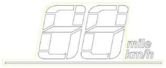
All content on display(power on within 1 second)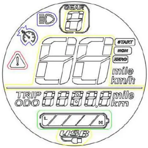
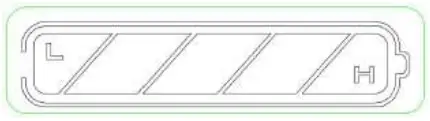
- Voltage level

- Multifunctional display area

Total mileage ODO、 Single mileage TRIP、 Digital voltage display VOL、 Fault code ERRFault code (decimal system)
fault condition remarks 0 Normal status 1 keep 2 brake 3 PAS sense hitch (Riding sign) Not implemented here 4 6KM/H cruise 5 Real-time cruise 6 Battery under voltage 7 Motor fault 8 Turnstile fault 9 Controller fault 10 Communication receiving fault 11 Communication transmission failure 12 BMS communication failure 13 Headlamp failure - Speed display area

Unit: MPH, KM/H
The speed signal is taken from the Hall signal inside the motor. Sent to controller by controller(Time of single Hall period,unit:1MS).The display calculate the true speed based on wheel diameter and signal data calculate the true speed(The motor Holzer also needs to set the number of magnetic steel) - Vehicle power gear adjustment,
 0-9 digital display;
 - vehicle status display area

Zero start and non-zero start prompt
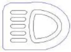
The headlight turns on the prompt;
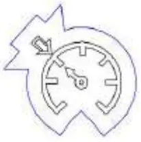
Constant speed cruise hint;
Communication fault prompt;
USB charging hint

 0-9 digital display;


Setting
P01: Backlight brightness: The 1 level is the darkest, Level 3 brightest ;Default: 3
P02: Mileage: unit,0:KM;1:MILE;Default: KM
P03: Voltage level: 24V,36V,48V,52V,60V, Default:52V
P04: Dormancy time:0 means no dormancy; Other numbers are dormant time. The rangeis1 60 minute.Default:5
P05: Reserve
P06: Wheel diameter: The unit is inch. The accuracy is 0.1; Default:10.0
P07: Speed measuring magnetic steel number. The range is 0-255. Default:28
P08: Rate-limiting: The range is 0-100km/h. Default: 100
P09: Zero start、 no zero start setting;0 means zero start.1means no Zero start. Default: 0
P10: Reserve
P11: EABS switch choose. The range is 1-5.0 means closing.1 means weakest.2 means strongest. P12: Soft and hard start strength. The range is 1-5. The softest is 1.The hardest is 5.Default: 3
P13: Reserve
P14: Reserve
P15: Controller under-voltage
P16: ODO Zero setting: keep pressing + for 5 seconds, ODO will zero clearing.
P17: When it shows 0,it can not use cruise. When it shows 1,it can use cruise.Default:0
P18: Reserve
P19: Reserve
P20: Communication protocol is defaults 4.It can not change.
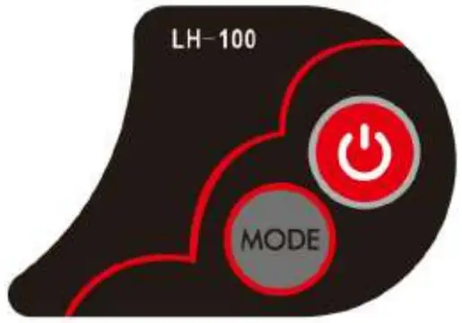
- When it is shutdown, long-time pressing
 to turn on the power. When it is power on ,It can change interface between the ODO、TRIP、VOL, by pressing for short time.
 - When it is power on, long-time pressing to turn off, short-time pressing can change gear.
- Long-time pressing and
 can get into the menu to change the interface.
 - Get into the setting interface, short-time pressing can change parameter. Short-time pressing or long-time pressing can add or reduce the numerical value. After
changing, short-time pressing to change the next numerical value. After
changing, long-time pressing and to get out of the interface, or waiting8seconds,it can save the numerical value and drop out by itself.
Crankshaft regulating motor speed by Up and down, Motor speed increase; relax hand it return to zero.
Contact information | |
| Head office: Dancover NS Lyngevej 16A, Non–e Herlev 3400 Hillerod Denmark | For more information please visit: |
| National contact | |
| Denmark: [email protected] | Spain: [email protected] |
| UK: [email protected] | Italy: [email protected] |
| Germany: [email protected] | Switzerland: [email protected] |
| France: [email protected] | Austria: [email protected] |
| Sweden: [email protected] | Norway: [email protected] |
| Finland: [email protected] | Nederland: [email protected] |
| Poland: [email protected] | Ireland: [email protected] |
| Luxembourg: [email protected] | Belgium: [email protected] |
| Portugal: [email protected] | |


