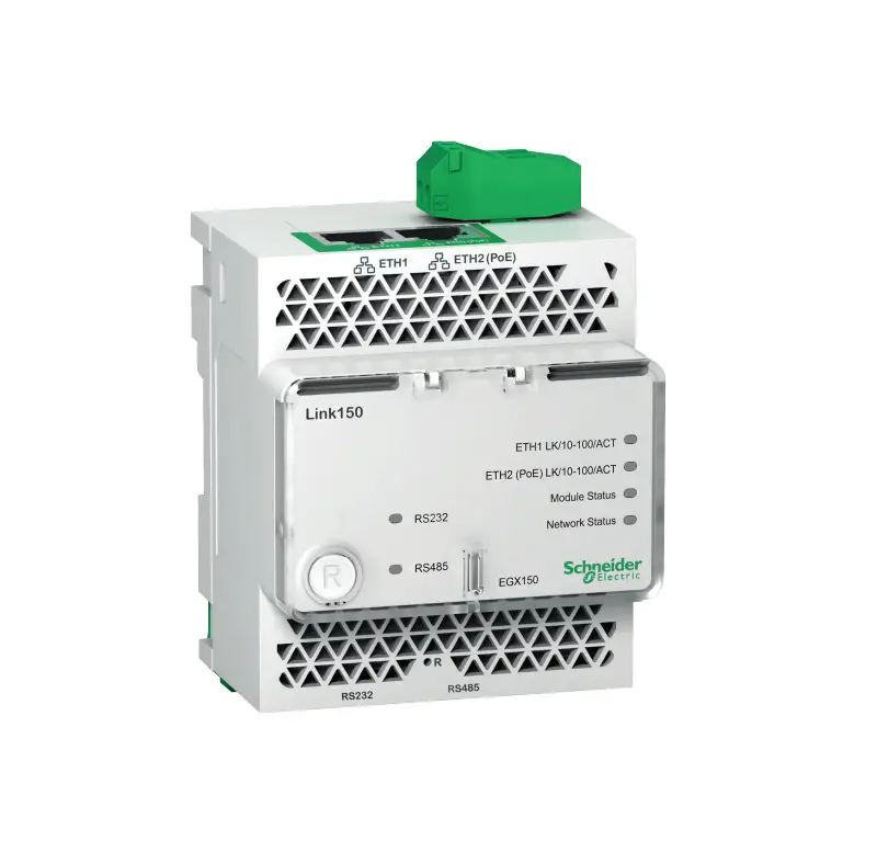
Schneider Electric EGX150 Ethernet Gateway
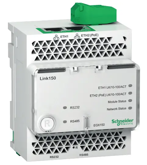
Ethernet Gateway
![]() DANGER
DANGER
HAZARD OF ELECTRIC SHOCK, EXPLOSION OR ARC FLASH
- Apply appropriate personal protective equipment (PPE) and follow safe electrical work practices. See NFPA 70E, CSA Z462, NOM-029-STPS or local equivalent.
- Turn off all power supplies to this device and equipment in which it is installed before working on the device or equipment.
- Always use a properly rated voltage sensing device to confirm that all power is off.
- Do not exceed the device’s rating above specified maximum limits.
- Connect protective ground (earth) before turning on any power supply to this device.
Failure to follow these instructions will result in death or serious injury
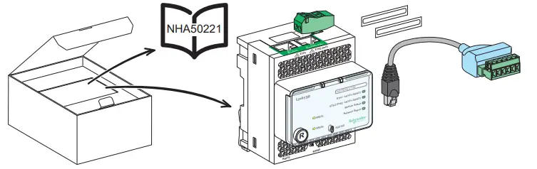
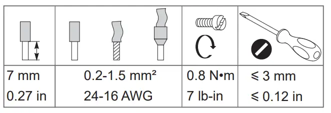
Required for Installation

Description
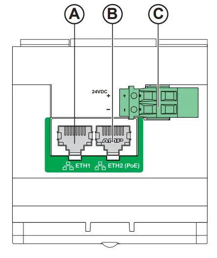
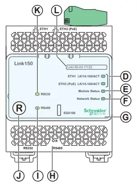
A ETH1: Ethernet 1 communication portB ETH2: Ethernet 2 (Power over Ethernet) communication portC 24 Vdc power supply terminal blockD Ethernet communication LEDs:
- yellow: 10 Mbps
- green: 100 Mbps
E Module status LED:
- steady off: no power
- steady green: device
operational
- steady red: out of service
- flashing green: firmware corrupted
- flashing red: degraded mode
- flashing green/red: self-test
F Network status LED:
- steady off: no power / no valid IP address
- steady green: connected, valid IP address
- steady amber: error in IP configuration / default IP address
- steady red: duplicated IP address
- flashing green/red: Self-test
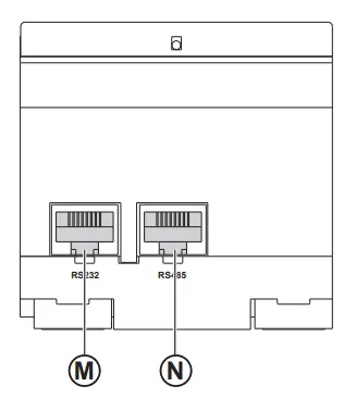
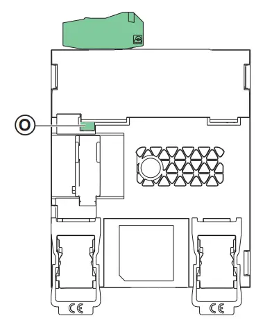
G H IP reset buttonI RS485 traffic status LEDJ Device soft restart button (accessible closed cover)K RS232 traffic status LEDLDevice name labelM RS232 portN RS485 portO Grounding connection
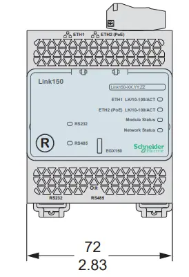
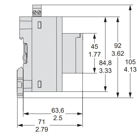
Dimensions
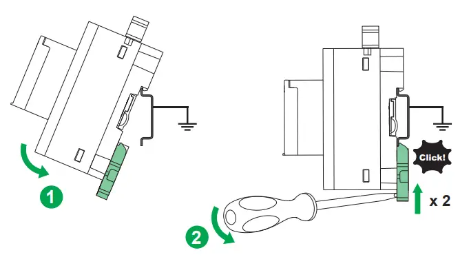
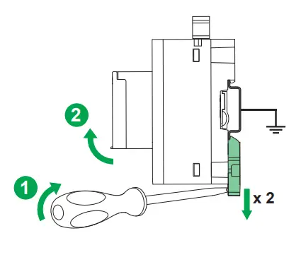
Installation
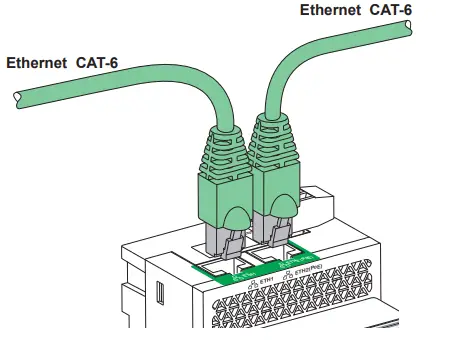
Power Supply and Ethernet Connection
24 Vdc and Ethernet Connection
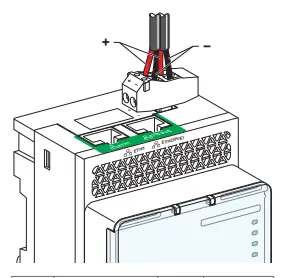
![]() The Link150 can be powered by 24 Vdc or Power-over-Ethernet (PoE)
The Link150 can be powered by 24 Vdc or Power-over-Ethernet (PoE)
Ethernet Switch with Endspan PoE ports
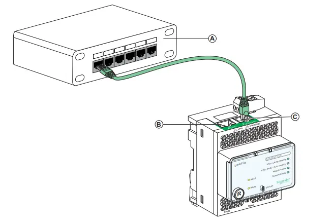
A Ethernet Switch with Endspan PoE portsB Ethernet 1 communication portC Ethernet 2 (PoE) communication port
Ethernet Switch with Midspan PoE ports
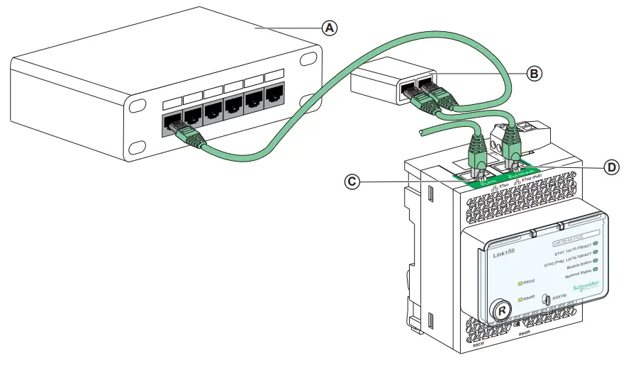
A Ethernet SwitchB Midspan PoE InjectorC Ethernet 1 communication portD Ethernet 2 (PoE) communication port
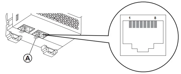
Serial Connection
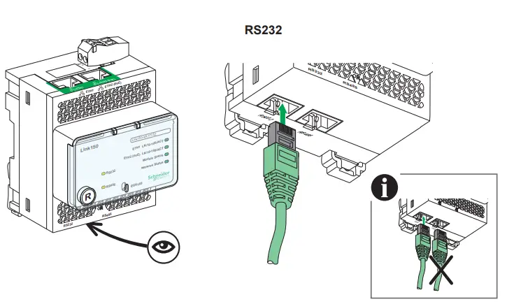
RS232 Wiring
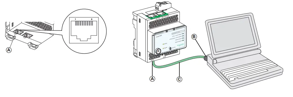
A RS232 serial port (See table below for pin-outs)B RJ45 to DB9C RJ45 crossover cable
| Pin No. | Signal Name | <m) Description |
| 1 | DSR / RI | Data Set Ready/ Ring Indicator |
| 2 | DCD | Data Carrier Detect |
| 3 | DTR | Data Terminal Ready |
| 4 | SGND | Signal Ground |
| 5 | RX | Receive Data |
| 6 | TX | Transmit Data |
| 7 | CTS | Clear To Send |
| 8 | RTS | Request To Send |
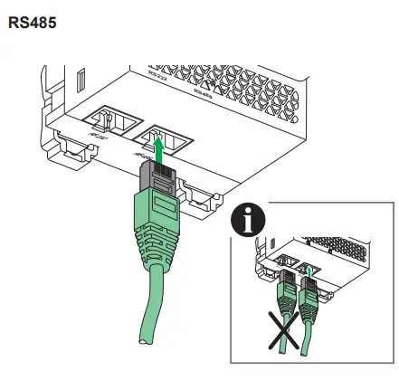
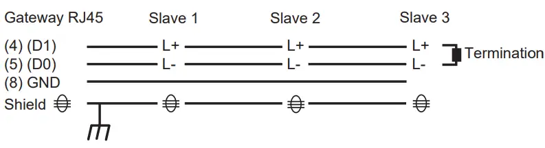
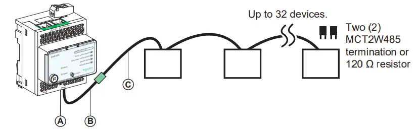
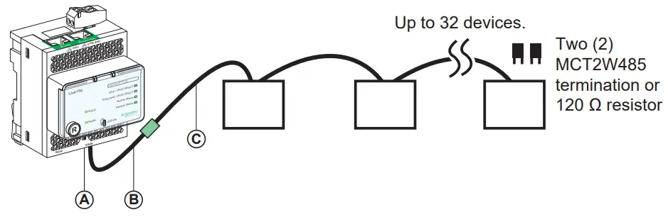
RS485 2-Wire
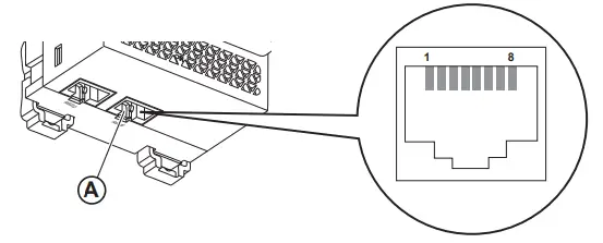
Connection pin-out for RS485 2-wire mode
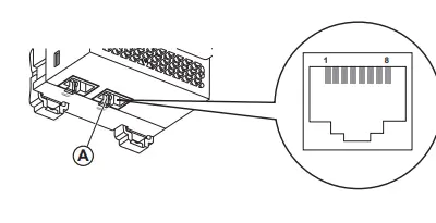
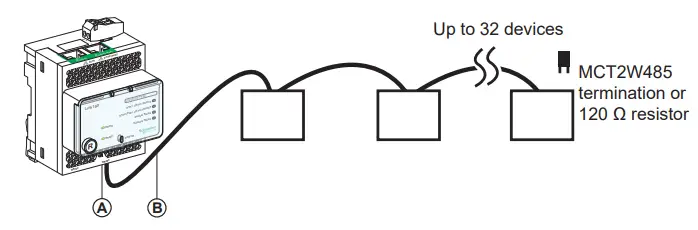
A RS485 serial portB RJ45 cable
A RS485 serial portB Link150 cable adapter*C Belden 9841
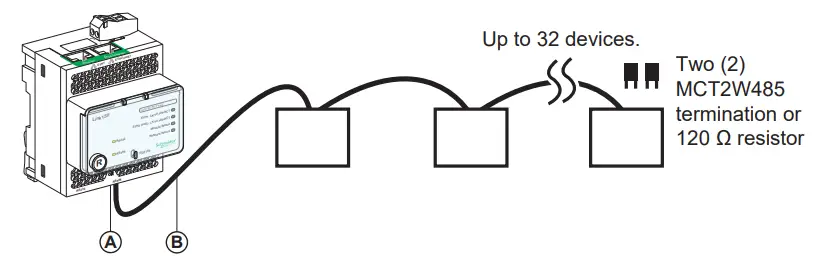
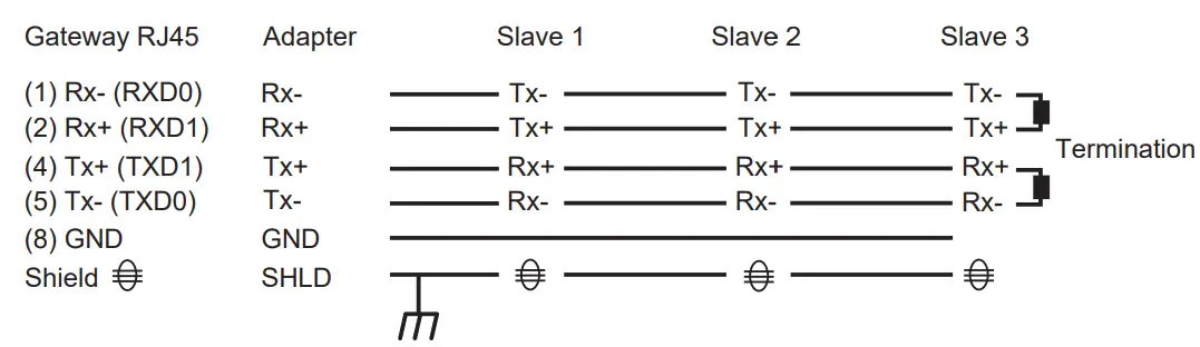
RS485 4-Wire
Connection pin-out for RS485 4-wire mode
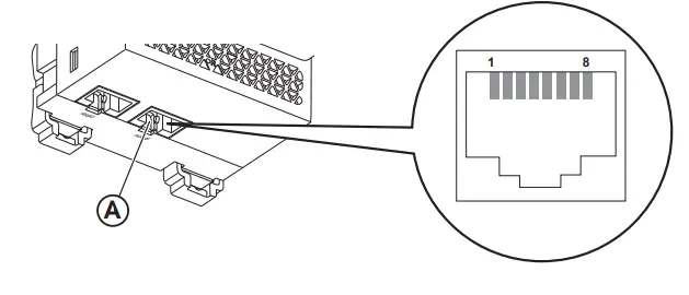
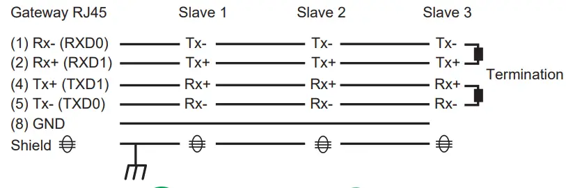
A RS485 serial portB RJ45 cable*
* VW3A8306D30 is an accessory for RJ45 connection.
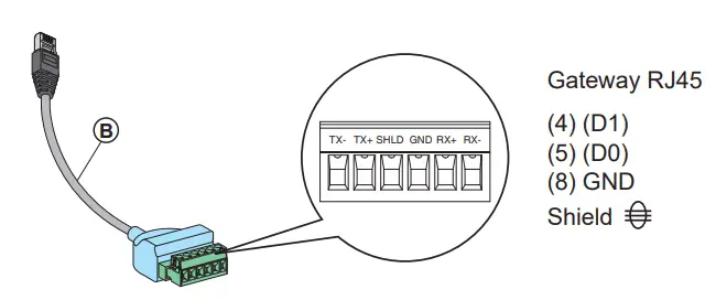
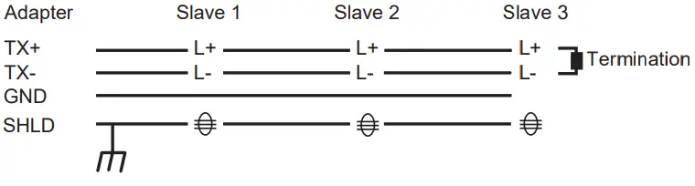
RS485 4-Wire with Link150 Cable Adapter
Connection pin-out for RS485 4-wire mode with Link150 cable adapter
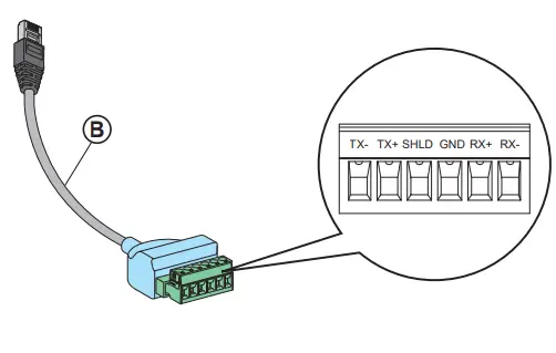
A RS485 serial portB Link150 cable adapter*C Belden 8723 or 9842
* PH68385 is an accessory for RJ45 connection.
NOTE: – The color code for Belden 8723 is Green (Tx+), White (Tx-), Red (Rx+), and Black (Rx-).
- The color code for Belden 9842 is Blue/White (Tx+), White/Blue (Tx-), Orange/White (Rx+), and White/Orange (Rx-)
Specifications
| <m) Control Power Input | |
| Power over Ethernet | Class 0 |
| Operating Input Range | 38.4 V to 57.6 V |
| Burden (actual) | 4W |
| Isolation | 1 kV |
Access the Link150 Web Pages for the First Time
The procedure to access the first time to Link150 webpages depends on the operating system of the computer:
- Windows Vista, Windows 7, Windows 10 or newer operating systems
- Windows XP or older operating systems.
Both the procedures are described in the Link150 user guide. The references of the Link150 guides are available in the list of related documents (see page 1)
 Ethernet Gateway Link150

 DECOA 110EN
![]() WARNING: Cancer and Reproductive Harm www.P65Warnings.ca.gov
WARNING: Cancer and Reproductive Harm www.P65Warnings.ca.gov

Retain instruction sheet for future use.
Visit our website at www.se.com
to download the documents listed above (user guides ) and other documents.
PLEASE NOTE
- Electrical equipment should be installed, operated, serviced, and maintained only by qualified personnel.
- All pertinent state, regional, and local safety regulations must be observed when installing and using this product.
- No responsibility is assumed by Schneider Electric for any consequences arising out of the use of this material.


Schneider Electric Industries SAS
35, rue Joseph Monier
CS 30323
F – 92506 Rueil Malmaison Cedex
www.se.com

Schneider Electric Limited
Stafford Park 5
Telford, TF3 3BL
United Kingdom
www.se.com/uk
© 2021 Schneider Electric – All rights reserved.


