Robert Bosch Engineering Business Solutions Private CU-41-3U-CM-PS1 iTraMS CCU
Introduction
Intelligent Transport Management System (iTraMS) CCU is a telematics platform solution that provides transportation solutions to OEMs.
Objective
The purpose of this document is to set out for the customer information and requirements for what, according to our opinion, may be considered a proper and correct installation. Please note that Bosch does not assume any liability for the information/recommendations set out herein and that responsibility for the proper installation solely rests with the customer.
General
All efforts have been made to ensure the accuracy of material provided in this document at the time of release. However, the items described in this document are subject to continuous development and improvement. All specifications are subject to change without notice and do not represent a commitment on the part of Robert Bosch Engineering and Business Solutions Private Limited (RBEI). RBEI will not be responsible for any loss or damages incurred related to the use of information contained in this document.
Before starting up, connecting, and operating this product it is essential that the installation instructions and, in particular, the safety instructions are studied carefully. By doing so, any uncertainties in handling this product can be eradicated and will ultimately help avoid damage to the device.
FCC Compliance Notification to User
These devices comply with Part 15 of the FCC Rules. Operation is subject to the following two conditions: (1) these devices may not cause harmful interference, and (2) these devices must accept any interference received, including interference that may cause undesired operation.
Co-Location Warning Statement
These devices and their antennas must not be co-located or operating in conjunction with any other antenna or transmitter.
Exposure Compliance
Do not touch the Primary antennas, which are transmitting RF signals. Always disconnect power to the CCU before installation or maintenance service. The Primary antennas should always be separated from the operator or nearby person by a minimum distance of 20 cm.
Information to User:
These devices must be operated as supplied by RBEI. Any changes or modifications made to these devices without the express written approval of RBEI may void the user’s authority to operate these devices.
Disclaimer
iTraMS functionalities cannot be guaranteed if the stated instructions are violated. This includes handing by untrained person, using the wrong connector, etc. This product is not intended for use in life-support appliances, devices, or systems where a malfunction of the product can result in personal injury. RBEI customer using, integrating, and/ or selling this product for use in such appliances do so at their own risk and agree to fully indemnify RBEI for any resulting from incorrect use or illegal sale.
WARNING: This device has been approved to use in the industrial circumstance (office use), there is possibility to have electro-magnetic interference if it is used in home
Copyright
The information in this document should not be altered or amended without special notification from Robert Bosch Engineering and Business Solutions Private Limited (RBEI). RBEI undertakes no further obligation in relation to this document. RBEI or RBEI- Approved Service Personnel can only use the product described in it. Under no circumstance may any part of this document be copied, reproduced, transmitted, stored in a retrieval system, or translated into another language without the express written permission of RBEI.
©Copyright© 2020 Robert Bosch Engineering and Business Solutions Private Limited. The names and designations used in this document are trademarks or brands belonging to the respective owners.
Agreed Product Use
The intended and non-intended use of iTraMS CCU product is discussed in the below sections.
Intended Use
RBEI will be responsible for delivered products being fit for use of purpose intended and/or having a defined level of quality, such responsibilities are subject to the application of the product conforming to the agreed upon environment, installation and stress conditions, as such are referenced in the attached specification.
When the product during the Bosch release procedures has successfully met the testing specifications agreed to the Customer, it is deemed to fully cover all requirements, if any, that the product be fit for the use or purpose intended and/or have a defined level of quality. Customer shall be responsible for the system application, which includes ensuring that the intended product application and all environmental, installation and stress conditions to which the product will be exposed are covered by such testing. Customer shall be responsible for making sure that the product will not be exposed to conditions in excess of those referenced in such testing specifications. The conditions of use (environment, application, installation and loads) contained in this manual and associated agreed documents constitute the scope of the product’s suitability for its contractually required, intended or ordinary use and the scope of the product’s condition/ quality. The customer is responsible for ensuring the product’s usability in the vehicle.
The product is intended for and is undergoing approval for installation and operation in automobiles, commercial vehicles, off-highway vehicles and coaches with a rated voltage of 12(24) volts. It may be necessary to adapt the product’s factory-set state to suit the specific country.
Only connecting cables and external devices that are appropriate for the device in question as regards safety, electromagnetic compatibility and grade of shielding may be used. Compliance with the applicable standards cannot be guaranteed if the device is modified without the agreement of Bosch.
Bosch is only responsible for implementing the device side connector (interface) according to the customer’s specifications. Bosch does not assume any responsibility and does not provide any guarantee for the plug-in connection in particular for its electrical functioning, durability and imperviousness since this is applied by request of the customer.
If, in order to connect the device, ignition and battery are bridged, the device will draw the full operating current even when switched off. In this case, without any further deactivation on the vehicle-side, there is a risk of battery depletion. No liability is assumed for any damage occurring because of this. Do not cover ventilation openings and heat sinks otherwise a build-up of heat may occur in the device that could lead to malfunction. There are no specific ventilation openings or heat sinks in CCU device, but mounting in a thermal capsuled environment should be avoided, as it will lead to an increase of the operating temperature.
Do not insert foreign bodies in the insertion slots or openings of the device otherwise injury or damage to the device may occur.
The device must not be exposed to hot or burning objects (e.g. cigarettes).
To clean the device, never use hard or sharp objects that could damage the protective pane or housing. Do not use aggressive cleaning agents such as thinners, benzene, abrasive cleaners, spray cleaners, acidic or alkaline solutions, or wax. Do not spray any liquids onto the device. To clean the housing moisten a soft cloth with tepid water and wipe off the dirt. Make sure that no liquid enters the inside of the housing. Afterwards, wipe the cleaned surface with a clean, dry cloth.
If the device is to be cleaned before installation in the vehicle, make sure the openings (in particular the connector contact points) are kept sealed so that no liquid can enter the device.
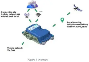
Overview
iTraMS is a platform for TCU or CCU that is an onboard system that controls wireless tracking, diagnostics and communication to/from the vehicle; these systems can be used for fleet management and vehicle tracking, among many others. This CCU has the following connectivity solutions:
- Wireless Connectivity
o Cellular 4G LTE / 3G WCDMA
o WLAN 802.11 b/g/n - Wired Connectivity
o CAN o RS485
o Ethernet
o USB2.0
Symbols Used
The document conventions used in this manual are in the sections below:
KEYWORD | FORMAT | DESCRIPTION |
| Warning | WARNING: Mismatch may damage the connector. | Possible impending danger. |
| Note | Note: The device should not be connected to any power supply during SIM installation | Record of points relevant to the topic |
Warranty and Service Clauses
For any of the products outside applications or environments outside the agreed may lead to damage or malfunctioning of the product specification, no warranty shall apply and product
Safety and Instructions
Do’s and Don’ts
- The different dos and don’t s to be followed while handling the device are as seen below:
- The CCU should not be opened or modified in any way. Doing so will void the warranty.
- Do not pour any liquid into any opening. It may lead to damage or malfunctioning of the product.
- The equipment is operable within the temperature range -40DegC to +95DegC.
Precautions for Installation
The product must be installed by skilled and instructed personnel only. Personnel scheduled to be trained, familiarized and instructed or to take part in a general training course may only work with the product under the supervision of an experienced person
- Electro Static Discharge (ESD) precautions should be taken while installation of CCU.
- The CCU should be installed on the vehicle in accordance to the instructions in the Installation manual. Refer to the annexure for guidelines.
- Follow the specifications and instructions of the vehicle manufacturer.
- During vehicle installation, switch the gearbox to neutral and actuate the hand brake. Secure the vehicle against rolling away with brake wedges.
- Switch off the ignition when you connect/disconnect the CCU to/from the OBDinterface.
- Do not drop the CCU. It may lead to damage or malfunctioning of the product.
- Install the CCU at a location that
o Does not impair any of the safety devices (such as the main airbag, knee airbag and steering).
o Does not impair the driver of his/her driving.
o At least 20 cm away from any human contact and fastened with sufficient space.
o Prevent any contact of the CCU, OBD connection cable or wiring harness with hot components.
o The functioning of other lines or cables is not impaired, or they are not clamped.
o The CCU should only be removed or replaced by an authorized service personal.
Scope for Delivery
The scope of delivery includes:
- On-board Unit (CCU)
- Installation Manual
- The voltage and current rating of the wiring harness must be greater than the voltage and current rating mentioned in the technical specifications.
- It is recommended to have a fast blow fuse with below rating in series on the positive power supply line at vehicle wiring harness.
- 5A for 12/24V applications
- If one of the following situations arise, get the equipment checked by service technician:
• The wiring harness or connector is damaged.
• Liquid has penetrated into the equipment.
• The equipment has been exposed to moisture.
• The equipment does not work as per specifications.
• The equipment has been dropped and damaged.
• The equipment has been exposed to elevated temperatures (beyond storage specifications).
Note: Check the product for any damages. Never use a damaged product. If you have any complaints, please contact the service technician.
Legal Requirements
iTRAMS CCU product family is undergoing Electromagnetic and Radio Frequency conformance tests and validations in different regions.
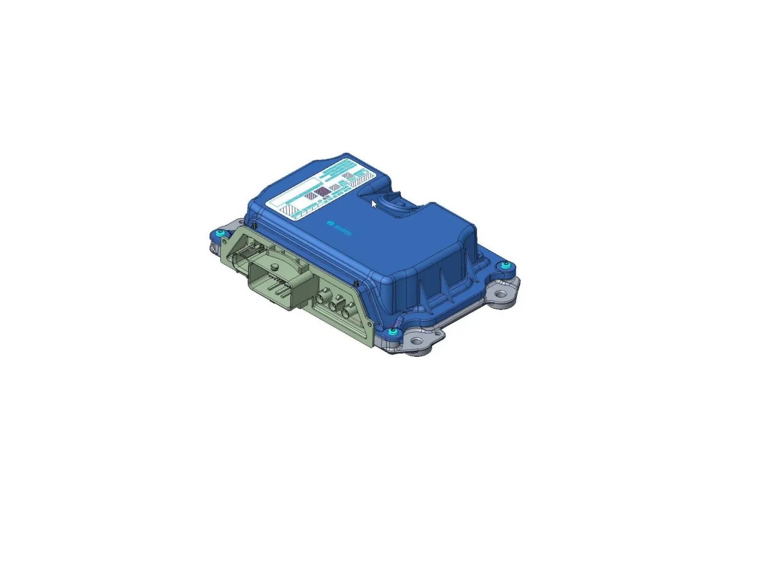
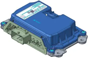
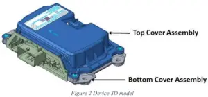
Device 3D Model
Installation
Installation of Cable Harness
- Suitable protective measures against electrostatic discharges are to be taken for persons and tools. In particular, CCU connector pins are not supposed to be touched.
- Liquids and other media are not allowed to come in contact with the connectivity unit connector and its pins.
- Plug the Cable harness cable into the CCU. Check the PIN numbers on the connector of the connecting cable.
- Make sure that it is connected to the same pin slots on the device side connector. Lock the connector.
- For a secure connection, the interlocking mechanism of the connector must not be damaged and must be in a completely closed state.
- It must be ensured that the connector from the wiring harness side is disconnected only in dry and clean conditions.
- Connection and disconnection procedure must be done in a particular sequence as given below:
- Connection sequence during installation
• Connect Antenna cables
• Connect main connector
• Connect HSAL Connector - Disconnection sequence
• Disconnect HSAL connector
• Disconnect main connector
• Disconnect Antenna cables
WARNING: Mismatch of the sequence may damage the connector
NOTE: Un-used connectors (either Antenna Ports or Wired Connectors) must be closed appropriately to meet the specified IP rating of the product.
Technical Specifications
a. Analog inputs
| ANALOG INPUTS | REMARKS |
| Number of inputs | 3 Analog inputs |
b. Digital inputs
| DIGITAL INPUTS | REMARKS |
| Number of Inputs | 5 digital inputs |
c. Digital Output
| DIGITAL OUTPUTS | REMARKS |
| Number of output | 1 programmable High Side output |
| Max continuous current | 450 mA |
| DIGITAL OUTPUTS | REMARKS |
| Number of output | 2 programmable Low Side outputs |
| Max continuous current | 450 mA of each output |
d. Bus (CAN0 and CAN1)
| Analog Inputs | REMARKS |
| Number of Interfaces | 2 CAN Interfaces |
| Connection | 2-wires (CANH-CANL) |
| Max Data rate | 500 Kbps |
e. Bus (RS485)
| Interfaces | REMARKS |
| Interface | RS485 Interfaces |
| Connection | 2-wires (D+ & D-) |
| Max Data rate | 115.2Kbps |
f. Bus (Ethernet)
| Interfaces | REMARKS |
| Interface | Ethernet 10base T, 100Base TX |
| Connection | 4-wires (RX+, RX-) & (TX+, TX-) |
| Max Data rate | 10Mbps & 100Mbps |
g. Bus (USB2.0)
| DIGITAL OUTPUTS | REMARKS |
| Number of output | 1 programmable High Side output |
| Max continuous current | 450 mA |
h. Internal Memory
| Memory Type | REMARKS |
| Flash Memory | eMMC, 8 GB |
i. Power Requirements
| INPUT POWER | VOLTAGE | REMARKS |
| Supply Voltage | 12 V | 9 V to 32 V (Operational) |
| 24 V | ||
| Maximum Operating Current | 12 V | 1.5 A |
| 24 V | 1 A | |
| Typical Operating Current Back up battery voltage range | 12 V | 750 mA (Excluding Digital Output) |
| 24 V | 400 mA (Excluding Digital Output) | |
| 9 V to 32V | Back up battery is an an optional feature. This feature is provided to support CCU operation in case of quick volate dip in main supply volage. |
It is recommended to have a fast blow fuse with below rating, in series on the positive power line of 5A for 12/24V applications.
Annexure
Document Details
| Subject | iTraMS CCU User Manual |
| Status | |
| Approved By | |
| Released By | |
| Notion of Confidentiality | Public |
Document Revision History
| DATE | VERSION NUMBER | DESCRIPTION NUMBER | SIGNATURE OF APPROVER |
May 03, 2021 | 1.0 | iTraMS CCU User Manual | |
Abbreviations Used
| ABBREVIATION | DESCRIPTION |
| BLE | Bluetooth Low Energy |
| CCU | Connectivity Control Unit |
| CAN | Control Area Network |
| EMC | Electro Magnetic Compatibility |
| GPS | Global Position System |
| GNSS | Global Navigation Satellite System |
| I/O | Input and Output |
| IP | Ingress Protection |
| iTraMS | Intelligent Transport Management System |
| LTE | Long Term Evolution |
| OEM | Original Equipment Manufacturer |
| OBD | On Board Diagnosis |
| PCBA | Printed Circuit Board Assembly |
| TCU | Telematics Control Unit |
| USB | Universal Serial Bus |
| WLAN | Wireless Local Area Network |
| WCDMA | Wideband Code Division Multiple Access |
EMC Recommendations
- Do not route the sensitive signals in parallel to high tension wires (ignition, Digital I/O).
- Wire from CCU to Vehicle battery should be as short as possible.
- Avoid loops in the routing.
- CCU ground shall be as short as possible fixed to chassis or directly to battery ground
- For CAN wiring, it is recommended to use a twisted pair (Figure 3).
Wiring
- If necessary, wires of type FLR (R = reduced thickness of insulation) must be used.
- It is recommended to use constantly insulator copper strands as per DIN 72551 or the newer automotive norms LV112.
- Mechanically unloaded cables can also be connected as wires with reduced thickness of insulation (FLX or FLKr wiring).
- As per DIN 40621, the cables should be laid in a cable protection sleeve.
- Wiring harness layout in the vehicle – Sharp edges in the wiring layout should be avoided. The wiring and primarily the plug connections must be protected against direct water or spray mist.
Pin-Out details
The different connectors and their pin-out details are discussed in the below sections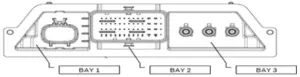
BAY1: HSAL Connector
BAY2: Main Connector
BAY3: RF Connector
Main Connector
Pin Number | Pin Description | CCU Pin Label | Remarks |
| A1 | Digital Output 1 | O_V_OUT1 | High Side Output |
| A2 | Digital-Output 3 | O_S_OUT3 | Low Side Output |
| A3 | Digital-Output 2 | O_S_OUT2 | Low Side Output |
| A4 | RS-485- | B_D_RS485_DM | Communication |
| B4 | RS-485+ | B_D_RS485_DP | Communication |
| C1 | AC signal monitoring Phase | I_A_ACDCP | AC signal monitoring Phase |
| C2 | AC signal monitoring Neutral | I_A_ACDCN | AC signal monitoring Neutral |
| C4 | RS-485 isolated ground | G_R_RS485ISO | Ground |
| D4 | Analog-Input4 | I_A_AN4 | Analog input |
| E3 | PWM input | I_T_PWM | PWM input |
| E4 | Analog-Input2 | I_A_AN2 | Analog input |
| F1 | Analog Ground | G_R_AN | Ground |
| F3 | Digital-Input5 | I_S_DIG5 | Digital input |
| F4 | KL15(Ignition) | I_S_T15 | Digital input |
| G1 | CAN1 high | B_D_CAN1H | Communication |
| G2 | RTC backup power (Coin cell) | V_V_RTC | Power |
| G4 | Analog-Input3 | I_A_AN3 | Analog input |
| H1 | CAN1 low | B_D_CAN1L | Communication |
| H2 | RTC backup ground (Coin cell) | G_G_RTC | Ground |
| H4 | Digital-Input2 | I_S_DIG2 | Digital input |
| J1 | Digital-Input4 | I_S_DIG4 | Digital input |
| J2 | Digital-Input1 | I_S_DIG1 | Digital input |
| J3 | CAN0 high | B_D_CAN0H | Communication |
| J4 | CAN1-Shield | G_G_CAN1SH | Shield |
| K1 | Digital-Input3 | I_S_DIG3 | Digital input |
| K3 | CAN0 low | B_D_CAN0L | Communication |
| K4 | CAN0-Shield | G_G_CAN0SH | Shield |
| L2 | Backup battery supply | V_V_BAK_BAT | Power |
| L4 | Backup battery Ground | G_G_BAK_BAT | Ground |
| M1 | Vehicle Battery Plus | V_V_BAT | Power |
| M4 | Vehicle Battery Ground | G_G_BAT | Ground |
RF Connector
| Pin Number | Signal Description |
| 1 | GNSS Antenna Port |
| 2 | LTE Main Antenna Port |
| 3 | LTE Diversity / WIFI Antenna Port |
HSAL Connector
Pin Number | Pin Description | CCU Pin Label | Remarks |
| 1 | Ethernet TX – | B_D_ETH_TXM | Signal |
| 2 | Ethernet TX + | B_D_ETH_TXP | Signal |
| 3 | Ethernet GND | G_G_ETHSH1 | Shield Ground |
| 5 | USB Supply | V_V_USB | Supply for USB |
| 6 | USB GND | G_G_USB | GND For USB |
| 7 | Ethernet RX + | B_D_ETH_RXP | Signal |
| 8 | Ethernet RX – | B_D_ETH_RXM | Signal |
| 9 | Ethernet GND | G_G_ETHSH2 | Shield Ground |
| 10 | Ethernet GND | G_G_ETHSH3 | Shield Ground |
| 11 | USB D+ | B_D_HSD_DP | USB Data Plus |
| 12 | USB D- | B_D_HSD_DM | USB Data minus |
Best Practice for Wiring Routing
- Due to the effects of gravity passing water through the wires, the CCU should be packaged higher than any wire end or splice in the harness.
- Measures should be taken to prevent water from collecting around the wiring harness. Plastic wire covering/protection should allow water to drain from harness.
- Wiring should be routed away from water drainage areas. Wires that are routed around sharp edges or that can be damaged from stone impingements should be protected.
- Water in the wiring harness can cause interference on various signal wires due to poor wiring insulation.
- Wires splices and ground eyelets must be located away from direct contact with high pressure cleaner.
- Any wire end terminating in a splash water area should be orientated so that the wire end is pointing down.
Grounding Scheme
The grounding scheme for Gen2A is as seen below: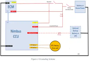
Robert Bosch Engineering and Business Solutions Private Limited
123. Industrial Layout,
Hosur Road,
Koramangala,
Bangalore – 560095,
INDIA
Email: [email protected]
Official Website: www.bosch-india-software.com


