JENNAIR JJW2424HM 24-Inch Smart Built-In Convection Oven Instruction Manual
INSTALLATION INSTRUCTIONS SIDE TRIM COVER KIT FOR PYRO, SPEED AND STEAM BUILT-IN OVENS, OR COFFEE MACHINE
Pyro Built-In Single Oven Side Trim Cover Kit W11312047 for 27″ (68.6 cm) and 30″ (76.2 cm) cabinets
For use with model : JJW2424HM
Pyro Built-In Single Oven Side Trim Cover Kit W11312048 for 27″ (68.6 cm) and 30″ (76.2 cm) cabinets
For use with model : JJW2424HL
Steam Built-In Single Oven, Speed Microwave Built-In Oven and Coffee Machine Side Trim Cover Kit W11290015 for 27″ (68.6 cm) and 30″ (76.2 cm) cabinets
For use with models : JJW6024HM, JMC6224HM, JJB6424HM
Steam Built-In Single Oven, Speed Microwave Built-In Oven and Coffee Machine Side Trim Cover Kit W11300447 for 27″ (68.6 cm) and 30″ (76.2 cm) cabinets
For use with models : JJW6024HL, JMC6224HL, JJB6424HL
BUILT-IN SINGLE OVEN, MICROWAVE OR COFFEE MACHINE SAFETY
Your safety and the safety of others are very important.
We have provided many important safety messages in this manual and on your appliance. Always read and obey all safety messages.

This is the safety alert symbol.
This symbol alerts you to potential hazards that can kill or hurt you and others.
All safety messages will follow the safety alert symbol and either the word “DANGER” or “WARNING.” These words mean:
![]()
You can be killed or seriously injured if you don’t immediately follow instructions.
![]()
You can be killed or seriously injured if you don’t follow instructions.
All safety messages will tell you what the potential hazard is, tell you how to reduce the chance of injury, and tell you what can happen if the instructions are not followed.
INSTALLATION REQUIREMENTS
Tools and Parts
Gather the required tools and parts before starting installation. Read and follow the instructions provided with any tools listed here.
Tools needed
- Phillips screwdriver
- Measuring tape
- Level
- Hex head or flat-blade screwdriver
Parts supplied

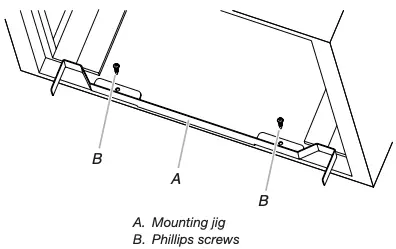
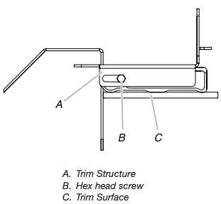
A. Mounting jig
B. Trim surface (2 per 27″ (68.6 cm) and 2 per 30″ (76.2 cm) cabinets)
C. Trim structure (2 per 27″ (68.6 cm) and 2 per 30″ (76.2 cm) cabinets)
D. 2 Self Drilling Screws
E. 8 Wood Screws
F. 2 Hex Head screws
Location Requirements
IMPORTANT: Observe all governing codes and ordinances.
- Follow the instructions below along with the instructions in the built-in oven, microwave or coffee machine Installation Instructions.
Product Dimensions
Side Trim Cover Kits

Cabinet Dimensions

*Distance between additional bottom cleats for ovens.
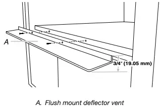
If the unit is being installed above a wooden cabinet bottom, be sure to install the metal trim piece at the front edge of the cabinet bottom.
Refer the below dimensions along with the dimensions in the built-in oven, microwave or coffee machine dimension guide.

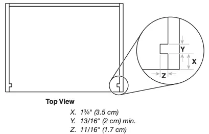
Side Cleats Dimensions
INSTALLATION INSTRUCTIONS
Install Side Trim Cover Kit for Built-In Oven, Steam, Microwave, or Coffee Machine
For Flush Installation
Follow the instructions below to install the Side Trim Cover Kit on a built-in oven steam, microwave, or coffee machine.
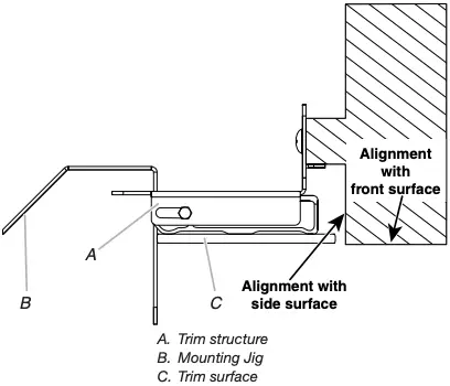
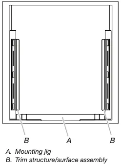
- Center the mounting jig horizontally in the cabinet opening, place it flush against the cabinet opening, and secure it with two Phillips screws as shown.

- Attach each trim surface to the trim structure with hex-head screws at the top and bottom. Do not tighten the screws completely.

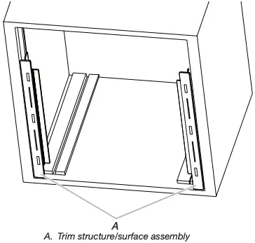
- Align each trim structure/surface assembly with the cabinet as shown and attach each with four Phillips screws.

- Adjust the trim structure/surface assemblies horizontally to touch the side surfaces of the mounting jig. Tighten the hex-head screws at the top of each assembly.

- Remove the mounting jig from the cabinet opening. Tighten the hex-head screws at the bottom of each trim structure/ surface assembly.

Install Electric Built-in Single Oven or Microwave
- Follow the oven Installation Instructions to complete installation.
NOTE: If the built-in oven was not installed into the cabinet, read the “Electrical Requirements” and “Electrical Connection” sections, along with all other sections of the Installation Instructions, before installing the oven.
Excessive Weight Hazard
Use two or more people to move and install oven.
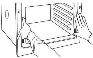
Failure to do so can result in back or other injury. - Using two or more people, push against the seal area of the front frame to push the oven into the cabinet until the back surface of the front frame touches the Trim structure.

- Securely fasten oven to the metal trim structure using the screws provided. Insert the self drilling screws through hole in the side trim cover. Do not over tighten screws.
- Reconnect power.
- If the display panel does not light, reference the “Assistance or Service” section of the Use and Care Guide, or contact the dealer from whom you purchased your oven.
Install Coffee System
Install the Mounting Brackets
- Make side wooden blocks with the dimensions as shown.

- Secure the side wooden blocks to the side walls of the cabinet and wooden bottom spacer so that the coffee system can be installed as per the Installation Instructions.

- After securing the ‘blocks’, the distance between them should be 22 1 /16″ (55.97 cm). If the distance between the mounting brackets is greater than 22″ + 1⁄16″ (55.9 + 0.07 cm), bracket spacers will need to be used. Four 1 mm bracket spacers are included. See Step 4.
- If bracket spacers are needed: Position the necessary spacer(s) behind the mounting brackets. Continue with Step 5.

- Determine where the mounting brackets will be installed and mark 6 holes through each mounting bracket onto the side cabinet.
IMPORTANT: The front of the mounting bracket must be 1/16″ (2 mm) from the front fascia thickness of the cabinet frame.
Align the front of the mounting brackets 13/16″ (2.1 cm) back from the front of the cabinet and mark 6 holes through each mounting bracket onto the blocks.
- Using a 1/16″ (2 mm) drill, drill the holes marked in Step 5.
- Secure the mounting brackets to the side cabinets with six 3/16″ x 5/8″ (4.5 x 16 mm) screws in each bracket.
- Remove the tape holding the brackets in place.
- Pull the runners forward until they are fully extended and in the locked position. Place level across the runners and check levelness. Then place the level along the length of each runner and check levelness from front to back. If the runners are not level, uninstall the mounting brackets and raise or lower the mounting brackets as necessary until they are level.

NOTE: If the runners are not level, uninstall the mounting brackets and raise the mounting brackets as necessary using the metal shims provided, until they are level.
- If the coffee system is being installed above a wooden cabinet bottom, use two 3/16″ x 5/8″ (4.5 x 16 mm) screws to install the metal trim piece at the front edge of the cabinet bottom.


Install the Coffee System
![]()
Excessive Weight Hazard
Use two or more people to move and install the built-in coffee system.
Failure to do so can result in back or other injury.
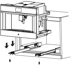
- Pull the runners forward until they are fully extended.
- Using 2 or more people, position the coffee system onto the runners, making sure that the 2 hooks on the back of the mounting brackets are inside the holes on the rear/back/ bottom of the coffee system. Pull runners all the way forward and in the locked position.

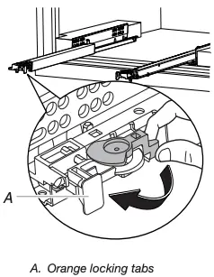
NOTE: There is a white ‘dial’ on the front of the runners that can be rotated for minor height adjustments. Lock coffee system into place using the ‘orange locking tabs’.
- Secure the coffee system to the runners with the two, 3/16″ x 3/8″ (4.2 x 9.5 mm) screws.
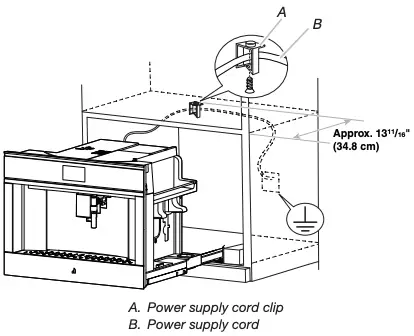
- Position the power supply cord clip on the top of the cabinet, approximately 13 11/16″ (34.8 cm) from the front of the cabinet and centered from left to right. With a pencil, mark the hole through the clip on the top of the cabinet.
- Using a 1/16″ (2 mm) drill, drill the hole marked in Step 4.
- Using one 3/16″ x 5/8″ (4.5 x 16 mm) screw, attach the power supply cord clip to the top of the cabinet.

- Secure the power supply cord with the power supply cord clip. Make sure there is enough slack in the power supply cord to allow the coffee system to be pulled completely from the cabinet in order to fill the coffee bean container.

Electrical Shock Hazard
Plug into a grounded 3 prong outlet.
Do not remove ground prong.
Do not use an adapter.
Do not use an extension cord.
Failure to follow these instructions can result in death, fire, or electrical shock. - Plug the coffee system into a grounded 3-prong outlet.
- Push the coffee system back into the housing.
- Proceed to “Complete Installation” section.

Complete Installation
- Check that all parts are now installed. If there is an extra part, go back through the steps to see which step was skipped.
- Check that you have all of your tools.
- Dispose of/recycle all packaging materials.
If you need Assistance or Service:
Please reference the “Assistance or Service” section of the Use and Care Guide or contact the dealer from whom you purchased your trim kit.
©2019 All rights reserved. Used under license in Canada.
Documents / Resources
 | JENNAIR JJW2424HM 24-Inch Smart Built-In Convection Oven [pdf] Instruction Manual JJW2424HM, 24-Inch Smart Built-In Convection Oven |


