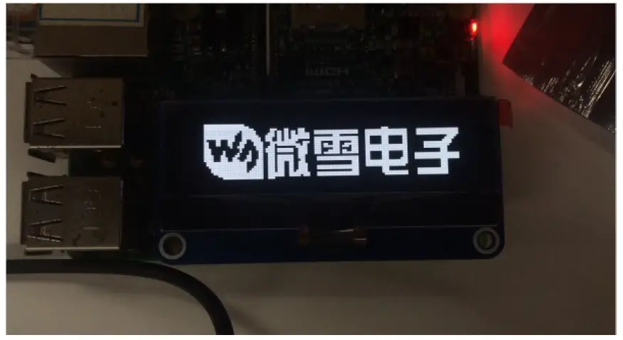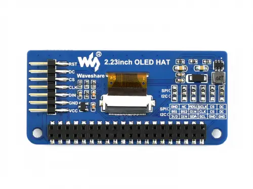
WIS 2.23inch OLED HAT
PINS
| PIN | Description |
| VCC | 3.3V/5V |
| GND | GND |
| DIN | MOSI of SPI interface / SDA of I2C interface |
| CLK | SCLK of SPI interface / SCL of I2C interface |
| CS | Chip select of SPI interface (Low active) / GND when set to I2C itnerface |
| DC | Command / Data selection (SPI) / GND (I2C) |
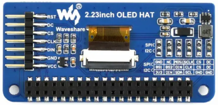 The interface of 2.23inch OLED HAT is default SPI interface, that is 0R resistors are soldered to SPI sides. If you want to use I2C interface, you need to solder the 0R resistors to I2C side,
Working principle
SSD1305 is a controller for 132*64 resolution OLED, however, this 2.23inch OLED HAT has only 128*32 resolution, therefore only part of SSD1305’s buffer are used.
I2C
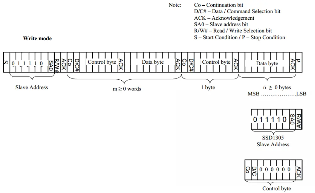
At the begging, the Master device sends a byte (7 bits address and 1 bit R/W)to slaver device and wait for a response.
After getting response, the Master device sends a control byte, this byte tells slave device the data followed later is command or data.
Then Master device will send data or command to slaver device.
For more details please refer to Page22 Figure 8-6 of Datasheet
SPI
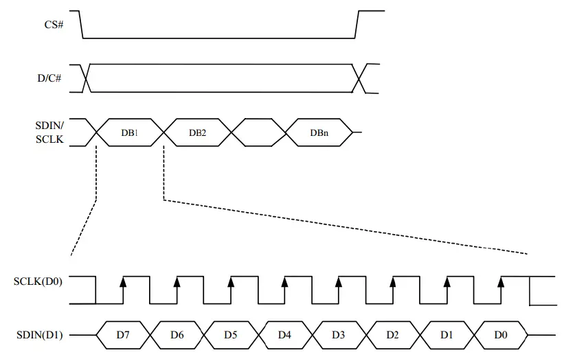
For details of the SPI communicating, you can refer to Datasheet Page21 Figure8-5.
Exampels
We provide examples for this module based on three popular hardware platform (STM32, Arduino and RaspberryPi). The libraries include supports Drawing points, lines, figures and displaying strings.
You can download the codes from [[#Demo codes] and unzip it to get examples.
STM32 examples
STM32 example is based on Waveshare (XNULCEO-F103RB)
| I2C Interface | |
| 2.23inch OLED HAT | STM32 Board |
| VCC | 3.3V |
| GND | GND |
| DIN | PB15 |
| CLK | PB13 |
| SPI interface | |
| 2.23inch OLED HAT | STM32 Board |
| VCC | 3.3V |
| GND | GND |
| DIN | PB15 |
| CLK | PB13 |
| CS | PB12 |
| DC | PC6 |
Open project, compile and download to XNUCLEO-F103RB board
Raspberry Pi example
Hardware connection
| I2C interface | |
| 2.23inch OLED HAT | Raspberry Pi (BCM) |
| VCC | 3.3V |
| GND | GND |
| DIN | SDA |
| CLK | SCL |
| SPI interface | |
| 2.23inch OLED HAT | Raspberry Pi(BCM) |
| VCC | 3.3V |
| GND | GND |
| DIN | MOSI |
| CLK | SCLK |
| CS | CE0 |
| DC | 24 |
| RST | 25 |
Software setting
Open terminal of Raspbain and enable I2C/SPI interface
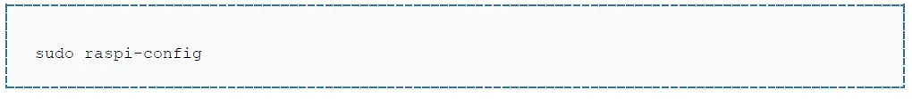
Choose Interfacing Options -> I2C -> Yes; or
Choose Interfacing Options -> SPI ->Yes;
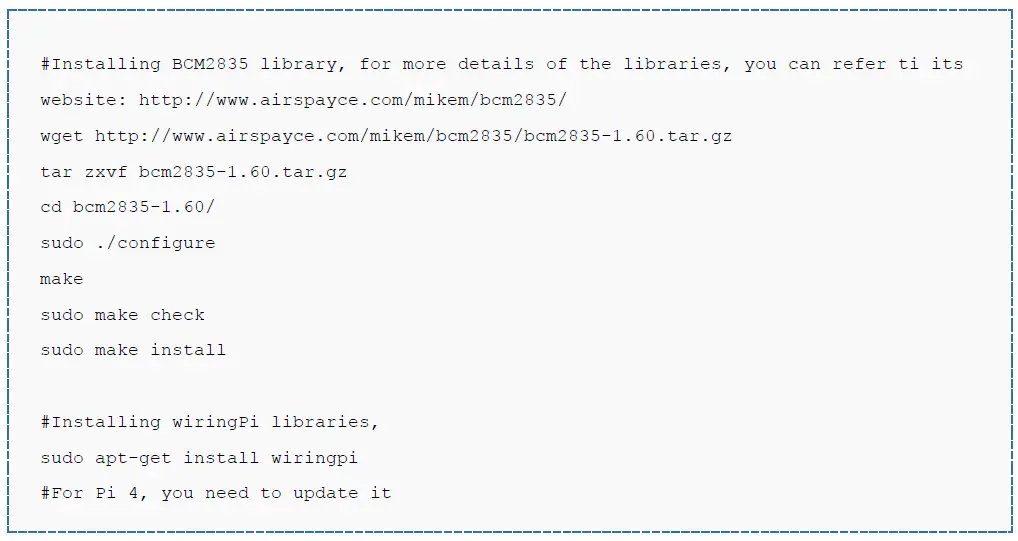
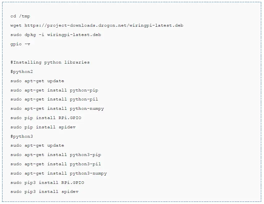
Libraries Installation
Open terminal of Raspbain and install libraries (BCM2835, wiringPi, Python) as below
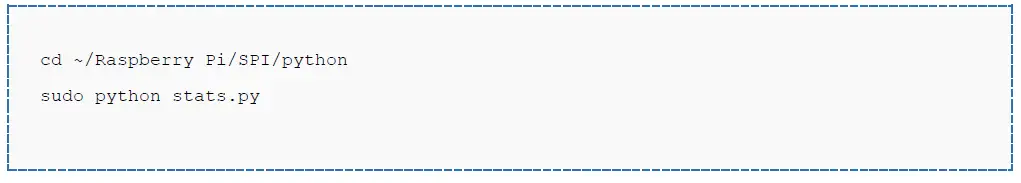
Runing example (Take SPI codes as example)
Copy Raspberry Pi codes which is downloaded before to Raspberry Pi, put it to /home/pi of Raspbian
Enter the corresponding directory of codes and execute commands to run:
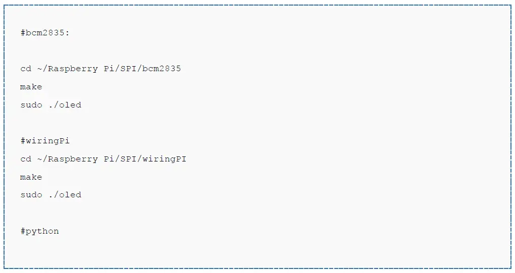
Note: If wiringPi and Python example work abnormally after bcm2835 example, please reboot and test again.
Arduino example
This examples are based on Waveshare UNO PLUS which is compatible with official Arduino UNO R3
• Connect OLED to UNO Plus according to figure below:
| I2C interface | |
| PIN | UNO PLUS |
| VCC | 3.3V |
| GND | GND |
| DIN | SDA/D14 |
| CLK | SCL/D15 |
| SPI interface | |
| PIN | UNO PLUS |
| VCC | 3.3V |
| GND | GND |
| DIN | D11(MOSI) |
| CLK | D13(SCK) |
| CS | D10 |
| DC | D8 |
| RST | D9 |
How to create image data
• Open Image2Lcd software
• Open an BMP file
• Set Data type: *c
Scanning type: Horizontal
Grey Scale: Monochrome
Max height and width: 128 32
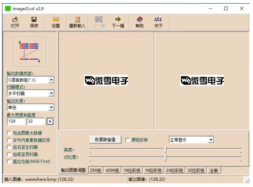
The expected result: