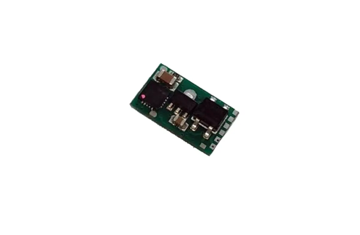
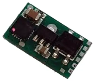
mXion DRIVE-XS Main Board
Introduction
Dear customer, we strongly recommend that you read these manuals and the warning notes thouroughly before installing and operating your device. The device is not a toy (15+).
NOTE: Make sure that the outputs are set to appropriate value before hooking up any other device. We can’t be responsible For any damage if this is disregarded.
General information
We recommend studying this manual thoroughly before installing and operating your new device.
Place the decoder in a protected location. The unit must not be exposed to moisture.
NOTE: Some funktions are only available with the latest firmware. Please make sure that your device is programmed with the latest firmware.
Summary of Funktions
- DCC operation
- For all scales available Z to G, perfekt for ZH0
- Compatible NMRA-DCC module
- 0.5 Amps engine output
- Temperature and over current protection Very small module
- Differend forward and backward speeds 2 reinforced function output
- 1 dereinforced LED function output
- Lot of special and time functions available 23 light effects on all outputs
- Function outputs dimmable
- Reset function for all CV values
- Easy function mapping
- 68 function keys programmable, 10239 loco
- 14, 28, 128 speed steps (automaticly)
- Multiple programming options
- (Bitwise, CV, POM accessoire decoder, register)
- Needs programming load
- Free function mapping (F0 – F68) for all
- Voltage puffer connection for same run
- Simple, easy understand function mapping
- Lot of functions configurable
Scope of supply
Manual
mXion DRIVE-XS
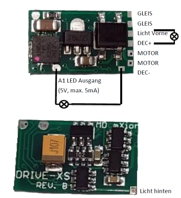
Hook-Up
Install your device in compliance with the connecting diagrams in this manual. The device is protected against shorts and excessive loads. However, in case of a connection error e.g. a short this safety feature can’t work and the device will be destroyed subsequently.
Make sure that there is no short circuit caused by the mounting screws or metal.
NOTE: Please note the CV basic settings in the delivery state.
Connectors
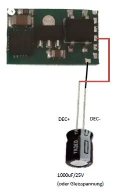
Connection for Buffer
The voltage of the buffer must be 2 volts higher than on the track.
Product description
The mXion DRIVE-XS is a very strong 0.5 train decoder. he can be digital
and analog works and offers with its 3 output. Its perfectly fitting for scale Z to H0.
The standard scope of course includes a maneuvering as well as turn-off delay times. In analog mode, all outputs are full functionality also usable.
Ideally also as function decoder or for motor uses with additonal function outputs.
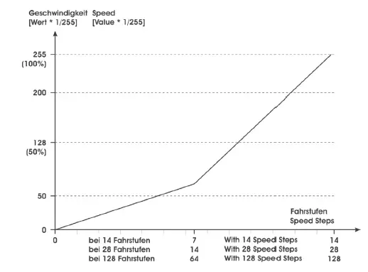
Speedsteps
The speed steps (speed increments between standstill and maximum speed) may be set to 14, 28 and 128. CV 29 Bit 1 must be set to 0 for 14 and to 1 for
28/128 speed steps. The difference between 28 and 128 are detected automatically.
LGB MTS I and II require 14 speed steps. The standard setting is 28/128 speed steps.
Speed curves
The speed characteristic of the locomotive is defined by the speed curve. You may choose between a linear speed curve or a freely programmable speed curve. The linear speed curve is defined by 3 CVs.
The standard speed curve is linear because it is easier to be set (CV 29). The start voltage (CV 2) defines the driving voltage of speed step 1. The smaller the the slower the locomotive starts driving. If the PI-Load control is „off“ and the locomotive does not move with speed step 1, the start voltage should be increased. The maximum speed
(CV 5) my be reduced by inserting smaller values. Decreasing CV 5 alters all speeds in a linear way. The mid-speed (CV 6) influences the linearity of the speed curve. In the case CV 6 is half of the value of CV 5 (max. seep), all speed steps are distributed equally.
In case CV 6 is smaller than half the value of CV 5, the lower speed steps will be stretched. The locomotive will drive slower at mid-speed; the slow speed range will be extended (ideal for shunting).
As an alternative you may program the speed curve individually in 28 steps
(CV 67 – 94). This speed curve is activated by CV 29 bit 4. In this case the CVs 2,5,6 are deactivated!
Programming lock
To prevent accidental programming to prevent CV 15/16 one programming lock. Only if CV 15 = CV 16 is a programming possible. Changing CV 16 changes automatically also CV 15.
With CV 7 = 16 can the programming lock reset.
STANDARD VALUE CV 15/16 = 205
Programming options
This decoder supports the following programming types: bitwise, POM and CV read & write and register-mode.
There will be no extra load for programming.
In POM (programming on maintrack) the programming lock is also supported. The decoder can also be on the main track programmed without the other decoder to be influenced. Thus, when programming the decoder can not be removed.
NOTE: To use POM without others decoder must affect your digital center POM to specific decoder adresses.
Programming binary values
Some CV’s (e.g. 29) consist of so-called binary values. The means that several settings in a value. Each function has a bit position and a value. For programming such a CV must have all the significances can be added. A disabled function has always the value 0.
EXAMPLE: You want 28 drive steps and long loco address. To do this, you must set the value in CV 292 + 32 = 34 programmed.
Acceleration and Deceleration
The acceleration and deceleration characteristic may be defined with CV 3 (acceleration) and CV 4 (deceleration).
The CV setting represents the time the decoder takes to reach a newly selected speed. The values in CV 3 and CV 4 are time units. One unit equals 0.5 seconds. To get your intended acceleration/deceleration time by 2 and programm this in CV 3 and CV 4.
Programming loco adress
Locomotives up to 127 are programmed directly to CV 1. For this, you need CV 29 Bit 5 „off“ (will set automaticly).
If larger addresses are used, CV 29 – Bit 5 must be „on“ (automaticly if change CV 17/18). The address is now in CV 17 and CV 18 stored. The address is then like follows (e.g. loco address 3000):
3000 / 256 = 11,72; CV 17 is 192 + 11 = 203. 3000 – (11 x 256) = 189; CV 18 is then 189.
Reset functions
The decoder can be reset via CV 7. Various areas can be used for this purpose.
Write with the following values:
- 11 (basic functions)
- 16 (programming lock CV 15/16)
- 22 (light functions CV 50 – CV 59)
- 33 (function outputs 1-2)
- 44 (engine control)
- 66 (drive courve CV 67 – CV 94)
Function output features
| Funktion | A1 | A2 | A3 | Timevalue |
| On/Off | X | X | X | |
| Deactivated | X | X | X | |
| Permanent-On | X | X | X | |
| Forwards only | X | X | X | |
| Backwards only | X | X | X | |
| Standing only | X | X | X | |
| Driving only | X | X | X | |
| Timer sym. flash | X | X | X | X |
| Timer asym. short | X | X | X | X |
| Timer asym. long | X | X | X | X |
| Monoflop | X | X | X | X |
| Switch on delay | X | X | X | X |
| Firebox | X | X | X | |
| TV flickering | X | X | X | |
| Photographer flash | X | X | X | X |
| Welding light | X | X | X | |
| Petroleum flickering | X | X | X | |
| Flourescent tube | X | X | X | |
| Flourescent tube defect | X | X | X | |
| Sodium lamp | X | X | X | |
| US strobelight | X | X | X | |
| US double strobelight | X | X | X | |
| US marslight | X | X | X | X |
| Fade in/out | X | X | X | |
| Invers | X | X | X | |
| Autom. switch back | X | |||
| Dimmable | X | X | X | |
| Servo | ||||
| Buffer control | X | X | X | |
| Clock simulation | X | |||
| Pulsed smoke unit | X |
CV-Tabelle
S = Standard, A = Analogbetrieb nutzbar
| CV | Description | S | A | Range | Note |
| 1 | Loco address | 3 | L | 1 – 127 | if CV 29 Bit 5 = 0 (automatically reset) |
| 2 | Starting voltage | 58 | 0 – 255 | CV 2 x (1/255 track voltage) | |
| 3 | Acceleration time | 20 | 0 – 255 | CV 3 x 2ms x (1/255 track voltage) | |
| 4 | Braking time | 20 | 0 – 255 | CV 4 x 2ms x (1/255 track voltage) | |
| 5 | Top speed | 200 | 0 – 255 | CV 5 x (1/255 track voltage) | |
| 6 | Mid speed | 120 | 0 – 255 | CV 6 x (1/255 track voltage) | |
| 7 | Software version | – | – | read only (10 = 1.0) | |
| 7 | Decoder reset functions | ||||
|
6 ranges available | 11 16 22 33 44 | basic settings (CV 1,11-13,17-19,29-119) programming lock (CV 15/16) light outputs (CV50-59) function outputs (CV 1×0-1×4) engine functions (CV2-6,9,10,54-25,60-66) | |||
| 8 | Manufacturer ID | 160 | – | read only | |
| 7+8 | Register programming mode | ||||
| Reg8 = CV-Address Reg7 = CV-Value | CV 7/8 don’t changes his real value CV 8 write first with cv-number, then CV 7 write with value or read (e.g.: CV 49 should have 3) è CV 8 = 49, CV 7 = 3 writing | ||||
| 15 | Programming lock (key) | 205 | 0 – 255 | to lock only change this value | |
| 16 | Programming lock (lock) | 205 | 0 – 255 | changes in CV 16 will change CV 15 | |
| 17 | Long loco address (high) | 128 | L | 128 – 10239 | activ only if CV 29 Bit 5 = 1 (automatically set if change CV 17/18) |
| 18 | Long loco address (low) | ||||
| CV | Description | S | A | Range | Note | ||
| 29 | NMRA configuration | 6 | bitwise programming | ||||
| Bit | Value | OFF (Value 0) | ON | ||||
| 0 | 1 | standard driving direction | reverse driving direction | ||||
| 1 | 2 | 14 speed steps | 28/128 speed steps | ||||
| 4 | 16 | internal driving courve | programm. drive courve | ||||
| 5 | 32 | short loco address (CV 1) | long loco address (CV 17/18) | ||||
| 63 | Time for CV96 hand brake | 0 | 0 – 255 | 0 = always normal op 1 – 255 wait time in seconds | |||
| 65 | Kickstart | 65 | minimal engine voltage | ||||
| 66 | Forward-Trimm | 255 | 1 – 255 | reduce the maximum speed forward (CV66 * CV5 / 255) | |||
| 67- 94 | Freely programmable speed curve | 1 – 255 | see attachment 6 | ||||
| 95 | Forward-Trimm | 255 | 1 – 255 | reduce the maximum speed backward (CV95 * CV5 / 255) | |||
| 120 | A1 command allocation | 1 | see attachment 1 | ||||
| 121 | A1 dimming value | 100 | see attachment 2 | ||||
| 122 | A1 condition | 0 | see attachment 3 | ||||
| 123 | A1 special function | 0 | see attachment 4 | ||||
| 124 | A1 time for special function | 5 | 1 – 255 | time base (0,1s / value) | |||
| 125 | A2 command allocation | 2 | see attachment 1 | ||||
| 126 | A2 dimming value | 100 | see attachment 2 | ||||
| 127 | A2 condition | 0 | see attachment 3 | ||||
| 128 | A2 special function | 0 | see attachment 4 | ||||
| 129 | A2 time for special function | 5 | 1 – 255 | time base (0,1s / value) | |||
| 130 | A3 command allocation | 3 | see attachment 1 | ||||
| 131 | A3 dimming value | 100 | see attachment 2 | ||||
| 132 | A3 condition | 0 | see attachment 3 | ||||
| 133 | A3 special function | 0 | see attachment 4 | ||||
| 134 | A3 time for special function | 5 | 1 – 255 | time base (0,1s / value) | |||
| ATTACHMENT 1 – Command allocation | ||
| Value | Application | Note |
| 0 – 68 | 0 = Switch with light key 1 – 68 = Switch with F-key | |
| +64 | permanent off | |
| +128 | permanent on | |
| ATTACHMENT 2 – Dimming value | ||
| Value | Application | Note |
| 0 – 100 | dimming value | in % (1 % is around 0,2 V) |
| +128 | fade in/out | |
| ATTACHMENT 3 – Condition | ||
| Value | Application | Note |
| 0 | permanent (normal function) | |
| 1 | forward only | |
| 2 | backward only | |
| 3 | standing only | |
| 4 | standing „forward“ only | |
| 5 | standing „backward“ only | |
| 6 | driving only | |
| 7 | driving „forward“ only | |
| 8 | driving „backward“ only | |
| ATTACHMENT 4 – Special function | ||
| Value | Application | Note |
| 0 | no special function (normal output) | |
| 1 | flash symetric | time base (0,1s / value) |
| 2 | flash asymetric short ON (1:4) | time base (0,1s / Value) is for the long value |
| 3 | flash a symetric long ON (4:1) | |
| 4 | Photographer flash | time base (0,25s / value) |
| 5 | monoflop (automatic switch off) | time base (0,1s / value) |
| 6 | switch on delayed | time base (0,1s / value) |
| 7 | firebox | |
| 8 | TV flickering | |
| 9 | petroleum flickering | |
| 10 | flourescent tube | |
| 11 | defective flourescent tube | |
| 12 | alternating flash to paired output | in combination with second output (e.g. A1 & A2, A3 & A4) |
| 13 | US strobelight | |
| 14 | US double strobelight | |
| 15 | US marslight | time base (0,1s / value) |
| 16 | US ditch light | in combination with second output (e.g. A1 & A2, A3 & A4), 1st output normal light, 2nd ditch light function |
| 17 | sodium lamp | |
| 18 | welding light | use with blue led |
| 20 | Buffer control “BC” | |
| 21 | Clock simulation | CV116 corrects time |
| 24 | Kupplungswalzer | |
| +64 | Far away light adding | Far away light over CV 97 |
| +128 | invers | add value to function |
| ATTACHMENT 6 – Basic values of freely progr. driving curve (CV67 – 94) | |||||||||
| CV | 67 | 68 | 69 | 70 | 71 | 72 | 73 | 74 | 75 |
| WERT | 6 | 8 | 10 | 13 | 16 | 19 | 22 | 26 | 31 |
| CV | 76 | 77 | 78 | 79 | 80 | 81 | 82 | 83 | 84 |
| WERT | 36 | 42 | 48 | 54 | 60 | 68 | 76 | 84 | 92 |
| CV | 85 | 86 | 87 | 88 | 89 | 90 | 91 | 92 | 93 |
| WERT | 102 | 112 | 124 | 136 | 152 | 168 | 188 | 208 | 228 |
| CV | 94 | – | – | – | – | – | – | – | – |
| WERT | 232 | – | – | – | – | – | – | – | – |
Technical data
- Power supply:
0-27V DC/DCC
0-22V AC - Current:
15mA (with out functions) - Maximum function current:
A1 each 0.1 Amps. - Motor output
0.5 Amps - Maximum current:
1 Amps. - Temperature range:
-20 up to 60°C - Dimensions L*B*H (cm):
1*1.6*0.5
NOTE: In case you intend to utilize this device below freezing temperatures, make sure it was stored in a heated environment before operation to prevent the generation of condensed water. During operation is sufficient to prevent condensed water.
Warranty, Service, Support
micron-dynamics warrants this product against defects in materials and workmanship for one year from the original date of purchase. Other countries might have different legal warranty situations. Normal wear and tear,consumer modifications as well as improper use or installation are not covered. Peripheral component damage is not covered by this warranty. Valid warrants claims will be serviced without charge within the warranty period. For warranty service please return the product to the manufacturer. Return shipping charges are not covered by micron-dynamics. Please include your proof of purchase with the returned good. Please check our website for up to date brochures, product information, documentation and software updates. Software updates you can do with our updater or you can send us the product, we update for you free.
Errors and changes excepted.
Hotline
For technical support and schematics for application examples contact: micron-dynamics
[email protected]
[email protected]
www.micron-dynamics.de
https://www.youtube.com/@micron-dynamics


 Display User Guide")


