
![]()
Wireless Transmission System for sensors
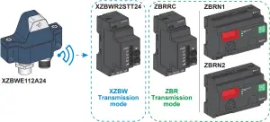
| Compatible receiver | Max. number of transmitters | Output | |
| ZBRRC | ZBR Transmission mode | 32 XZBWE112A24 (Version ≥ 1.2) | 4 x PNP |
| XZBWR2STT24 | XZBW Transmission mode | 2 XZBWE112A24 (All versions) | 2 x PNP (Q1 & Q2) |
| ZBRN1 | ZBR Transmission mode | 60 XZBWE112A24 (Version ≥ 1.2) | Ethernet modbus TCP |
| ZBRN2 | Modbus serial line | ||
![]()
![]() DANGER
DANGER
HAZARD OF ELECTRIC SHOCK, EXPLOSION OR ARC FLASH
- Disconnect all power before servicing equipment.
- Use only the specified voltage when operating this equipment and any associated products.
Failure to follow these instructions will result in death or serious injury.
![]() WARNING
WARNING
UNINTENDED EQUIPMENT OPERATION
- Do not use this equipment in safety critical machine functions.
- Use appropriate safety interlocks where personnel and/or equipment hazards exist.
- Do not disassemble, repair, or modify this equipment.
- Install and operate this equipment in an appropriately rated enclosure for its intended environment.
- Install properly rated fuses as indicated on page 3 of this document.
- Check that the control is not activated if the product falls during transit.
Failure to follow these instructions can result in death, serious injury, or equipment damage.
Electrical equipment should be installed, operated, serviced, and maintained only by qualified personnel.
No responsibility is assumed by Schneider Electric for any consequences arising out of the use of this material.
© 2021 Schneider Electric. “All Rights Reserved.”
(A) Characteristics
| XZBWE112A24 | |
| Free field radio Range | 100 m |
| Typical radio range in industrial environment | 25 m |
| Operating temperature | -25…+55 °C / -13…131 °F |
| Storage temperature | -40…+70 °C / -40…158 °F |
| Power supply (transmitter alone) | 24 Vdc -15% / +20% – 15 mA |
| Output power supply for sensor | 24 V -15% / +20% – 100 mA max. (no overload protection) |
| Startup time | < 0,4 s |
| Response time | 30 ms |
| Input frequency | < 0,5 Hz |
| Input time | ON > 100 ms – OFF > 100 ms |
| Input state 0 | < 30% Valim ( 7,2 V … 24 V) – < 1,5 mA |
| Input state 1 | 85% Valim (20,4 V … 24 V) – = 1,6 mA |
| IP Protection | IP65, IP67 |
| Enclosure type 4 (indoor use and vertical mounting only) | |
| Display | Orange / Green LED |
| Receiver | XZBWR2STT24 “Only one receiver per transmitter XZBWE112A24” |
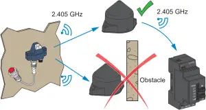
| ZigBee Green Power 2.405 GHz (channel 11 IEEE 802.15.4) compliant | |
| XZBWR2STT24 | |
| Operating temperature | -20…+55 °C / -4…131 °F |
| Storage temperature | -40…+70 °C / -40…158 °F |
| Power supply (receiver alone) | 24 Vdc – 100 mA max. |
| Outputs | 2 + 2 PNP – 200 mA (each output) |
| IP Protection | IP20 enclosure type 1 |
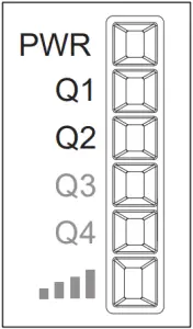
| Display | 1 LED for each output – 1 LED for power supply – 1 LED for signal strength |
| Startup time | < 0,4 s |
| Setup (pairing process) | 2 push buttons |
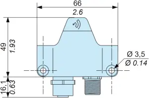
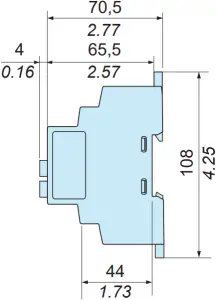
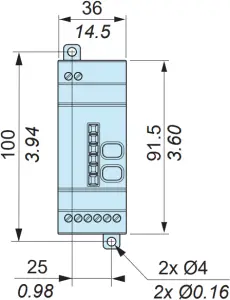
(B) Mounting instructions
Dimensions
mm/in. 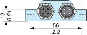
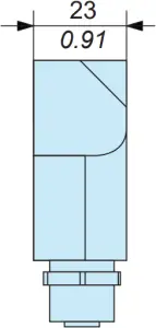
mm/in.
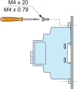
Mounting tips
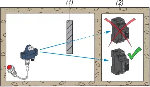
(1) Metal structure
(2) Wall
Signal attenuation according to the material
| Glass window | 10…20% (3) |
| Plaster wall | 30…45% (3) |
| Brick wall | 60% (3) |
| Concrete wall | 70…80% (3) |
| Metal structure | 50…100% (3) |
(3): Values for indication purposes only. Actual values depend on the thickness and nature of the material.
Unobstructed
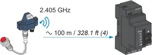
(4):Typical values that may be modified by the application environment.
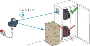
Metal cabinet
Mounting Tips for Antenna
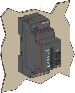
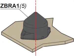
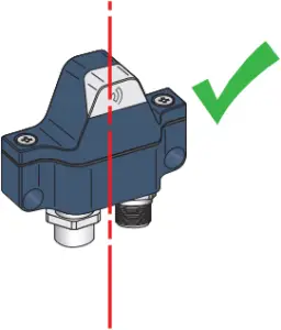
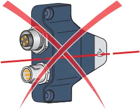
Optimized installation:
The XZBWE, the antenna and the receiver are installed following their vertical axis.
(5): ZBRA1 is incompatible with XZBWR2STT24.
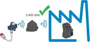
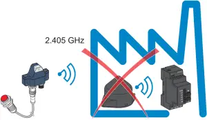
The relay antenna is used to bypass an obstacle and / or increase the range.
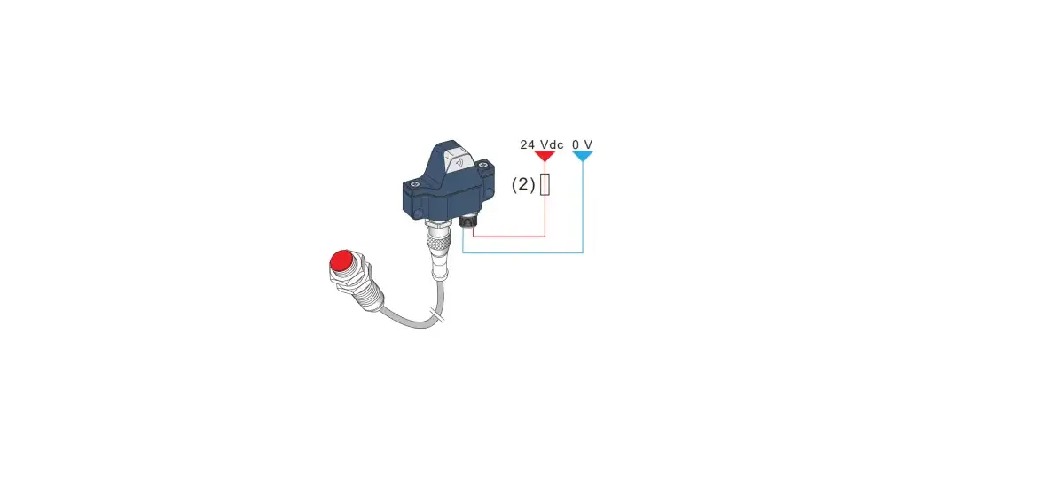
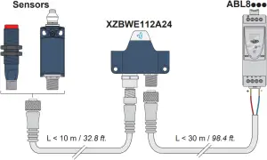
(C) Wiring diagrams
XZBWR2STT24 / ZBRRC XZBWE112A24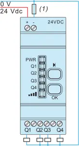
(1): 1 A fuse from supplier Bussmann® reference GMA-1A, 250 V fast-blow.
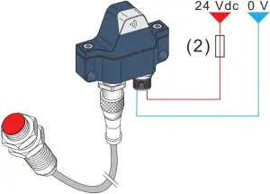
(2): 400 mA fast blow fuse – Telemecanique ref. XUZE04
Mm/in.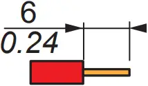 | 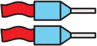 |  | ||
| mm² | 0,14…0,75 | 0,14…2,5 | 0,14…4 | 0,14…1,5 |
| AWG | 26…18 | 26…14 | 26…12 | 26…16 |
Ø 3,5 mm / 0.14 in. | 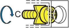 | Nm | 0,6 |
| lb-in | 5.3 |
| Socket Sensor Input | ||
| Pin. n° | Signal | |
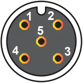 | 1 | +24 Vdc Output to sensor |
| 2 | not used | |
| 3 | 0 Vdc | |
| 4 | NO NPN or PNP or contact input from sensor | |
| 5 | not used | |
| Socket Power Supply (male) | ||
| Pin. n° | Signal | |
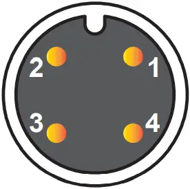 | 1 | +24 Vdc |
| 2 | not used | |
| 3 | 0 Vdc | |
| 4 | not used | |
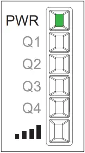
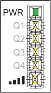
(D) LEDs Status
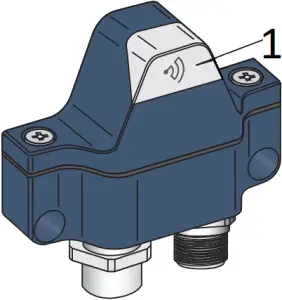
1
| LED | MODE |
| – | Power OFF |
| Input OFF | |
| Input ON | |
| Communication Error with receiver |
GN: Green
OG: Orange![]() Flashing
Flashing
(E) XZBWE: Transmission mode setting
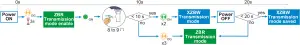
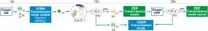
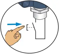 For the XZBWE setting, use a position switch or a push button
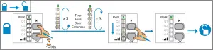
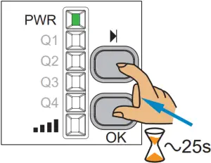
(F) Pairing or Unpairing
XZBWR2STT24
For ZBR products setting, you can refer to the User Guides: https://www.se.com/ww/en/download/document/EIO0000000812 https://www.se.com/ww/en/download/document/EIO0000001177
ZBRRC
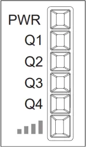
| LEDs Status | |
| Green ON | |
| Yellow ON | |
| Flashing | |
| Sequential | |
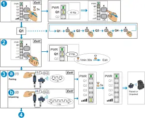
(1): All Outputs are inactive for 4 seconds after end of pairing procedure
(2): This function is impossible with the reference XZBWR2STT24
(4) Make a test by actuating the limit switch
Exit
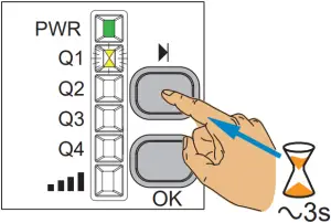

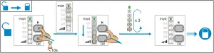
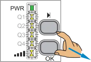
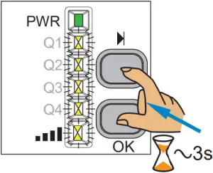
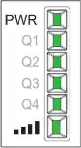
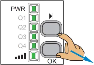
Electronic Lock/Unlock
This procedure shows how to electronically lock/unlock the receiver.
![]() : Locked
: Locked
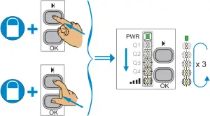
 : Unlocked
Total Reset: After a Total Reset the receiver is on factory setting.


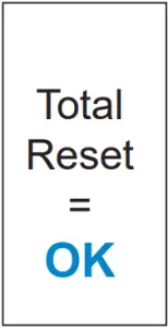
NOTE:
Before disassembly for storage, perform a full reset of the receiver memory.
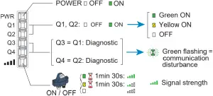
(E) Servicing and Diagnostic
E1 Diagnostic in RUN mode:
XZBWR2STT24
E2 Output operation
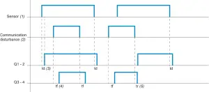
(1): Sensor
(2): Communication disturbance
(3): td = Delay: < 30 ms
(4): tf = Time-out in fault condition: < 1 mn
(5): tr = Recovery delay: < 1 mn
![]()
![]()
Simplified EU Declaration of Conformity
We, SCHNEIDER ELECTRIC INDUSTRIES SAS declare, under our sole responsibility, that the radio equipments:
Trademark : Telemecanique
Models : XZBW…
comply with Essential Requirements of following European Directives :
Radio Equipment Directive :
2014/53/EU
Regulations relative to the exposure to electromagnetic fields :
1999/519/EC
2013/35/EU
The full text of the EU Declaration of Conformity is available at the following internet address:
http://qr.tesensors.com/….
WARNING TO USERS IN THE UNITED STATES AND CANADA
WARNING TO USERS IN THE UNITED STATES
Federal Communication Commission Interference Statement
This equipment complies with FCC’s radiation exposure limits set forth for an uncontrolled environment under the following conditions:
1- This equipment should be installed and operated such that a minimum separation distance of 20 cm is maintained between the radiator (antenna) and user’s/nearby person’s body at all times.
2- This transmitter must not be co-located or operating in conjunction with any other antenna or transmitter.
This equipment has been tested and found to comply with the limits for a Class B digital device, pursuant to Part 15 of the FCC Rules. These limits are designed to provide reasonable protection against harmful interference in a residential installation. This equipment generates, uses and can radiate radio frequency energy and, if not installed and used in accordance with the instructions, may cause harmful interference to radio communications. However, there is no guarantee that interference will not occur in a particular installation.
If this equipment does cause harmful interference to radio or television reception, which can be determined by turning the equipment off and on, the user is encouraged to try to correct the interference by one of the following measures:
- Reorient or relocate the receiving antenna.
- Increase the separation between the equipment and receiver.
- Connect the equipment into an outlet on a circuit different from that to which the receiver is connected.
- Consult the dealer or an experienced radio/TV technician for help.
This device complies with Part 15 of the FCC Rules. Operation is subject to the following two conditions:
- This device may not cause harmful interference.
- This device must accept any interference received, including interference that may cause undesired operation.
NO UNAUTHORIZED MODIFICATIONS
CAUTION: This equipment may not be modified, altered, or changed in any way without signed written permission from SCHNEIDER ELECTRIC. Any changes or modifications to this equipment not expressly approved by SCHNEIDER ELECTRIC may cause harmful interference, will void the FCC authorization to operate this equipment and will void the SCHNEIDER ELECTRIC warranty.
WARNING TO USERS IN THE CANADA / ATTENTION POUR LES UTILISATEURS AU CANADA
This device contains license-exempt transmitter(s)/receiver(s) that comply with Innovation, Science and Economic Development Canada’s license-exempt RSS(s). Operation is subject to the following two conditions:
- this device may not cause interference, and
- this device must accept any interference received, including interference that may cause undesired operation of the device.
This equipment complies with RSS102’s radiation exposure limits set forth for an uncontrolled environment under the following conditions:
- This equipment should be installed and operated such that a minimum separation distance of 20 cm is maintained between the radiator (antenna) and user’s/nearby person’s body at all times.
- This transmitter must not be co-located or operating in conjunction with any other antenna or transmitter.
| XZBWE112A24 | XZBWR2STT24 | |
| FCC ID | Y7HXZBWE | Y7HXZBWR |
| IC | 7002C-XZBWE | 7002C-XZBWR |
| PMN | XZBWE112A24 | XZBWR2STT24 |
![]() NHA50158_02
NHA50158_02
10 – 2021


