![]() ULA1 UWB Development Module
ULA1 UWB Development Module
User Manual
ULA1 UWB Development Module
Introduction
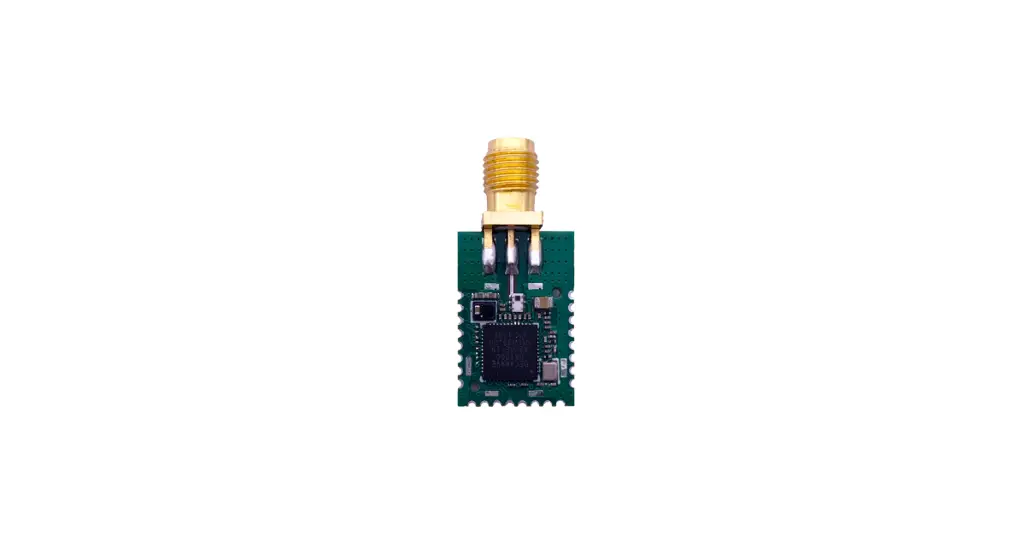
ULA1 is a UWB Development module which takes Arduino as the development environment and DWM1000 module of Decawave as the core UWB module. ULA1 can be used for precise ranging, indoor positioning and other high-speed data communication applications. A tyFigureal high-precision positioning system can be achieved by 4 anchors and 1 tag (ULA1 module can be used as an anchor or tag).
The system design is open source. We provide users with embedded source code, hardware schematic, PC software source code, video tutorials and other materials, to help users quickly learning how does the UWB positioning work and getting to work with it.
ULA1 module can be used as an anchor or tag.
HR-RTLS1 is a complete positioning system whicn consists of the combination of 5 or more ULA1 modules.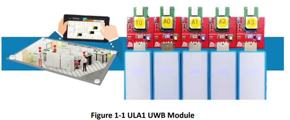
Table 1-1 ULA1 Module Parameters
| Category | Parameter |
| Module Model | ULA1 |
| Power | DC5V(USB) |
| Maximum Detection Range | 50m (open area) |
| MCU | ESP32 |
| Development Environment | Arduino |
| Module Size | 40*25mm |
| Ranging Accuracy | 10CM |
| Working Temperature | -20-80℃ |
Parameter configuration
| S4(Role) | S5-S7 (Device address) | |
| ON | Anchor | Device address 000-111 |
| OFF | Tag |
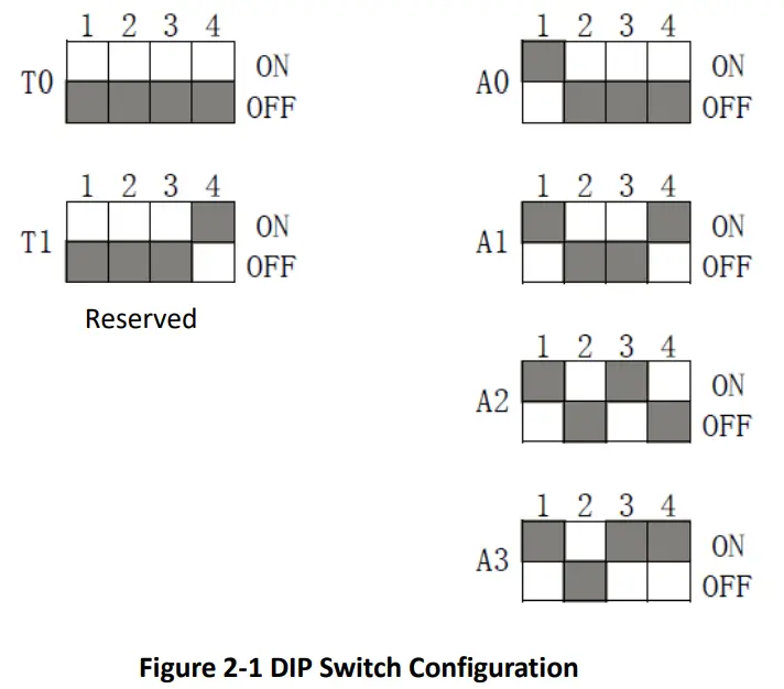
Table 2-2 DIP Switch Configuration
The 4-bit dip switch is used to conTable the anchors and tags of RTLS positioning system. The minimum system of 3D positioning consists of 4 anchors and 1 tag. The first digit represents the current device role (ON means anchor, while OFF means tag), and the last three digits of the DIP switch represents the current device address.
TWR communication protocol
3.1 Structure of positioning frame
The communication data complies with the IEEE 802.15.4 MAC layer frame format. As shown in Table 3-1, A data frame consists of 3 parts-MAC Header (MHR), MAC Payload, and MAC Footer (MFR). MHR consists of frame control bytes, frame sequence number byte and address bytes. The length of MAC payload is variable and can be user-defined. MFR is a 16-bit CRC (FCS) check sequence of MHR and MAC Payload data, which is automatically generated by DW1000.
Table 3-1 Beacon Frame Format
| 2 bytes | 1 byte | 2 bytes | 2 bytes | 2 bytes | Variable length bytes | 2 bytes |
| Frame Control (FC) | Sequence Number | PAN ID | Destination Address | Source Address | Ranging Message | FCS |
| MHR | MAC Payload | MFR | ||||
3.1.1 Frame Control
Table 3-2 Frame Control Type
| Frame Control (FC) | |||||||||||||||
| Bit 0 | Bit 1 | Bit 2 | Bit 3 | Bit 4 | Bit 5 | Bit 6 | Bit 7 | Bit 8 | Bit 9 | Bit10 | Bit11 | Bit12 | Bit13 | Bit14 | Bit15 |
| 1 | 0 | 0 | 0 | 0 | 0 | 1 | 0 | 0 | 0 | 0 | 1 | 0 | 0 | 0 | 1 |
| Frame Type | SEC | PEND | ACK | FIGU RE | Reserved | DestAddrMode | Frame Version | SrcAddrMode | |||||||
Table 3-3 Frame Type
| Frame Type Field (FC bits 2 to 0) | Frame | ||
| 0, | 0, | 0 | Beacon |
| 0, | 0, | 1 | Data |
| 0, | 1, | 0 | Acknowledgement |
| 0, | 1, | 1 | MAC command |
| 1, | 0, | 0 | Reserved |
| 1, | 0, | 1 | Reserved |
| 1, | 1, | 0 | Reserved |
| 1, | 1, | 1 | Reserved |
Table 3-4 DestAddrMode Meaning
| Destination addressing mode (FC bits 11 & 10) | Meaning | |
| 0, | 0 | No destination address or destination PAN ID is present in the frame |
| 0, | 1 | Reserved |
| 1, | 0 | The destination address field is a short (16-bit) address. |
| 1, | 1 | The destination address field is an extended (64-bit) address. |
Table 3-5 SrcAddrMode Meaning
| Destination addressing mode (FC bits 11 & 10) | Meaning | |
| 0, | 0 | No destination address or destination PAN ID is present in the frame |
| 0, | 1 | Reserved |
| 1, | 0 | The destination address field is a short (16-bit) address. |
| 1, | 1 | The destination address field is an extended (64-bit) address. |
3.1.2 Sequence Number
NOTICE: Incremented by 1 for each time.
3.1.3 PAN ID
NOTICE: Data receiving device and data sending device must be the same PAN ID to successfully receive and send data.
3.1.4 Destination Address
NOTICE: N/A
3.1.5 Source Address
NOTICE: N/A
3.1.6 FCS
Frame Check Sequence (FCS)
NOTICE: Data checking, which is automatically calculated by DW1000.
3.1.7 Ranging Message
3.1.7.1 POLL Message
1 byte
Function
Code
0x80
3.1.7.2 Response Message
1 byte
Function
Code
0x81
3.1.7.3 Final Message
| 1 byte | 5 bytes | 5 bytes | 5 bytes |
| Function Code | Poll TX time | Resp RX time | Final TX time |
| 0x82 | – | – | – |
3.1.7.4 Report Message
| 1 byte | 2 bytes |
| Function Code | Distance |
| 0x83 | – |
3.1.7.5 RangeData Message
| 1 byte | 2 bytes | 2 bytes | 2 bytes | 2 bytes | 1 byte |
| Function Code | Distance AO | Distance Al | Distance A2 | Distance A3 | Range Mask |
| 0x84 | – | – | – | – | – |
Serial communication protocol
Example:mc 0f 00000663 000005a3 00000512 000004cb 095f c1 0 a0:0
Table 4-1 Serial Communication Protocol Description
| Content | Example | Description |
| HEAD | mc | Head of the data packet, fixed: ” mc” |
| MASK | Of | If ranging results are valid. For example: mask=0x07(0000 0111) means RANGE 0,1,2 is valid. |
| RANGEO | 663 | Distance from tag to anchor AO, hexadecimal notation, unit: mm, result of the example is 1.635m. |
| RANGE1 | 000005a3 | Distance from tag to anchor Al |
| RANGE2 | 512 | Distance from tag to anchor A2 |
| RANGE3 | 000004cb | Distance from tag to anchor A3 |
| NRANGES | 095f | message flow, accumulated, Ox0-Oxffff |
| RSEQ | cl | Range number, accumulated, Ox0-Oxff |
| DEBUG | 0 | Reserved, for debugging. |
| rlDt:IDa | a0:0 | r means the role: a-anchor, t-tag; IDt-tag address, IDa-anchor address |
Supplementary instruction of rIDt:IDa:
If the current anchor is connected to PC:
r=a indicates the current role is anchor;
IDt indicates the tag ID, and it shows which tag is ranged by the current anchor;
IDa indicates the anchor ID, representing the anchor ID that connecting to the PC
Example:
1, anchor A0 connects to PC, and tag T0 is powered on [a0:0]
2, anchor A0 connects to PC, and tag T1 is powered on [a1:0]
3, anchor A1 connects to PC, and tag T1 is powered on [a1:1]
r=t indicates that it is a tag connecting to PC;
IDt indicates the tag ID, and “:0” is fixed behind the IDt.
Example:
Tag T0 connects to PC, and anchor A0 is powered on [t0:0], then RANGE0 has an output value.
TWR ranging process
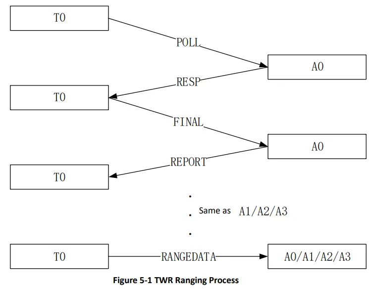
If RangingTag or RangingAnchor program is in process, the entire ranging cycle is completed after TWR ranging from T0 to A0 is executed once.
If RTLS_Tag or RTLS_Anchor program is in process, the entire ranging cycle is completed after finishing the TWR ranging to A0\A1\A2\A3 continuously, and broadcasting a RangeData message.
System deployment
There are two system deployment modes: navigation mode and monitoring mode.
During the navigation mode, the tag needs to be connected to the PC while other anchors only need to power on. The position data and real-time track of the currently connected tag can be displayed on the PC software. In the monitoring mode, one of the anchors is connected to the PC, while the other anchors and labels are powered on. The position data and real-time track of all labels in the coverage area of the current anchor can be displayed in the PC software.
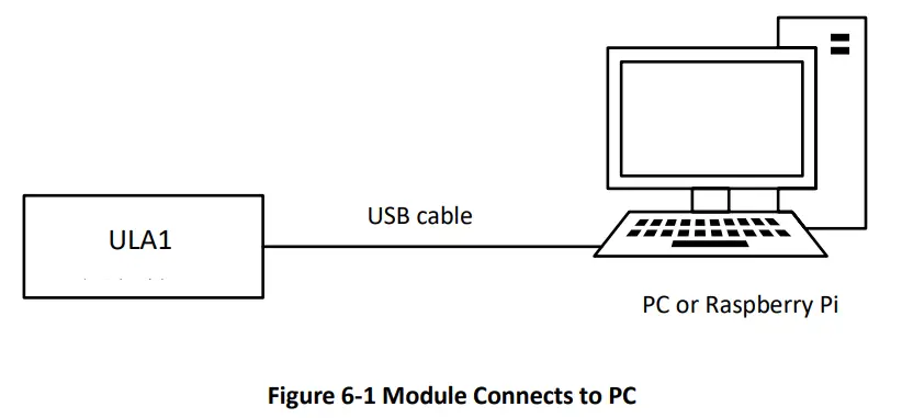
For the initial utilization, CP2102 driver should be installed at first. After identifying the serial port on the PC, please open the PC software, select the serial port, and click “Connect” button to complete module connection and data communication. 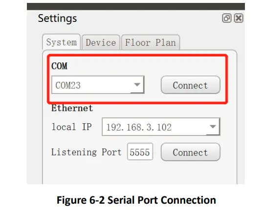
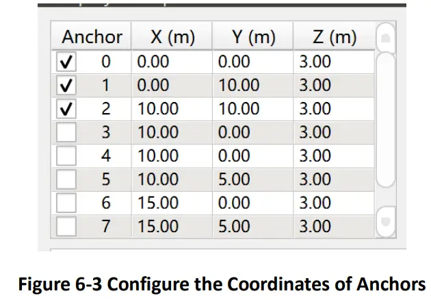
After successfully connecting, users can complete the equipment deployment by configuring the position coordinates of the anchors based on the relative position of the anchors, and then the tags can be located and displayed.
For more details about the utilization of system deployment, please download the <HR-RTLS1 UserManual-EN> to get more information.
Download HR-RTLS1 UserManual:http://rtls1.haorutech.com/download/HR-RTLS1_UserManual-EN.pdf


