Hyfire HFW-TA-05 Wireless Addressable Category P Heat Detector
Product Information
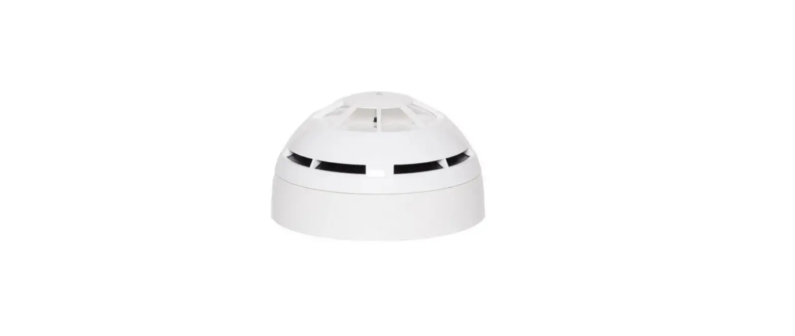
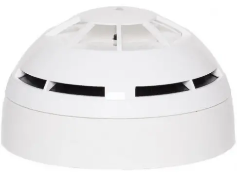
The HFW-TA-05 is a bi-directional wireless addressable category P heat detector that samples the environmental temperature in the protected area. An alarm condition is raised when the level of temperature or the thermal variation rate exceeds the alarm
threshold. This detector is compatible only with wireless systems based on the Sagittarius protocol. It must be installed according to the procedures described in the manual. The detector must NOT be installed near electronic devices and computer equipment that can interfere with its wireless link quality. For more specific information concerning compatibility, refer to your fire security system supplier.
LED Indicators
Before installing the detector, extract the batteries cover from the back of the detector and power up the detector by removing the isolating tab in the battery housing. LED indicators signal Power up. Link the detector to the Sagittarius wireless system (LINKING)
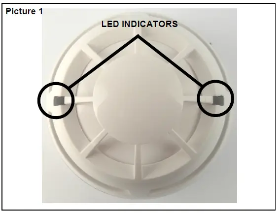
and check the WIRELESS LINK QUALITY. Select a good location for the detector, tag the device’s loop and address data (IDENTIFICATION), and fix the detector supporting base to the wall (BASE INSTALLATION). Picture 1 provides a visual indication for functional conditions and battery levels as indicated in Table 1.
| Detector’s status | LEDs indication |
|---|---|
| Power up | 1 second GREEN, then 4 X 0.5 second RED blink |
| Linking to the system | Blinking GREEN until linking is completed |
| Link failure | RED on (continuous) |
| Normal condition | Blinking RED: 0.5 second on and 0.5 second off |
| Alarm | 0.1 second ORANGE blink, then 5 seconds off |
| Battery 1 fault | 0.1 second GREEN blink, then 5 seconds off |
| Battery 2 fault | 0.1 second ORANGE, then 5 seconds off |
| Both batteries fault | 0.1 second GREEN, then 5 seconds off |
| Another fault | sequential ORANGE / GREEN 0.5 second blinking |
| Tamper | LEDs off |
| Lost link with wire to wireless translator/wireless expander | LEDs off |
Installation Instructions
For detector spacing, placement, and special applications, refer to your specific national standards. Mount the detector as far as possible from metal objects, metal doors, metal window openings, etc., as well as cable conductors, and cables (especially from computers), otherwise, the operating distance may greatly drop. This detector must be installed precisely according to the procedures described in the manual. Test this detector after installation.
Linking Instructions
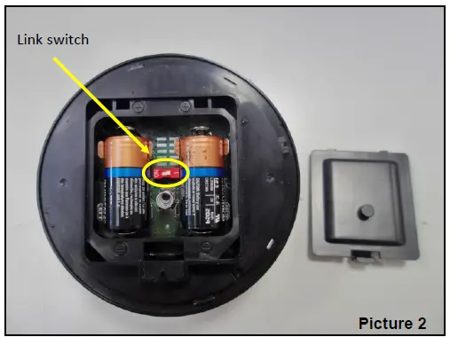
The system is waiting to achieve a wireless child device (For further information, refer to the translator’s or the Wireless configuration software’s literature). Move the link switch’s cursor from ON to the opposite side of its run (we will call it BLANK
since it carries no indication). LED indicators signal Linking to the system (picture 2). Linking is successful when:
- The translator indicates so (check the translator’s literature)
- The Wireless software indicates so (check the Wirelex’s literature)
If linking is unsuccessful, check if evident mistakes were made. Perform the LINKING RECOVERY.
OVERVIEW
This detector model samples the environmental temperature in the protected area. An alarm condition is raised when the level of temperature or the thermal variation rate exceeds the alarm threshold.
COMPATIBILITY
This detector is compatible only with wireless systems based on the Sagittarius protocol. For more specific information concerning compatibility refer to your fire security system supplier.
INSTALLATION – IMPORTANT NOTES
For detector spacing, placement, and special applications refer to your specific national standards. Mount the detector as far as possible from metal objects, metal doors, metal window openings, etc. as well as cable conductors, and cables (especially from computers), otherwise, the operating distance may greatly drop. The detector must NOT be installed near electronic devices and computer equipment that can interfere with its wireless link quality. This detector must be installed according precisely to the procedures described in this manual. Test this detector after installation.
BEFORE INSTALLING THE DETECTOR
- Extract the batteries cover from the back of the detector.
- Power up the detector removing the isolating tab in the battery
housing. LED indicators signal “Power up”. - Link the detector to the Sagittarius wireless system (LINKING).

- Check the WIRELESS LINK QUALITY.
- SELECT A GOOD LOCATION FOR THE DETECTOR.
- Tag the device’s loop and address data (IDENTIFICATION).
- Fix the detector supporting base to the wall (BASE INSTALLATION).
LED INDICATORS
Picture 1: provide a visual indication of functional conditions and battery levels as indicated in Table 1.
| Detector’s status | LEDs indication |
| Power up | 1 second GREEN, then 4 X 0.5 second RED blink |
| Linking to the system | Blinking GREEN until linking is completed |
| Link failure | RED on (continuous) |
| Normal condition | LEDs off |
| Alarm | Blinking RED: 0.5 second on and 0.5 second off |
| Battery 1 fault | 0.1 second ORANGE blink, then 5 seconds off |
| Battery 2 fault | 0.1 second GREEN blink, then 5 seconds off |
| Both batteries fault | 0.1 second ORANGE, then 5 seconds off 0.1 second GREEN, then 5 seconds off |
| Other fault | sequential ORANGE / GREEN 0.5 second blinking |
| Tamper | LEDs off |
| Lost link with wire to wireless translator / wireless expander | LEDs off |
LINKING
The system is waiting to achieve a wireless child device (for further information refer to the translator’s or the Wirelex configuration software’s literature):
- Move the link switch’s cursor from ON to the opposite side of its run (we will call it BLANK since it carries no indication). LED indicators signal “Linking to the system” (picture 2).
Linking is successful when: the translator indicates so (check the translator’s literature)
OR
the Wirelex software indicates so (check the Wirelex’s literature). If linking is unsuccessful: - Check if evident mistakes were made.
- Perform the LINKING RECOVERY.
| Communication quality | Assessment | Device’s indication |
| No communication | Fail | Two red blinks |
| Communication quality: 0 dB – 10 dB (Mark 2) | Poor, not acceptable | One red blink |
| Communication quality: 10 dB – 20 dB (Mark 3) | Medium-low, not recommended | One green blink |
| Communication quality: 20 dB – 30 dB (Mark 4) | Good | Two green blinks |
| Communication quality: > 30 dB (Mark 5) | Excellent | Two green blinks |
LINKING RECOVERY
- Take out both batteries from their holders
- Move alternatively the link switch to ON / BLANK five times (picture 2)
- Move the link switch to ON
- Reinsert both batteries into their holders, oriented as per polarity marks
- Perform the LINKING procedure

DETECTOR SENSITIVITY SETTINGS
During installation using the Wirelex software, it’s possible to set the heat category of the detector (see Table 4). Otherwise, if the installation is performed manually through the translator keyboard, the default setting will be applied.
WIRELESS LINK QUALITY
It is possible to check the wireless link quality between the detector and its linked-to translator or expander in this way
- Move the link switch to the ON position.

- LED indicators will start blinking according to the following table
NOTE: Ensure the link switch is returned to the “BLANK” (operational) position on completion of testing.
SELECT A GOOD LOCATION FOR THE DETECTOR
Choose for the detector a placement position that:
- compliances with your specific standards

- is reached by a strong wireless signal from its linked-to translator or expander module
- is not interfered with by environmental factors.
IDENTIFICATION
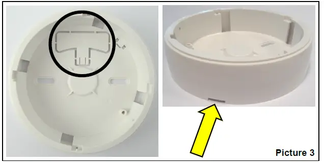
For identification purposes, the analog loop number and the device’s address can be recorded on the plastic tag supplied with the base (picture 3). Extract the plastic tag from the bottom of the base, write or label identification data on it and, finally, insert it in the side slot of the base.
BASE INSTALLATION
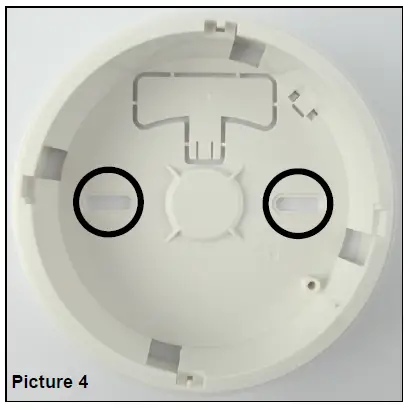
Fix the base to the wall with the provided screws (picture 4).
DETECTOR PLACEMENT
- Install the batteries cover.
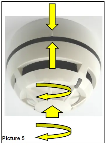
- Position the detector centrally on the base ensuring it is level.
- Rotate clockwise applying gentle pressure. The detector will drop into its keyed location.
- Continue to rotate clockwise a few degrees until the detector has fully engaged in the base.
- When the detector is firmly engaged, check the alignment of the raised reference marks on the detector and on the base (picture 5).
DETECTOR LOCKING
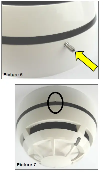
To lock the detector to the base, screw in the provided security screw; the screw entry is located on the side of the detector’s base (picture 6).
TAMPER DETECTION
When the detector is detached from the base a tamper message event is sent to the control panel.
TESTING
Test this detector after installation. After each test reset the fire security system from the control panel, as per your control panel instructions.
TEST 1 – MAGNET TEST
- Hold a suitable magnet in correspondence with the indicated area (picture 7).
- Wait a few seconds.
- If it works LED indicator will signal “Alarm”.
TEST 2 – HEAT TEST
Use only suitable heat test devices from approved manufacturers.
- By following its specific instructions, apply the heat test device to the detector.
- Wait a few seconds.
- If it works LED indicator will signal “Alarm”.
Dust covers DO NOT provide complete protection against contamination: detectors should be removed before construction, major re-decoration, or other dust-producing work is started. Dust covers MUST be removed before the system can be made operational During the linking phase, the detector must be positioned close to the aerial (within a few centimeters) of the translator or expander to which it is being linked.
MAINTENANCE – CLEANING
- Remove the detector from its base.
- Thermistor area: use a small, soft bristle brush to dislodge any obvious contaminants such as insects, spider webs, hairs, etc.
- Thermistor area: use a small vacuum tube or dry, clean, compressed air to suck up or blow any remaining small particles away.
- Wipe the exterior housing of the detector with a clean, damp, lint-free cloth to remove any surface film that can later attract airborne contaminants.
- Install the detector onto its base again.
- Test the detector.
MAINTENANCE – BATTERY REPLACEMENT
When a low battery condition is indicated, both batteries must be changed altogether.
During this procedure, the linking switch must NOT be touched at all!
- Detach the detector from its base.
- Extract the batteries cover.
- Extract the batteries.
- Insert the new batteries into their holders, oriented as per polarity marks.
- Reinstall the batteries cover.
- Reinstall the detector onto its base.
- Test the detector.
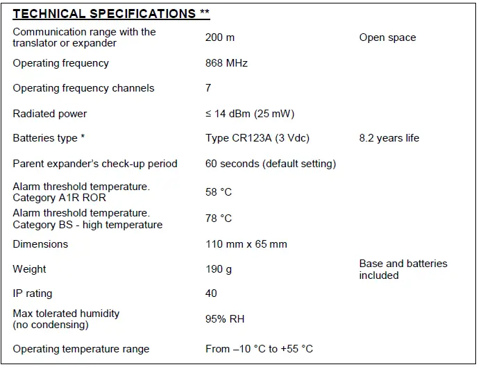
TECHNICAL SPECIFICATIONS
NOTE OF THE DOCUMENT
Hyfire Wireless Fire Solutions hereby declares that this detector is in compliance with the essential requirements and other relevant provisions of Directive 1999/5/EC. A copy of the original Declaration of Conformity (Document: DoC LI01) is made available to the user on the website: www.argussecurity.iWhen a low battery condition is indicated, both batteries must be changed for new cells. The lifespan of the batteries indicated is subject to standard environmental conditions, default monitor settings, and excellent link quality. Check the latest version of document TDS-LHTXX for further data, obtainable from your supplier.
| THERMAL SENSITIVITY (EN 54) | ||
| Detector Category | Wirelex setting | Notes |
| A1R | A1R | default |
| BS | High temperature | |
WARNINGS AND LIMITATIONS
Our devices use high-quality electronic components and plastic materials that are highly resistant to environmental deterioration. However, after 10 years of continuous operation, it is advisable to replace the devices in order to minimize the risk of reduced performance caused by external factors. Ensure that this device is only used with compatible control panels. Detection systems must be checked, serviced, and maintained on a regular basis to confirm correct operation. Smoke detectors may respond differently to various kinds of smoke particles, thus application advice should be sought for special risks. Detectors cannot respond correctly if barriers exist between them and the fire location and may be affected by special environmental conditions. Refer to and follow national codes of practice and other internationally recognized fire engineering standards. Appropriate risk assessment should be carried out initially to determine the correct design criteria and updated periodically.
WARRANTY
All devices are supplied with the benefit of a limited 5 years warranty relating to faulty materials or manufacturing defects, effective from the production date indicated on each product. This warranty is invalidated by mechanical or electrical damage caused in the field by incorrect handling or usage. The product must be returned via your authorized supplier for repair or replacement together with full information on any problem identified. Full details on our warranty and product’s returns policy can be obtained upon request.Hyfire Wireless Fire Solutions Limited – Unit B12a, Holly Farm Business Park, Honiley, Warwickshire, CV8 1NP – United Kingdom EN 54-5:2017+A1:2018
EN 54-25:2008
Category P
HFW-TA-05
For use in compatible fire detection and alarm system


