
Laserliner SensoLite 310 Laser Receiver User Manual
Read the operating instructions and the enclosed brochure “Guarantee and additional notices” completely. Follow the instructions they contain. Safely keep these documents for future reference.
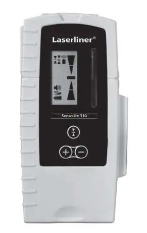
Laser receiver for red and green rotary lasers
- One LCD on the front and one on the rear
- Five-digit display, various acoustic melodies support the optical indicators
- Extremely loud piezo buzz tone possible
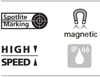
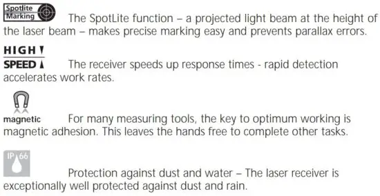
- Head and side magnets
- Reception range 300 m for red lasers, 200 m for green lasers
- Extremely durable design
Special product features
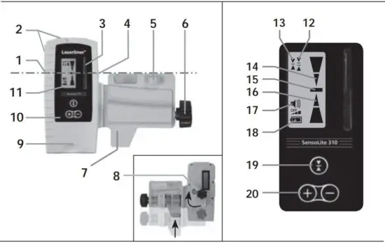
- All-round marking groove
- Magnets
- Receiver field for laser beam
- SpotLite Marking LED
- Vial
- Fastening screw for levelling staffs
- Universal mount
- Binding screw / loudspeaker (rear side)
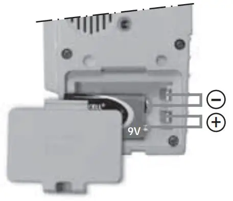
- Battery compartment (rear side)
- Control panel
- LC-Displays (front and rear side)
- Free-hand range
- Fine range
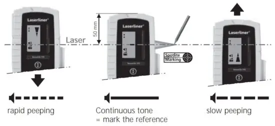
- Hand receiver above laser level
- Precisely on laser level
- Hand receiver below laser level
- Volume indicator
- Low battery indicator
- Switch on /
Hand receiver mode /
Switch: Precision range /
Free-hand range
Switch off:
press button 3 seconds - Volume adjustment
Inserting the battery
In order to preserve the battery life, the receiver switches off automatically if it is not used for around 5 minutes.
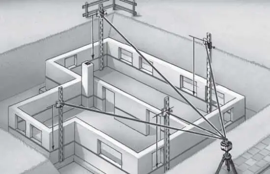
Working with the laser receiver
Set the rotary laser to maximum speed and switch the laser receiver on. It is able to detect the laser beam at a great distance now. Move the SensoLite up and down through the laser beam until the middle indicator (15) appears. Mark the measured height at the perimeter marking groove.
The laser receiver has two tolerance settings:
- Free-hand range (12): Display with larger tolerance for rough alignment by hand.
- Precision range (13): Display with smaller tolerance for precision alignment (e.g. levelling staff).
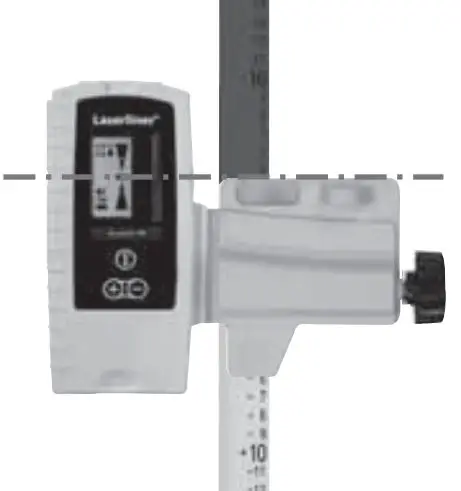
Universal mount
The laser receiver can be installed on levelling staffs with the aid of the universal mount. The Flexi measuring staff (Order number 080.50 – red / 080.51 – green) is always recommended when measuring from floor heights. It also allows you to determine heights directly without any need for calculation.
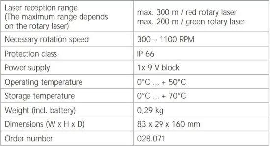
Technical data
(Subject to technical alterations)
EU directives and disposal
This device complies with all necessary standards for the free movement of goods within the EU.
This product is an electric device and must be collected separately for disposal according to the European Directive on waste electrical and electronic equipment.
Further safety and supplementary notices at: www.laserliner.com/info
![]()
![]()
SERVICE
Umarex GmbH & Co KG
– Laserliner –
Möhnestraße 149, 59755 Arnsberg, Germany
Tel.: +49 2932 638-300, Fax: +49 2932 638-333
[email protected]
Umarex GmbH & Co KG
Donnerfeld 2
59757 Arnsberg, Germany
Tel.: +49 2932 638-300, Fax: -333
www.laserliner.com
Read More About This Manual & Download PDF:


