![]() voidacoustics.com
voidacoustics.com  Bias D1/Q1/Q1.5/Q2
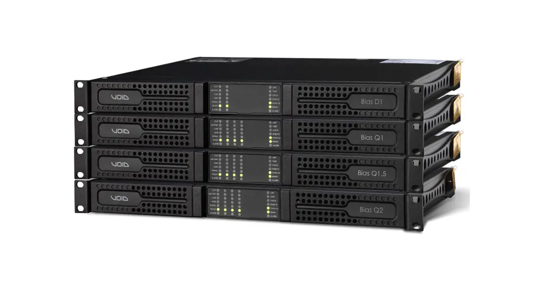
Powering the future of sound
USER GUIDE V3.0
©2022 Void Acoustics Research Ltd.
This user guide is subject to change without notice.
For the latest online version, visit: www.voidacoustics.com
Void Acoustics and the Void logo are registered trademarks of Void Acoustics Research Ltd. in the United Kingdom, USA and other countries; all other Void trademarks are the property of Void Acoustics Research Ltd.
Important Safety Instructions
Common symbols and meanings![]() THE TRIANGLE WITH THE LIGHTNING BOLT IS USED TO ALERT THE USER TO THE RISK OF ELECTRIC SHOCK.
THE TRIANGLE WITH THE LIGHTNING BOLT IS USED TO ALERT THE USER TO THE RISK OF ELECTRIC SHOCK.![]() THE TRIANGLE WITH THE EXCLAMATION POINT IS USED TO ALERT THE USER TO IMPORTANT OPERATING OR MAINTENANCE INSTRUCTIONS.
THE TRIANGLE WITH THE EXCLAMATION POINT IS USED TO ALERT THE USER TO IMPORTANT OPERATING OR MAINTENANCE INSTRUCTIONS.![]() THE CE-MARK INDICATES THE COMPLIANCE OF THE PRODUCT TO ALL THE APPLICABLE EUROPEAN DIRECTIVES
THE CE-MARK INDICATES THE COMPLIANCE OF THE PRODUCT TO ALL THE APPLICABLE EUROPEAN DIRECTIVES![]() SYMBOL FOR EARTH/GROUND CONNECTION.
SYMBOL FOR EARTH/GROUND CONNECTION.![]() SYMBOL INDICATING THAT THE EQUIPMENT IS FOR INDOOR USE ONLY.
SYMBOL INDICATING THAT THE EQUIPMENT IS FOR INDOOR USE ONLY.![]() SYMBOL FOR CONFORMITY WITH DIRECTIVE 2012/19/EC OF THE EUROPEAN PARLIAMENT ON WASTE ELECTRICAL AND ELECTRONIC EQUIPMENT (WEEE).
SYMBOL FOR CONFORMITY WITH DIRECTIVE 2012/19/EC OF THE EUROPEAN PARLIAMENT ON WASTE ELECTRICAL AND ELECTRONIC EQUIPMENT (WEEE).
Safety Warnings![]() OPERATING TEMPERATURE RANGE: 0°C TO +35°C – DERATING ABOVE 35°C.
OPERATING TEMPERATURE RANGE: 0°C TO +35°C – DERATING ABOVE 35°C.![]() STORAGE RELATIVE HUMIDITY RANGE: 10% TO 85% HUMIDITY (NON CONDENSING).
STORAGE RELATIVE HUMIDITY RANGE: 10% TO 85% HUMIDITY (NON CONDENSING).![]() DO NOT USE THE UNIT AT ALTITUDES ABOVE 2000 M.
DO NOT USE THE UNIT AT ALTITUDES ABOVE 2000 M.![]() DO NOT USE THE UNIT IN TROPICAL ENVIRONMENT
DO NOT USE THE UNIT IN TROPICAL ENVIRONMENT![]() TO REDUCE THE RISK OF ELECTRIC SHOCK, DO NOT ATTEMPT TO OPEN ANY PART OF THE UNIT. NO USER-SERVICEABLE PARTS INSIDE. REFER SERVICING TO QUALIFIED SERVICE PERSONNEL.
TO REDUCE THE RISK OF ELECTRIC SHOCK, DO NOT ATTEMPT TO OPEN ANY PART OF THE UNIT. NO USER-SERVICEABLE PARTS INSIDE. REFER SERVICING TO QUALIFIED SERVICE PERSONNEL.![]() CONNECTION TO THE MAINS SHALL BE DONE ONLY BY A ELECTROTECHNICAL SKILLED PERSON ACCORDING THE NATIONAL REQUIREMENTS OF THE COUNTRIES WHERE THE UNIT IS SOLD.
CONNECTION TO THE MAINS SHALL BE DONE ONLY BY A ELECTROTECHNICAL SKILLED PERSON ACCORDING THE NATIONAL REQUIREMENTS OF THE COUNTRIES WHERE THE UNIT IS SOLD.![]() DO NOT USE THIS AMPLIFIER IF THE ELECTRICAL POWER CORD IS FRAYED OR BROKEN.
DO NOT USE THIS AMPLIFIER IF THE ELECTRICAL POWER CORD IS FRAYED OR BROKEN.![]() TO AVOID ELECTRICAL SHOCK, DO NOT TOUCH ANY EXPOSED SPEAKER WIRING WHILE THE AMPLIFIER IS OPERATING.
TO AVOID ELECTRICAL SHOCK, DO NOT TOUCH ANY EXPOSED SPEAKER WIRING WHILE THE AMPLIFIER IS OPERATING.![]() DO NOT SPILL WATER OR OTHER LIQUIDS INTO OR ON THE AMPLIFIER.
DO NOT SPILL WATER OR OTHER LIQUIDS INTO OR ON THE AMPLIFIER.![]() THIS DEVICE MUST BE POWERED EXCLUSIVELY BY EARTH CONNECTED MAINS SOCKETS IN ELECTRICAL NETWORKS COMPLIANT TO THE IEC 364 OR SIMILAR RULES
THIS DEVICE MUST BE POWERED EXCLUSIVELY BY EARTH CONNECTED MAINS SOCKETS IN ELECTRICAL NETWORKS COMPLIANT TO THE IEC 364 OR SIMILAR RULES![]() DISCONNECT THE AC MAINS SOURCE BEFORE ATTEMPTING TO CLEAN ANY PART OF THE AMPLIFIER
DISCONNECT THE AC MAINS SOURCE BEFORE ATTEMPTING TO CLEAN ANY PART OF THE AMPLIFIER![]() VOID SUGGESTS TO PLUG THE BIAS D1/Q1/Q2 SERIES TO A 16 A RATING, C OR D CURVE, 10 kA SECTIONING BREAKER.
VOID SUGGESTS TO PLUG THE BIAS D1/Q1/Q2 SERIES TO A 16 A RATING, C OR D CURVE, 10 kA SECTIONING BREAKER.![]() OUTPUT TERMINALS ARE HAZARDOUS: WIRING CONNECTION TO THESE TERMINALS REQUIRES INSTALLATION BY AN INSTRUCTED
OUTPUT TERMINALS ARE HAZARDOUS: WIRING CONNECTION TO THESE TERMINALS REQUIRES INSTALLATION BY AN INSTRUCTED ![]() PERSON AND THE USE OF READY MADE LEADS
PERSON AND THE USE OF READY MADE LEADS![]() PROPERLY FIT THE AC MAINS PLUG TO THE AMPLIFIER INLET.
PROPERLY FIT THE AC MAINS PLUG TO THE AMPLIFIER INLET.![]() BEFORE POWERING THIS AMPLIFIER, VERIFY THAT THE CORRECT VOLTAGE RATING IS BEING USED.
BEFORE POWERING THIS AMPLIFIER, VERIFY THAT THE CORRECT VOLTAGE RATING IS BEING USED.![]() TAKE CARE TO LOCK THE OUTPUT TERMINAL BEFORE SWITCHING THE DEVICE ON.
TAKE CARE TO LOCK THE OUTPUT TERMINAL BEFORE SWITCHING THE DEVICE ON.![]() VERIFY THAT YOUR MAINS CONNECTION IS CAPABLE OF SATISFYING THE POWER RATINGS OF THE DEVICE.
VERIFY THAT YOUR MAINS CONNECTION IS CAPABLE OF SATISFYING THE POWER RATINGS OF THE DEVICE.![]() NO NAKED FLAME SOURCES SUCH AS LIGHTED CANDLES SHOULD BE PLACED ON THE AMPLIFIER.
NO NAKED FLAME SOURCES SUCH AS LIGHTED CANDLES SHOULD BE PLACED ON THE AMPLIFIER.![]() IT IS HIGHLY RECOMMENDED TO UNPLUG THE OUTPUT CONNECTORS BEFORE PROCEEDING WITH THE SELF CHECK PROCEDURE
IT IS HIGHLY RECOMMENDED TO UNPLUG THE OUTPUT CONNECTORS BEFORE PROCEEDING WITH THE SELF CHECK PROCEDURE
THE TESTING SIGNALS MIGHT CAUSE LOUDSPEAKER IMPAIRMENTS.![]() TO PREVENT INJURY, THIS APPARATUS MUST BE SECURELY RACK MOUNTED IN ACCORDANCE WITH THE INSTALLATION INSTRUCTIONS.
TO PREVENT INJURY, THIS APPARATUS MUST BE SECURELY RACK MOUNTED IN ACCORDANCE WITH THE INSTALLATION INSTRUCTIONS.![]() THIS EQUIPMENT SHALL BE MOUNTED AT A MAXIMUM HEIGHT OF 2 M THE MANUFACTURER CANNOT BE HELD RESPONSIBLE FOR DAMAGES CAUSED
THIS EQUIPMENT SHALL BE MOUNTED AT A MAXIMUM HEIGHT OF 2 M THE MANUFACTURER CANNOT BE HELD RESPONSIBLE FOR DAMAGES CAUSED![]() TO PERSONS, THINGS OR DATA DUE TO AN IMPROPER OR MISSING GROUND CONNECTION.
TO PERSONS, THINGS OR DATA DUE TO AN IMPROPER OR MISSING GROUND CONNECTION.![]() IT IS ABSOLUTELY NECESSARY TO VERIFY THESE FUNDAMENTAL REQUIREMENTS OF SAFETY AND, IN CASE OF DOUBT, REQUIRE AN ACCURATE CHECK BY QUALIFIED PERSONNEL.
IT IS ABSOLUTELY NECESSARY TO VERIFY THESE FUNDAMENTAL REQUIREMENTS OF SAFETY AND, IN CASE OF DOUBT, REQUIRE AN ACCURATE CHECK BY QUALIFIED PERSONNEL.
![]() CAUTION
CAUTION ![]()
RISK OF ELECTRICAL SHOCK-DO NOT OPEN
Please read and keep all safety and use instructions.
This product is intended for installation by professional installers only!
This document is intended to provide professional installers with basic installation and safety guidelines for this product in typical fixed-installation systems. Please read this document and all safety warnings before attempting installation.
- Read these instructions.
- Keep these instructions.
- Heed all warnings.
- Follow all instructions.
- Do not use this equipment near water.
- Clean only with a dry cloth.
- Do not block any ventilation openings. Install in accordance with the manufacturer’s instructions.
- Do not install near any heat sources such as radiators, heat registers, stoves, or other apparatus that produce heat.
- Do not defeat the safety purpose of the polarized or grounding-type plug. A polarized plug has two blades with one wider than the other. A grounding-type plug has two blades and a third grounding prong. The wide blade or the third prong are provided for your safety. If the provided plug does not fit into your outlet, consult an electrician for replacement of the obsolete outlet.
- Protect the power cord from being walked on or pinched particularly at plugs, convenience receptacles, and the point where they exit from the apparatus.
- Only use attachments/accessories specified by the manufacturer.
 Use only with the cart, stand, tripod, bracket, or table specified by the manufacturer, or sold with the apparatus.
When a cart is used, use caution when moving the cart/ apparatus combination to avoid injury from tip-over.- Unplug this apparatus during lightning storms or when unused for long periods of time.
- Refer all servicing to qualified service personnel. Servicing is required when the apparatus has been damaged in any way, such as powersupply cord or plug is damaged, liquid has been spilled or objects havefallen into the apparatus, the apparatus has been exposed to rain ormoisture, does not operate normally, or has beendropped.
Regulatory Compliance Statements
Europe![]() If the time arises to dispose of your product, please recycle all possible component.
If the time arises to dispose of your product, please recycle all possible component.
This symbol indicates that when the end-user wishes to discard this product, it must be sent to separate collection facilities for recovery and recycling. By separating this product from other householdtype waste, the volume of waste sent to incinerators or land-fills will be reduced and natural resources will thus be conserved.
The Waste Electrical and Electronic Equipment Directive (WEEE Directive) aims to minimise the impact of electrical and electronic goods on the environment. Powersoft S.p.A. comply with the Directive 2012/19/EU of the European Parliament on waste electrical finance the cost of treatment and recovery of electronic equipment (WEEE) in order to reduce the amount of WEEE that is being disposed of in land-fill site.
All of our products are marked with the WEEE symbol; this indicates that this product must NOT be disposed of with other waste. Instead it is the user’s responsibility to dispose of their waste electrical and electronic equipment by handing it over to an approved reprocessor, or by returning it to Powersoft S.p.A. for reprocessing. For more information about where you can send your waste equipment for recycling, please contact Powersoft S.p.A. or one of your local distributors.
USA
FCC Supplier’s Declaration of Conformity
Responsible Party:
Powersoft S.p.A.
Via Enrico Conti, 5
50018 Scandicci (FI) – Italy
Phone: +39 055 735 0230
Fax: +39 055 735 6235
FCC Compliance Statement
This device complies with part 15 of the FCC rules. Operation is subject to the following two conditions:
1) This device may not cause harmful interference, and 2) this device must accept any interference received, including interference that may cause undesired operation.
CAUTION: Changes or modifications not expressly approved by the party responsible for compliance could void the user’s authority to operate the equipment.
NOTE: This equipment has been tested and found to comply with the limits for a Class A digital device, pursuant to part 15 of the FCC Rules. This equipment generates, uses, and can radiate radio frequency energy and, if not installed and used in accordance with the instruction manual, may cause harmful interference to radio communications. However, there is no guarantee that interference will not occur in a particular installation. If this equipment does cause harmful interference to radio or television reception, which can be determined by turning the equipment off and on, the user is encouraged to try to correct the interference by one or more of the following measures:
- Reorient or relocate the receiving antenna.
- Increase the separation between the equipment and receiver.
- Connect the equipment into an outlet on a circuit
- Different from that to which the receiver is connected.
WARNING: This is a class A product. In a domestic environment this product may cause radio interference in which case the user may be required to take adequate measures
Canada
Canadian Caution
This device contains licence-exempt transmitter(s)/receiver(s) that comply with Innovation, Science and Economic Development Canada’s licenceexempt RSS(s). Operation is subject to the following two conditions: 1)This device may not cause interference. 2)This device must accept any interference, including interference that may cause
undesired operation of the device.
WARNING: This is a class A product. In a domestic environment this product may cause radio interference in which case the user may be required to take adequate measures ICES-003 Class A Notice This Class A digital apparatus complies with Canadian ICES-003. Radiation Exposure Statement
This equipment complies with RSS-102 radiation exposure limits set forth for an uncontrolled environment. This equipment should be installed and operated with minimum distance 20cm between the radiator & your body.
EC declaration of conformity
For EC Declaration of Conformity please go to: www.voidacoustics.com/eu-declaration-amplifiers
UKCA marking
For details of the UKCA marking go to: www.voidacoustics.com/uk-declaration-amplifiers
Warranty statement
For warranty statement go to: https://voidacoustics.com/terms-conditions/
Preliminary operations
Package list
The box contains the following:
1x Bias D1 amplifier.
1x Phoenix MC 1,5/4-ST-3,81 – 1803594 plug
2x Phoenix MC 1,5/6-ST-3,81 – 5447900 plug
1x Phoenix PC 5/4-STF1-7,62 – 177859 plug
1x IEC power cord
1x User guide
OR
1x Bias Q1/Q1.5/Q2 amplifier.
1x Phoenix MC 1,5/4-ST-3,81 – 1803594 plug
2x Phoenix MC 1,5/12-ST-3,81 – 1803675 plug
1x Phoenix PC 5/8-STF1-7,62 – 177891 plug
1x IEC power cord
1x User guide
Location
Install your Bias Amplifier in well ventilated rack cabinets.
Secure both front and rear brackets to the rack.
Connect the AC Mains connector to a circuit breaker.
Install the amplifier far from EMF emitting devices.
Avoid placing the amplifier close to heat generating sources.
Cooling
The ventilation openings must not be impeded by any item, keep a distance of at least 50 cm from the front and rear ventilation openings of the amplifier.
Bias implements a forced-air cooling system to maintain constant operating temperatures. Air enters from the front panel, exiting at the back of the amplifier.
The cooling system features variable-speed DC fans controlled by the heat sink mounted sensors. This ensures that fan noise and internal dust accumulation are kept to a minimum. In the rare event of overheating, sensing circuits shut down all channels until the amplifier cools down to a safe operating temperature. Normal operation is resumed automatically without the need for user intervention.
Bias amplifiers can be stacked one on top of the other, leave one rack unit empty every four to guarantee adequate air flow.
Cleaning
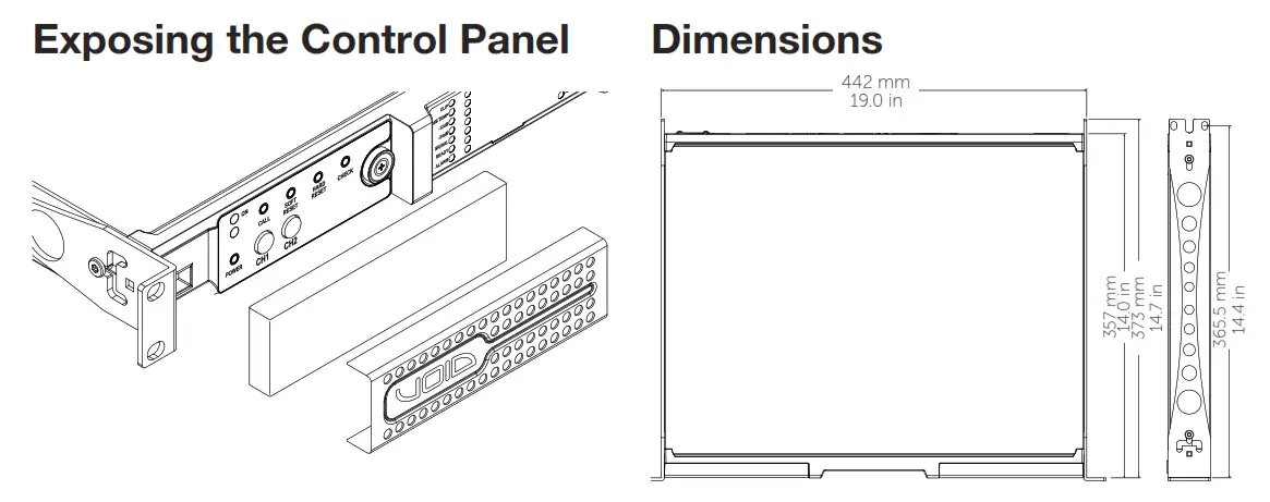
Use a dry cloth for cleaning the chassis and the front panel. Air filter cleaning should be scheduled in accordance with the dust levels in the amplifier’s operating environment.
In order to clean the vent filters remove the front cover by firmly gripping the outermost silver panels and pull them outwards Use compressed air to remove the dust from filters, or wash it with clean water (let the filter dry thoroughly before reinstalling them).
AC Mains Supply
Bias amplifiers implement an universal switching mode power supply with power factor correction operating in the range from 100 VAC up to 240 VAC ±10%.
AC mains connection is in the rear panel through the IEC C20 inlet, the approved power cord is provided. Switching the amplifier On and Off
Once properly powered (power cord inserted, sectioning breaker closed), the system can be either ON or in
STANDBY mode depending on its state at latest power off.
In order to toggle the amplifier between ON and STANDBY keep pressed the power button for 3 seconds. Please consider that the operating condition can be modified by
the REMOTE ON and REMOTE OFF configuration.
Energy Save
The Smart Rails Management technology implemented in the power supply unit allows to reduce the power consumption when the input signal falls under a defined threshold. When On, Energy Save is active on each channel independently. If the signal is missing for more than 30 minutes on all channels, the auto standby is applied and the main PSU is turned off to further save energy (Time out time is selectable via Armonía in Dante™ Enabled Versions). Normal operation is resumed in a matter of milliseconds when an incoming signal is detected.
In order to activate the Energy Save feature, operate the NRG SAVE dip switch on the rear panel.
Breaker Save
This feature may be activated when the power grid is unable to provide enough current to continuously drive the loads, or when the number of amplifier connected to the same outlet is such that one can reach the critical power absorption of the line. When activated, the Breaker Save halves the maximum continuous current absorption from the mains. This slightly reflects on the overall performance of the system, reducing the available output power.
In order to activate the Breaker Save feature, locate the BRK SAVE switch on the rear panel.
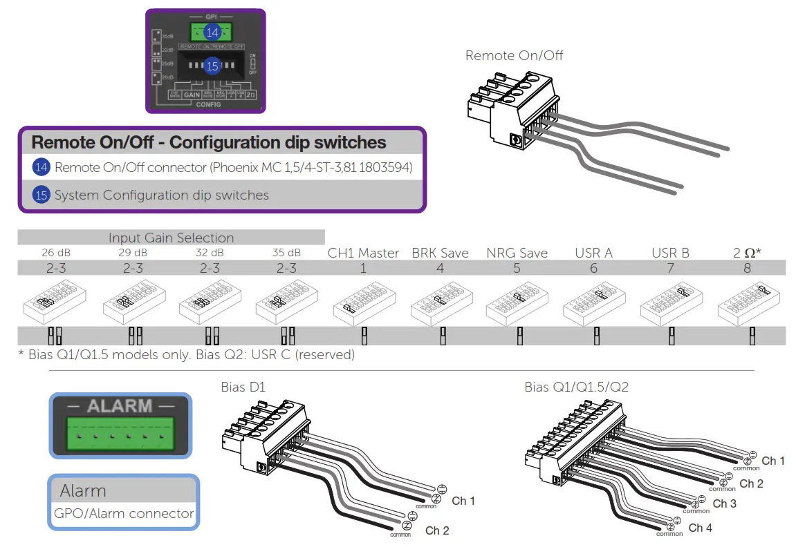
Remote On/Off
Remote ON/OFF is available through the dedicated terminals on the rear panel. Both terminals respond to the differential voltage between the contacts: a voltage difference in the range 5 VDC – 24 VDC triggers the control. Any voltage exceeding 28 VDC may damage the input circuitry.
The couple of terminals act depending on the actual state of the amplifier, in accordance with the following table.
| REMOTE ON | REMOTE OFF | AMPLIFIER STATE |
| Vdiff ≥ 5V | Any | Force Turn ON |
| Vdiff < 3V | Vdiff ≥ 5V | Force Turn OFF |
| Vdiff < 3V | Vdiff < 3V | No Change (Keep either standby or in current state) |
Gain selection
The Bias amplifiers can operate with different gain applied to the input signal. This feature is designed to match the voltage of the input signal.
A proper combination of the position of two GAIN switches on the rear panel sets the operating gain of the amplifier Connections
Signal Grounding
There is no ground switch or terminal on the Bias Series amplifiers. The unit’s signal grounding system is automatic. In order to limit hum and/or interference entering the signal path, use balanced input connections.
In the interests of safety, the unit MUST always operate with electrical safety earth connected to the chassis via the dedicated Protective Earth wire.
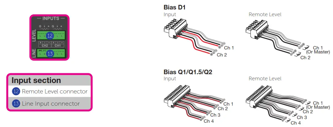
Analog Audio Input connections
Analog input connections are made via the Phoenix MC 1,5/6-ST-3,81 5447900 connector.
Remote Level adjustment
The level of each channel can be remotely adjusted by means of a linear 10 kΩ potentiometer connected to the input LEVEL connector.
When the CH1 MSTR switch is in the OFF position the remote level potentiometers work independently on each separate channel. When the CH1 MSTR switch is in the ON position the remote level potentiometer of channel 1 acts as a master level, controlling the volume of both channels.
The remote level controls are in series with the level adjustment knobs in the front panel.
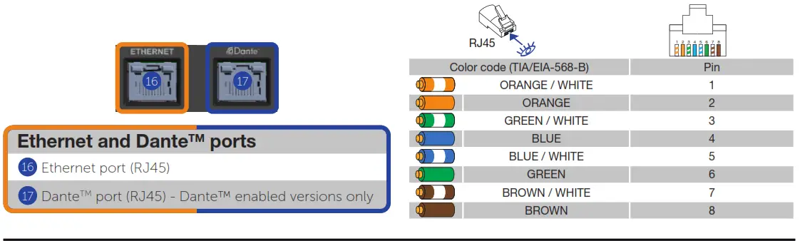
Digital Audio Input connection
Dante TM enabled models accepts two or four (model dependant) input streams from the Dante TM connection through the Dante TM port. Cabling must comply to TIA/EIA-568-B and adopt the T568B scheme pinout. In order to implement a Dante TM network, a computer running Dante TM Controller should to be used. Dante TM Controller is a software application that manages devices on the network. Dante™ enabled Bias amplifiers are automatically discovered and displayed in Dante TM Controller with the default identifier: MODELNAME-SERIAL (e.g. BiasD1-71520).
Ethernet connection
The port labelled Ethernet is designed to remotely control the amplifier via an Ethernet connection through a personal computer and ArmoníaPlus software.
Void recommend the use of Ethernet Cat5 straight through – patch – cables with pin/pair assignments TIA/EIA-568-B, i.e. T568B. Output connections
Output connections are made via the Phoenix PC 5/4-STF17,62 177859 port. Any mixed configuration of low and high impedance output loads can be made: in order to set the load configuration, each channel is provided with four DIP switches.
Hi-Z 70V/100V operations
Any channel of can drive 70V/100V (Hi-Z) distributed line loudspeakers. In order to connect any channel’s output to a 70V/100V line, the rear panel DIP switch corresponding to the channel must be set.
Void recommends to use the built-in HPF (High Pass Filter) when the amplifier is set to drive a distributed line to prevent loudspeaker transformer saturation, which can considerably degrade sound performance. The HPF can be activated by means of the DIP switch corresponding to the channel, two cutting frequency are available 35 Hz and 70 Hz.
Lo-Z 2Ω load operation
Bias Series amplifiers are optimized for working with 4Ω output loads but a special configuration allows to connect low loads down to 2Ω. The 2Ω switch allows to activate on all output channels set to match low impedance (i.e. in Lo-Z configuration) an operating condition that optimizes the performance with very low loads, by limiting the
maximum output voltage to 85 Vpeak per channel.
For optimal 2Ω performance, it is recommended to select LowZ mode for all the amplifier’s channels.
Diagnostics – GPO – Alarms
Bias Series provides a pair of paralleled general purpose output connections per channel: one Normally Open NO and one Normally Closed NC.
The connections are available on the back panel via the 6-pin Phoenix MC 1.5/6-ST-3.81 5447900 connector.
When the amplifier is in normal operating condition the NO contacts are closed, whilst the NC contacts are open, and vice-versa. These contacts are used to report potentially dangerous faults or generally unsafe operation conditions by toggling alarm switches relative to the following events, and any fault preventing the normal
operation of an output channel:
No AC mains (i.e. system shutdown); Thermal stress: the system temperature is too high and the thermal protection is engaged;
Short circuit in output wiring: either the loudspeaker or the line is in short;
Amplifier is in Standby
Dante™ versions feature further monitoring on pilot tone and output
load trough ArmoníaPlus.
Self Check
The self check procedure tests the amplifier status and reports the user in case of failures. After few minutes, at the end of the self check procedure, a combination of lit LED in the LED panel provides information about the amplifier status.
In order to exit the self check test and resume normal operations, press once the self check push button 6 .
If self check cannot be started because of a fault, the check LED will blink fast, whilst a reassuring slow blink is an indication of a completed self check procedure.
Pilot Tone monitoring
The detection of a mismatch in the input pilot tone parameters (frequency and voltage level) can be used to trigger the backup policy and activate an alert through the general purpose output switch. The output pilot tone detection relies on an external signal passing through the amplifier or the internal post DSP pilot tone generator; in both cases any mismatch between the detected signal and the set thresholds triggers the general purpose output switches.
Networking
Bias Series amplifiers support star network topology via the Ethernet port and Dante TM networking via the Dante TM port (where available)
IP Addressing
Factory default network settings are DHCP/AutoIP.
In order for the amplifier to self-configure when connected to an existing LAN or PC. Fixed IP policy can also be adopted and configured through ArmoníaPlus.
If a DHCP server is not active within the network, the amplifier platform initiates a stateless address auto-configuration (i.e. Zeroconfiguration networking methodology –
Zeroconf): it self assigns a local numeric network address (of the type 169.254.x.y – 172.31.*.* for the secondary network if present – with a subnet mask 255.255.0.0) and automatically distributes and resolves the host names of the networking devices. Both Armonia and the Bias Series amplifier must belong to the same subnet. If a DHCP server is present on the network and a Bias Series amplifier is in AUTO IP, networking may become unstable.
As a rule of thumb, turn the DHCP
server on before connecting the amplifiers.
IP addressing of a Bias Series amplifier is established during the bootstrap: when the amplifier discovers a DHCP server on the network during the startup, it negotiates the networking parameters. If the Bias Series amplifier does not reveal a DHCP server on the network during the startup, it set itself in AUTO IP mode.
ArmoníaPlus
ArmoníaPlus is the default configuring interface that allows system setting and customization of the Bias Series amplifiers.
Armonía can be installed on a PC running Windows (XP SP3 and higher).
Download ArmoníaPlus for free from the dedicated website: https://www.powersoft.com/en/software/armoniaplus/
Input selection and Backup Policy
In Dante™ enabled Bias Series amplifiers it is possible to select among two input signal sources per channel: analog and Dante TM streams. ArmoníaPlus software provides an interface to select the input source.
Furthermore Dante™ enabled Bias Series amplifiers implement a backup policy aimed to improve reliability against signal fault. By assigning a bus priority to the two different input sources per channel, the system is able to automatically switch to a reliable input connection in case of signal drop or pilot tone mismatch.
Output Load monitoring
Through the ArmoníaPlus software it is possible to set the thresholds on the load impedance, at given frequency, that trigger the general purpose output of any channel in Dante™ enabled Bias Series amplifiers.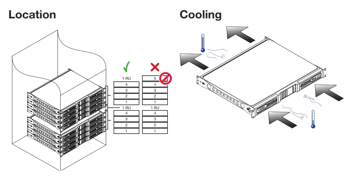
Front Panel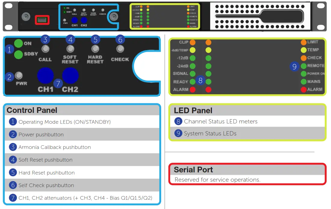
Rear Panel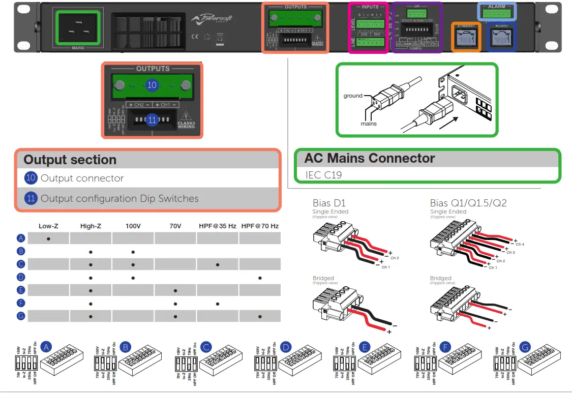
LED Charts
LED Bars, signal metering
| , | – Color | Signal Metering | Lighting | Warnings Description |
| ORANGE | * Clipping DSP+D User Limiter | — | — | |
| YELLOW | -6dB | SOLID ON FLASHING | Thermal warning Thermal protection engaged Auto Standby | |
| GREEN GREEN | -12dB -24dB | — – | — 2 — | |
| GREEN | -60dB | SOLID ON BLINKING | Signal presence Channel muted | |
| GREEN RED | – — | SOLID •N SOLID ON | Channel ready Channel fault’ |
1 Red LED lights on in case of any kind of channel fault that prevents the normal channel operating.
| Lighting | Timings | Description |
| FLASHING | 100 ms ON 900 ms OFF | |
| BLINKING | 500 ms ON 500 ms OFF |
LED Bar, system status
| Color | Name | Lightning | Warnings Description |
| LIMIT | FLASHING SOLID ON | Breaker Save Enabled Breaker Save limiting power draw | |
| TEMP CHECK | SOLID ON SOLID ON BLINKING FAST BLINKING | Thermal warning Thermal protection engaged System self checking Self check completed Self Check Unavailable | |
| REMOTE | SOLID ON OFF | Connected to Armonia Pro Audio Not connected to Armonia Pro Audio | |
| ‘OWER ON | SOLID ON OFF | System ready System off | |
| MAINS | SOLID ON OFF FLASHING FAST BLINKING BLINKING | AC mains voltage within the operating range Undervoltage Over/Undervoltage Warning Overvoltage Mains FUSES blown | |
| ALARM | SOLID ON | PSU fault’ OR Critical Faults |
1 Red LED lights on in case of any kind of PSU fault that prevents normal operating.
| Lighting | Timings | Description |
| FLASHING | 100 ms ON 400 ms OFF | |
| FAST BLINKING | 100 ms ON 100 ms OFF | |
| BLINKING | 500 ms ON 500 ms OFF |
Operating mode LEDs
| Color | Name | Operating mode Standby Power On | ||
| GREEN | POWER ON | – | SOLID ON | |
| ORANGE | STANDBY | SOLID ON | – | |
| ORANGE | AUTO STANDBY | BLINKING | – | |
| ORANGE | ERROR CODE | BLINK COUNTER | – | |
Control Panel
| Label | Action | Description | ||
| Label | Type | |||
| 1 | POWER | Pushbutton | keep pressed for 3 seconds | Toggle system ready/standby mode |
| 2 | CALL | Pushbutton | press | Highlight the amplifier in the Armonia workspace |
| 3 | SOFT RESET’ | Pushbutton | keep pressed for 3 seconds | Reset network parameters to factory default |
| 4 | HARD RESET’ | Pushbutton | keep pressed for 3 seconds | Reboot the system |
| 5 | CHECK | Pushbutton | Keep pressed for 3 seconds | Start the self-checking procedure* |
| 6 | CH12 | Potentiometer | turn counter-clockwise | Attenuate the output level of the signal on channel 1 |
| 7 | CH22 | Potentiometer | turn counter-clockwise | Attenuate the output level of the signal on channel 2 |
The push-buttons are disabled when connected to Armonía.
- Keep pressed both the SOFT RESET button and the HARD RESET button for at least 3 seconds to completely reset the amplifier to its factory default configuration (this won’t deleteanypresetstored in theinternalmemory).
- The potentiometer is in series with the remote level control so it can be used to limit theoutput volume regardless to any remote adjustment.* Press again to resume normal operations
Self Check 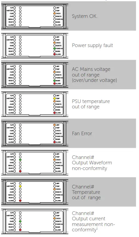
- An 8Ω dummy load is needed to measure the output current. If the dummyload is not applied the system reports a fault.NORTH AMERICA
Void Acoustics North America
Call: +1 503 854 7134
Email: [email protected]
HEAD OFFICE
Void Acoustics Research Ltd,
Unit 15, Dawkins Road Industrial Estate, Poole, Dorset, BH15 4JY
United Kingdom
Call: +44(0) 1202 666006
Email: [email protected]
voidacoustics.com


